International Journal of Emerging Technology and Advanced Engineering
Website: www.ijetae.com (ISSN 2250-2459,ISO 9001:2008 Certified Journal, Volume 3, Issue 2, February 2013)
220
Optimum Siting and Sizing of Shunt Capacitors in Radial
Distribution System using Novel BPSO Algorithm
Nasim Ali Khan
1, S. Ghosh
2, S. P. Ghoshal
31Assistant Professor, EE Department, Aliah University, DD-45, Sector-1, Salt lake, Kolkata-64
2,3Professor, EE Department, National Institute of Technology, Durgapur, 713219
Abstract— Consolidation of shunt capacitors plays an important role in radial distribution networks. Among many of their merits, line loss and total harmonic distortion (THD) reduction, voltage profile improvement and reactive power compensation can be the salient specifications of shunt capacitors. Studies show that non-optimal locations shunt capacitor units lead to increase loss, together with bad effect on voltage profile. Accurate loss minimization is the critical component for efficient electrical distribution power flow. This work presents a Novel Binary Particle Swarm Optimization (NBPSO) technique for improvement of total voltage profile and line loss minimization in power distribution system by incorporating optimal placement of shunt capacitors with constraints which include limits on voltage, sizes of installed capacitors. The technique has been implemented on two different types balanced IEEE distribution.
Keywords— Load flow; Radial distribution system; Shunt Capacitors; Novel Binary Particle Swarm Optimization; Total line loss; Total voltage deviation
I. INTRODUCTION
It has been seen that as much as 13% of total power generated is wasted in the form of losses at the distribution level [1]. The capacities of the radial lines are often limited and hence it is necessary to consider how future load additions will be served. Schmill [2] developed well-known two third rule for the placement of one capacitor assuming a uniform load and a uniform distribution feeder. Baran and Wu [3] distinguished capacitor placement problem separately into a master problem and a slave problem. The master problem was used to determine the location of the capacitors while the slave problem was used to determine the type and size of the capacitors. Duran et al. [4] considered the capacitor sizes as discrete variables and employed dynamic programming to solve the problem. Grainger and Lee [5] developed a nonlinear programming based method in which capacitor location and capacity were expressed as continuous variables. Chen et al. [6] considered the mutual coupling effect of conductors to install capacitors in unbalanced distribution systems. Grainger et al. [7] formulated the capacitor placement and voltage regulator problem and proposed decoupled solution methodology for general distribution system.
Sundharajan and Pahwa [8] proposed the genetic algorithm approach to determine the optimal placement of capacitors based on experiences in the selection of the probability parameters. In [9], a GA-fuzzy logic algorithm has been proposed for solving the discrete optimization problem of fixed shunt capacitor placement and sizing in the presence of voltage and current harmonics. An efficient method for determining the optimal number, location, and sizing of fixed and switched shunt capacitors in radial distribution systems using GA has been presented [10]. Unlike the conventional objective function, a new constraint objective cost function has been formulated to maximize the net annual savings by minimizing real power loss and optimizing the cost of annual investments on shunt capacitors while considering a better voltage profile of the system. Capacitor placement and sizing were performed by using loss sensitivity factors and plant growth simulation algorithm in Rao et al. [11]. The loss sensitivity factor was used to predict which bus has the largest loss reduction when a capacitor was placed. A fuzzy decision function with the assistance of bacterial foraging algorithm creates a
powerful optimization tool, in which both loss
minimization and node voltage improvement in capacitor allocation problem are considered [12]. The objective function is formulated to reduce the cost of peak power and energy loss. Implementing the capacitor allocation problem with this new integer-code algorithm in addition to a fuzzy decision led to better results than previous attempts that focused on reducing peak power in a power system or decreasing network energy loss. S. G. Saranya et al. [13] employed fuzzy expert system (FES) method for
determining suitable candidate nodes in distribution
International Journal of Emerging Technology and Advanced Engineering
Website: www.ijetae.com (ISSN 2250-2459,ISO 9001:2008 Certified Journal, Volume 3, Issue 2, February 2013)
221
IHS employs a method for generating new solution vectors that enhances the accuracy and convergence of the HS algorithm [17] Afaghzadeh et al. [18] also applied the Binary Particle Swarm Optimization (BPSO) for solving optimal capacitor placement problem in a radial distribution network. Here, harmonic distortion of voltage sources was considered in the problem formulation. Harmonic distortion of voltage sources in the network can cause double harmonic current injection, which increases network losses and the number of incidences of resonance. The selected BPSO method considered the discrete nature of the placement problem, whereas most articles have considered this problem to be continuous.
Farzaneh etal. [19] developed a bit string which starts its trip from a random point in the search space and tries to become nearer to the search space and tries to become nearer to the global best position and previous best position of itself. This binary PSO has all major characteristic of PSO. Only the neighborhood in this method contains all particles, inertia weight is zero and the velocity limit has not been applied. In the presented paper, the authors have proposed a new form of Novel Binary Particle Swarm Optimization (NBPSO) technique for improving global search ability to find optimal locations shunt capacitors with an objective of minimizing line losses and total voltage deviation while satisfying the capacity of capacitor for a radial distribution network.
II. POWER FLOW SOLUTION
The load flow solution is carried by the following set of recursive equations (1) and (2) derived from the single line diagram as shown in Fig. 1 .
2 2 2 1 , 1 1
.
i i i i i Li i iV
Q
P
R
P
P
P
(1)2 2 2 1 , 1 1 . i i i i i Li i i V Q P X Q Q
Q (2)
[image:2.612.56.276.504.703.2]
Fig. 1. Single line diagram of a Radial distribution system.
Where Pi is the real power flow into the sending end of
branch i1connecting bus
i
and bus i1; PLi1 is real component of load at bus i1; Ri,i1 is the resistance of line section between busesi
and i1 andi
V is the bus voltage magnitude at bus
i
. Qi is the reactive power flow into the sending end of branch i1connecting busi
and bus i1;Q
Li1 is reactive component of load at busi
1
;1 ,i i
X is the reactance of line section between buses
i
and1
i .
The problem of capacitor allotment with their proper capacities is of great importance. The installation of shunt capacitors at non-optimal places can result in an increase in system losses, voltage deviations and costs. Therefore, a power system planning engineer requires an efficient and fast optimization method capable of indicating the best solution for a given distribution network. The selection of the best places for installation and the preferable sizes of the shunt capacitor banks in large distribution systems is a complex discrete optimization problem.
In order to incorporate the proposed method recursive equations (1) and (2) are modified as follows:
a)Real Power Flow with installation of Shunt Capacitors
P
AP
V
Q
P
R
P
P
P
i i i i i i Li ii
2 1
2 2
1 , 1
1
.
(3)Where
AP
i1is real power magnitude injected at busi
1
;
Pis real power multiplier, set to zero when there is no real power source or set to 1 when there is shunt capacitor power source;b)Reactive Power Flow with shunt capacitors placement
Q
RP
V
Q
P
X
Q
Q
Q
i i i i i i Li ii
2 1
2 2
1 , 1
1
.
(4)Where RPi1is reactive capacitor power magnitude injected at bus i1;
Q
is reactive capacitor power multiplier, set to zero when there is no capacitor power source or set to 1 when there is a capacitor power source;c)Computation of Bus Voltages
)
.
.
(
2
, 1 , 1 22
1 i ii i ii i
i
V
R
P
X
Q
V
(
R
i,i12
X
i,i12)
*
2 2 2 i i iV
Q
International Journal of Emerging Technology and Advanced Engineering
Website: www.ijetae.com (ISSN 2250-2459,ISO 9001:2008 Certified Journal, Volume 3, Issue 2, February 2013)
222
III. PROBLEM FORMULATION
The following sections describe the details of the proposed problem formulation.
A. The Objective Functions
The main advantages of Shunt capacitors in the distribution system are loss minimization in the feeders and the improvement in the voltage profile, i.e. maintaining the voltages at customer terminals with reactive power compensation.
The following functions are computed using the proposed algorithm: Total Line Loss (TLL), Total Voltage Deviation (TVD).
Recommended font sizes are shown in Table 1.
B. Total Line Loss (TLL)
The installation capacitor banks should not result in an increase in the system losses. The power loss of the line section connecting buses
i
andi
1
is computed as:2 2 2
1
,
*
)
1
,
(
i i i i i loss
V
Q
P
R
i
i
P
(6)
, 1
1
P ii TLLn
i
loss (7)
C. Total Voltage Deviation (TVD)
Voltage deviation can also be minimized with integration of Shunt capacitors. The total voltage deviation (TVD) in the system, which is to be minimized, is expressed as:
1
1 1
n i
i
V
TVD (8)
Where
i
=1, 2, 3……..n and Vi is the voltage of ith bus in per unit for the system buses; the ideal magnitude of each bus voltage is unity.D. Constraints
The following constraints are considered [20].
i) Total Power Conservation:
The algebraic summation of all incoming and outgoing powers over the feeders, taking into consideration the feeders‘ losses and the powers supplied by Shunt capacitors should be equal to the total demand at that bus.
ii) Distribution Feeder’s Thermal Capacity:
Power flows in feeders must be within their capacities.
iii) Distribution Substation’s Capacity:
The summation of total powers delivered to the network by the substation‘s transformers must be within the substation‘s capacity limit.
iv) Shunt capacitor Operation Limits:
The Shunt capacitor‘s generated power must be within the Shunt capacitor‘s capacity.
v) Voltage Drop Limits:
The voltage levels at different buses must be within predetermined values.
IV. NOVEL BINARY PARTICLE SWARM OPTIMIZATION
ALGORITHM
The novel particle swarm optimization (NPSO) technique is an advanced version of PSO which improves the global search ability. Variation in the velocity expression (10) of PSO is made by splitting the cognitive component into two different parts. The first part can be called good experience component, that is, the particle has a memory about its previously visited best position. This component is exactly the same as the cognitive component of the basic PSO. The second part is given the name bad experience component. The bad experience component helps the particle to remember its previously visited worst position. The inclusion of the worst experience component in the behavior of the particle gives additional exploration capacity to the swarm. By using the bad experience component, the bird (or particle) can bypass its worst position and always try to occupy a better position. Hence, this optimization technique named as Novel Particle Optimization (NPSO).
Finally, with all modifications, the modified velocity is expressed as follows:
kid k
i k
id k
id k d k
id k id k
i cr pb x cr gb x cr x pworst crv
v 11 22 11 13
1
(9)
Where
v
ik is the velocity ofi
th particle atk
th iteration; 1
k i
v
is the velocity of thei
th particle at
k
1
th iteration;1
r
,r
2andr
3 are the random values in the range [0,1];k id
x
is the current position ofi
th particle in d-dimensionalvector at
k
th iteration;pb
idk andpworst
ik are theInternational Journal of Emerging Technology and Advanced Engineering
Website: www.ijetae.com (ISSN 2250-2459,ISO 9001:2008 Certified Journal, Volume 3, Issue 2, February 2013)
223
The searching point in the solution space is as usual modified by the equation (9).
The Proposed Novel Binary Particle Swarm Optimization
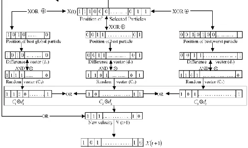
[image:4.612.48.301.234.385.2]The proposed algorithm (NBPSO) is just the complete binary equivalent of NPSO. ‗–‘ sign is represented by XOR (
) operation. ‗+‘ sign represents OR (+) operation, as shown in (17). The implementation steps of NBPSO are shown in Fig. 2 .Fig. 2 . New individual generation in proposed Novel Binary PSO.
The binary equivalents of (9) and (8) are expressed by (14) and (15), respectively. Equation (14) is formed by the following equations (10) to (13)
t p X
td1,n best,n n
(10)
t
g
X
t
d
2,n
best,n
n(11)
t p X
td3,n worst,n n
(12)
m C rand
m C rand
m randC1 1, , 2 1, , 3 1,
(13)
t 1 [C1 d1,
t] [C2 d2,
t] [C3 d2,
t]Vn n n n
(14)
t1 X
t V
t1Xn n n (15)
Where
t
is the iteration cycle. The global best position, the previous best position and the previous worst position of particle are represented by three binary vectors each of M bits. A bit may be 1 or 0. The difference operations in real domain as given in (12) are equivalent to ―XOR‖ operations
in binary domain as given by (13), (14) and(15), respectively. Real random multipliers
C
1.
r
1, C2.r2 and3 1
.
r
C
are replaced by corresponding binary equivalents, asgiven in (13).
Then, updated binary velocity vector is given by (15) as similar to real domain. Finally, binary updated position vector is computed in (15), similar in real domain.
V. RESULTS AND DISCUSSIONS
The proposed NBPSO algorithm has been implemented on two distribution systems consisting of some standard and IEEE distribution systems. The two such distribution systems are IEEE 10-bus [21] and IEEE 69-bus [22].
A) Test System-I
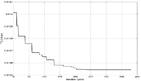
IEEE 10 Bus [21] is a single line main feeder (Base Voltage=23 KV, Base MVA=100 MVA) without laterals and sublaterals having total active and reactive powers of 12.368 MW and 8.372 MVAR, respectively. Without any injection Shunt capacitors‘ reactive powers, the normal load flow yields Total Line Loss (TLL) and total voltage deviation (TVD) as 783.71 kW and 0.69891 p.u., respectively. With no constraints on the total capacities of Shunt capacitors, convergence characteristics of loss minimization and TVD minimization are depicted in Fig. 3 and Fig. 4, respectively. TLL is reduced from 783.71 kW to 38.92 kW and TVD is minimized from 0.69891 p.u. to 0.09214 p.u. by optimal placement and Shunt capacitors, as indicated in Table 1. From Table 1, it is observed two Shunt capacitors, each of 400 kVAR capacity, equivalent to total 800 kVAR, are optimally placed for TLL minimization from 783.71 kW to 20.06 kW and TVD minimization from 0.69891 p.u to 0.38454 p.u. TLL and TVD resulted in case of no capacity limits are obviously less than those in case of fixing capacity limits, though both TLL and TVD are reduced by optimally placing DG sets and Shunt capacitors as compared to the case of absence of these devices.
International Journal of Emerging Technology and Advanced Engineering
Website: www.ijetae.com (ISSN 2250-2459,ISO 9001:2008 Certified Journal, Volume 3, Issue 2, February 2013)
224 Fig. 4. Convergence characteristic of TVD minimization.
TABLE 1
OPTIMUM LOCATIONS AND SIZING OF SHUNT CAPACITORS FOR IEEE 10-BUS SYSTEM
B) Test System-II
Test system-II is IEEE 69 Bus [22] radial feeder (Base Voltage=11KV, Base MVA=10 MVA) with laterals and sublaterals having total active and reactive powers of 3802.19 kW and 2694.6 kVAR, respectively .Without any integration Shunt capacitors, TLL and TVD are obtained as 147.211 kW and 1.03465 p.u., respectively, in normal power flow solution. Convergence characteristics of TLL minimization and TVD minimization are depicted in Fig. 5 and Fig. 6, respectively. From Table 2, it is observed that five Shunt capacitors, each of 100 kVAR capacity, equivalent to total 500 kVAR are optimally placed for TLL minimization from 147.21 kW to 135.57 kW and TVD reduction from 1.03465 p.u to 0.58596 p.u.
Fig. 5. Convergence characteristic of loss minimization.
Fig. 6. Convergence characteristic of TVD minimization.
TABLE 2
OPTIMUM LOCATIONS AND SIZING OF SHUNT CAPACITORS FOR IEEE 69-BUS SYSTEM
Total no. of Shunt Capacitors, each of 100 kVAR
locations Required total
Kvar
TLL/TVD
(Fig. 5 .) 5 7,11,19,22 & 27 500 135.57/.6305
(Fig. 6 .) 5 12,18,20,22 & 27
500 137.62/.585
VI. CONCLUSION
In this paper, the authors have presented a Novel Binary Particle Swarm Optimization (NBPSO) approach to solve the problem of optimal allocation Shunt capacitors. The binary numbers (0, 1) are used for representing the parameters (i.e existence and non-existence of Shunt capacitors) in each string of a population of strings. The inclusion of the worst experience component
worst
p along
with the best experience component
best
p gives additional
exploration capacity to the swarm in NBPSO. By using bad experience component, the particle can bypass its worst position and always try to occupy a better position. NBPSO acts as near global optimizer for determining the optimal sizing and siting of capacitors. Incorporating shunt capacitors in the distribution system can reduce the total line power losses and reduce the total voltage deviation. In conclusion, the authors‘ contribution in this work is successful application of a novel binary PSO algorithm for simultaneous solution of optimal number and placements Shunt capacitors in a wide range of balanced distribution systems.
REFERENCES
[1 ] Song YH, Wang GS, Johns AT, Wang PY. Distribution Network Reconfiguration for Loss Reduction using Fuzzy Controlled Evolutionary Programming. IEE Proc. Gener. Transm.Distrib 1997; 144(4): 345-350
[2 ] Schmill JV. Optimum Size and Location of Shunt Capacitors on Distribution Feeders. IEEE Trans. on Power Apparatus and Systems 1965; 84: 825-832
Total no. of Shunt Capacitors, each
of 400 kVAR
Location( s)
Required total kVAR
TLL in p.u./ kW
TVD in p.u.
(Fig. 3 .) 2 9-10 800 0.0020063/
20.06
0.44221
(Fig. 4 .) 2 9-10 800 0.0042112/
42.11
[image:5.612.52.285.121.258.2] [image:5.612.53.285.561.695.2]International Journal of Emerging Technology and Advanced Engineering
Website: www.ijetae.com (ISSN 2250-2459,ISO 9001:2008 Certified Journal, Volume 3, Issue 2, February 2013)
225 [3 ] Baran M, Wu F. Optimal capacitor placement on radial distribution
system. IEEE Trans. on Power Delivery 1989; 4(1):725–34. [4 ] Duran H. Optimum Number Size of Shunt Capacitors in Radial
Distribution Feeders: A Dynamic Programming Approach. IEEE Trans. Power Apparatus and Systems 1968; 87: 17643- 1774 [5 ] JJ Grainger, SH Lee. Optimum Size and Location of Shunt
Capacitors for Reduction of Losses on Distribution Feeders. IEEE Trans. on Power Apparatus and Systems, vol. 100; no. 3, pp. 1105-1118; March 1981.
[6 ] CS Chen, CT Hsu, Y Yan. Optimal distribution feeder capacitor placement considering mutual coupling effect of conductors. IEEE Trans. on Power Delivery 1995; 10(2):987–94.
[7 ] JJ Grainger, S Civanlar. Volt/var control on Distribution systems with lateral branches using shunt capacitors as Voltage regulators-Part I, II and III. IEEE Trans. on Power Apparatus and systems; vol. 104; no.11; pp. 3278-3297; Nov. 1985.
[8 ] S Sundhararajan, A Pahwa. Optimal selection of capacitors for radial distribution systems using a genetic algorithm. Power Systems, IEEE Transactions on, vol.9; no.3; pp.1499-1507; Aug 1994. [9 ] M Ladjavardi, MAS Masoum. Genetically Optimized Fuzzy
Placement and Sizing of Capacitor Banks in Distorted Distribution Networks. IEEE Transactions on Power Delivery; vol. 23; no. 1: 449-456.2008.
[10 ]RS Rao, SVL Narasimham, M Ramalingaraju. Optimal capacitor placement in a radial distribution system using Plant Growth Simulation Algorithm. Electrical Power and Energy Systems 33:1133–1139;2011
[11 ]A Swarnkar, N Gupta, KR Niazi. Optimal Placement of Fixed and Switched Shunt Capacitors for Large- Scale Distribution Systems using Genetic Algorithms. Innovative Smart Grid Technologies Conference;1- 8;2010;
[12 ]H Mohkami, R Hooshmand, A Khodabakhshian. Fuzzy optimal placement of capacitors in the presence of nonlinear loads in unbalanced distribution networks using BF-PSO algorithm, Applied Soft Computing 11:3634–3642; 2011
[13 ]SG Saranya, E Muthukumaran, SM Kannan, S Kalyani. Optimal Capacitor Placement in Radial Distribution Feeders Using Fuzzy-Differential Evolution‖ ,Proceedings of the National Conference on Innovations in Emerging Technology:85-90.2011.
[14 ]R Sirjani, A Mohamed, H Shareef. Optimal Capacitor Placement in a Radial Distribution System Using Harmony Search Algorithm. Journal of Applied Sciences,vol.10; no.23:2996-3006; 2010 . [15 ]R Sirjani, A Mohamed, H Shareef. Optimal Capacitor Placement In
A Distribution Network With Nonlinear Loads Using Harmony Search Algorithm. Australian Journal of Basic and Applied Sciences; 5(6); 461-474; 2011.
[16 ]R Sirjani, A Mohamed, H Shareef. An Improved Harmony Search Algorithm for Optimal Capacitor Placement in Radial Distribution Systems. The 5th International Power Engineering and Optimization Conference; 323-328; 2011.
[17 ]R Sirjani, A Mohamed, H Shareef. Optimal Capacitor Placement in Three-Phase Distribution Systems Using Improved Harmony Search Algorithm. International Review of Electrical Engineering (I.R.E.E.), (accepted for publication in August 2011).
[18 ]H Afaghzadeh, KH Valipoor, M Ebtehaj, H Ghadimi. Optimal capacitor placement with consideration of voltage source harmonic distortion effect on radial distribution networks using binary particle swarm optimization. 16th Conference on Electrical Power Distribution Networks; 1-6. 2011.
[19 ]F Afshinmanesh, A Marandi, A Rahimi-Kian. A Novel Binary Particle Swarm Optimization Method Using Artificial Immune System. The International Conference on ; vol.1; no., pp.217-220; 21-24 Nov. 2005.
[20 ]W El-Khattam, YG Hegazy, MMA Salama. An Integrated Distributed Generation Optimization Model For Distribution System Planning. IEEE Transactions on Power Systems; vol. 20; no. 2; May 2005.
[21 ]JJ Grainger, SH Lee. Capacity Release by Shunt Capacitor Placement on Distribution Feeders: A New Voltage-Dependent Model. Power Engineering Review; IEEE , vol.per-2, no.5, pp.42-43; May 1982.