Model Reference Adaptive System based Speed
Sensorless Control of Induction Motor using Fuzzy-PI
Controller
U. Saranya
PG Scholar
Department of Power Electronics and Drives Sri Ramakrishna Engineering College
Coimbatore, India
S. Allirani,
Ph.D. Associate ProfessorDepartment of Electrical and Electronics Engineering
Sri Ramakrishna Engineering College Coimbatore, India
ABSTRACT
In this paper a Model Reference Adaptive System (MRAS) is presented as the speed estimation technique in which the error speed is estimated by comparing reference model and adaptive model and further the error speed is used to obtain the rotor speed. Proportional Integral (PI) is designed for controlling purpose. A non-linear fuzzy-PI controller is used to optimize the speed error value. The Proposed MRAS based speed sensorless control of Induction Motor (IM) drive will ensure the better dynamic performance and reliability, compared to conventional methods. The proposed scheme is simulated using MATLAB/Simulink software.
Keywords
Sensorless speed control, Model Reference Adaptive System (MRAS), Induction Motor, stationary reference frame, speed estimation.
1.
INTRODUCTION
IMs are widely used as variable speed drives in industries due to their advantages like rugged construction, low cost, low maintenance and better performance. In order to get good performance of sensorless vector control different speed estimation methods have been proposed such as Extended kalman filter [1], sliding mode control [2], MRAS [3], [5] and [6], direct calculation method. Among these techniques, MRAS schemes are the most common strategies employed due to their relative simplicity and low computational effort. MRAS –based speed estimators developed so far can be grouped into the following three groups
1. The back Electromotive Force (back EMF)-error-based MRAS scheme, which is proposed by Rashed and A.F.Stronach in which the error vector used for the rotor speed correction is obtained from the comparison of the measured and calculated back EMF of the IM [7].
2. The rotor-flux error based MRAS scheme developed by Schauder [8] and Tamai [10] et al, is one of the most popular methods.The speed is estimated through the closed loop signal from the output of the Proportional Integral (PI) controller operated by the flux –error signal.
3. The stator-current-error-based MRAS schemes, where the stator current is estimated by suitable
stator-current model and compared with measured value to obtain the speed-error correction signal [11]. In this paper a Model Reference Adaptive System (MRAS) is used as the speed estimation technique, in which the error speed is estimated by comparing reference model and adaptive model and the error is used to obtain the rotor speed. They have a simple structure and can offer a satisfactory performance over a wide range of operation. Fuzzy logic controller (FLC) is another nonlinear optimizer to minimize the speed tuning signal for rotor speed estimation [13]. The chapter 2 describes about rotor flux MRAS based speed observer, chapter 3 gives the control strategy (fuzzy logic controller) used in the system, chapter 4 presents the simulation of the MRAS based control of IM with detailed analysis of various parameters and chapter 5 concludes the applications of MRAS based controller in various fields with improved performance.
2.
ROTOR FLUX MRAS BASED SPEED
OBSERVER
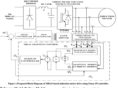
The block diagram of MRAS based speed estimation and sensor less speed control of IM is shown in figure1.The three phase input supply is given to the rectifier which converts AC to DC and is given to the DC link inductor to smoothen the DC voltage. The DC output voltage fed to the three phase voltage source inverter which converts DC to AC and then given to the IM drive.
The voltage and current signals are sensed from the output of the inverter and is given for three phase to two phase transformation which consist of two transformation such as Clarke transformation (abc to αβ) and park transformation (αβ to dq).The Vdq and Idq signals are given to the MRAS controller
which optimizes the error speed by using fuzzy-PI controller to get the estimated rotor speed. The estimated speed is compared with reference speed and accordingly the PWM generator which generates the pulses which is given to the gate drivers. When the firing input is given to the voltage source inverter based on turning on and off inverter switches, the induction motor speed is controlled. The speed 𝜔𝑟 isestimated by the
Figure 1.Proposed Block Diagram of MRAS based induction motor drive using Fuzzy-PI controller.
2.1.
Reference Model (Voltage Model)
Consider the voltage model stator equation which is defined as a reference model. It generates the reference value of the rotor flux components in the stationary reference frame (ds -qs).The ds-qs equivalent circuits are shown in figures 2(a) &2(b) respectively.
Figure 2(a). ds -equivalent circuit
Figure 2(b).qs-equivalent circuit
The reference model equations for the rotor flux in stationary reference frame are obtained from the equivalent circuits and shown in equations (1) & (2).
d dt φdrs =
Lr
Lm Vds s − R
s+σsLs ids s (1) d
dt φqrs = Lr
Lm Vqs
s − R
s+σsLs iqs s (2)
2.2.
Adaptive Model (Current Model)
The current model flux equations are defined as an adaptive model. This model calculates the flux from the input stator current only if the speed signal 𝜔𝑟is known. The rotor flux components are obtained with the help of speed and current signals. The ds-qs equivalent circuits are shown in figures3 (a) &3(b).
Figure 3(a). ds- equivalent circuit
Figure 3(b).qs- equivalent circuit
Rs Lls Llr
Rr
idss idr
s
ψdss ψ
drs
Vdss ωrψqr
s
+
-Lm
Rs Lls Llr R
r
iqss iqr
s
ψqss ψ
qrs
Vqss ωrψdr
s
+
-Lm
Rs Lls Llr Rr
iqss iqr
s
ψqss ψ
qrs
Vqss ωrψdr
s
+
[image:2.595.51.296.471.692.2] [image:2.595.312.557.514.736.2]The adaptive model equations are obtained from the equivalent circuits and shown in equations (3) & (4)
dφdrs
dt = Lm
Tr ids
s −ω
rφqrs − φdrs
Tr (3)
dφqrs
dt = Lm
Tr iqs
s +ω
rφdrs − φqrs
Tr (4) With the correct speed signal, ideally the fluxes are calculated from the reference model and those calculated from the adaptive model will match that isφrd =φrq and φrq =φrd where the φrd and φrqare the adaptive model outputs.
The rotor flux MRAS scheme, this is performed by defining a speed tuning signal εω to be minimized by PI-Fuzzy controller which is generates the estimated speed that is fed back to the adaptive model.
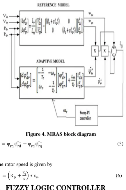
[image:3.595.62.279.307.633.2]The error speed is the difference between the product of rotor flux of reference and adaptive model [9] of corresponding dq axis. The expressions for the speed tuning signal and the estimated speed is given by equation (5) & (6) respectively.
Figure 4. MRAS block diagram
εω=φrqφ −rd φrdφrq (5)
The rotor speed is given by
ωr= Kp+Ksi ∗εω (6)
3.
FUZZY LOGIC CONTROLLER
Fuzzy Logic Controller (FLC) has become popular in several industrial control applications are solving control, estimation and optimization problem, ease of understanding and implementations, ability to handle uncertainty and imprecision [13].In this section, FLC is used for error minimization in the conventional MRAS speed observer. The proposed FLC is a Mamdani-type rule base where the inputs are the speed tuning signal εω and its change in error
speed dεω/dt, which can be defined as,
(a)
(b)
(c)
Figure5. Fuzzy controller input and output functions (a) error (b) change in error (c) change in estimated speed.
Each variable of the FLC has seven membership functions. The following fuzzy sets are used: NB=negative big, NM=Negative Small, ZE= Zero, PS=Positive Small, PM=Positive Medium and PB= Positive Big. The universe of discourse of the inputs and outputs of the FLC are chosen between -0.1 to 0.1with triangular membership functions as shown in Figure.5. Table I shows the fuzzy rule base with 49 rules [14]. FLC is modeled using the MATLAB fuzzy-logic toolbox GUI.
Table I-Linguistic Rule Base
Ԑω
dԐω/dt
NB NM NS ZE PS PM PB
NB NB NM NM NS NS NS ZE
NM NM NM NS NS NS ZE PS
NS NM NM NS NS ZE PS PM
ZE NB NM NS ZE PS PM PM
PS NS NS ZE PS PS PM PM
PM NS ZE PS PS PS PM PM
[image:3.595.308.550.541.763.2]4.
SIMULATION RESULTS
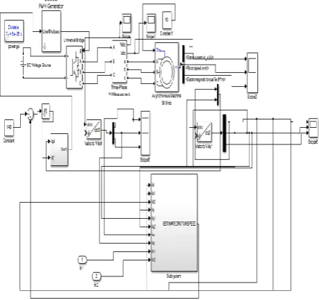
[image:4.595.56.286.165.381.2]Here, a squirrel cage type IM of three phases, 2 poles, 565 V is used in simulation. The figure6show the overall Simulink model of IM drive system. It consists of inverter, induction motor, 3 phase to 2 phase transformation and model of subsystem which consists of MRAS and Fuzzy-PI controller.
Figure 6. Overall Simulink model of sensorless control of induction motor using MRAS with fuzzy-PI controller
The sensorless control of induction motor using MRAS is simulated on MATLAB/SIMULINK-platform to study the various aspects of the controller. Figure 7 shows the simulink block of MRAS with Fuzzy-PI controller.
Figure7. Simulink block diagram of MRAS with fuzzy-PI Controller
The MRAS consist of two blocks, the reference model and adaptive model. By using suitable adaptive mechanism the speed ωr can be estimated and taken as feedback. Fuzzy-PI
controller is used to optimize the error speed.
Figure8(a). Direct rotor flux of reference model
Figure 8(a) indicates that both the direct and quadrature rotor fluxes of reference model with 90 phase shift.
Figure 8(b). Quadrature rotor flux of reference model
Figure 8(b) indicates that both the direct and quadrature rotor fluxes of adaptive model with 90 phase shift.
Figure8(c). Direct rotor flux of adaptive model
0.1 0.2 0.3 0.4 0.5 0.6
-2 -1.5 -1 -0.5 0 0.5 1 1.5 2
Time in secs
Fl
u
x
i
n
w
b
0 0.1 0.2 0.3 0.4 0.5 0.6
-1.5 -1 -0.5 0 0.5 1 1.5 2
Time in secs
Fl
u
x
i
n
w
b
4.85 4.9 4.95 5
-0.3 -0.25 -0.2 -0.15 -0.1 -0.05 0 0.05 0.1
Time in secs
Fl
u
x
i
n
w
[image:4.595.330.531.312.474.2] [image:4.595.328.520.539.717.2]Figure8(d). Quadrature rotor flux of adaptive model
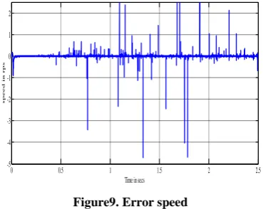
The reference model is compared with the adaptive model and the error speed is obtained and shown in figure 9.
Figure9. Error speed
The simulation results of stator current, rotor speed and electromagnetic torque are shown in figure 10.
Figure10. Stator current, rotor speed and electromagnetic torque
5.
CONCLUSION
In this paper, a MRAS based speed estimator is proposed for estimating the rotor flux and speed of an IM. The proposed method has better performance under both steady and transient state conditions. The simulation results of speed sensorless control of IM using MRAS technique using Fuzzy-PI controller were carried out by using Matlab/Simulink and simulation results are presented and analyzed. This MRAS based estimator can be used for high performance IM especially at very low speeds. In this paper MRAS based speed sensorless control of induction motor is proposed which can be widely used for textile mills and electrical vehicle applications.
[image:5.595.75.260.284.431.2]Appendix
Table II-Motor Parameters
Power 10Hp
DC Voltage 565V
Stator Resistance(Rs) 0.7384Ω
Stator Inductance(Lls) 0.003045H
Rotor Resistance (Rr) 0.7042 Ω
Rotor Inductance (Llr) 0.003045H
Mutual Inductance(Lm) 0.1241H
Inertia 0.0343 J(kg.m2)
Pole 2
Friction factor 000503F(N.m.s)
6.
REFERENCES
[1] Bose. B. K, Modern Power Electronics and AC Drives. New Delhi, India: Prentice-Hall, 2006, ch. 8, pp. 333– 435.
[2] Comanescu M. andXu L., “Sliding mode MRAS speed estimators for sensorless vector control of induction machine,” IEEE Trans. Ind. Electron.,vol. 53, no. 1, pp. 146–153, Feb. 2006.
[3] Kwon Y. A and Jin D.W., “A novel MRAS based speed sensorless control of induction motor,” in Proc. 25th Annu. Conf. IEEE Ind. Electron. Soc.,1999, pp. 933– 938.
[4] Mir S., Elbuluk M.E., and Zinger D.S., “PI and fuzzy estimators for tuning the stator resistance in direct torque control of induction machines,” IEEE Trans.
0.12 0.14 0.16 0.18 0.2 0.22 0.24 0
1 2 3 4
Time in secs
Fl u x i n w b
0 0.5 1 1.5 2 2.5
-5 -4 -3 -2 -1 0 1 2
Time in secs
s p e e d i n r p s
0 0.5 1 1.5 2 2.5 3 3.5 4 4.5 5
-200 -100 0 100 200
Time in secs
C u r r e n t i n a m p s
Stator current (amps)
0 0.5 1 1.5 2 2.5 3 3.5 4 4.5 5
-100 0 100 200
Time in secs
S p e e d i n r p s
Rotor speed (wm)
0 0.5 1 1.5 2 2.5 3 3.5 4 4.5 5
-200 0 200 400
Time in secs
T o r q u e i n N -m
[5] Maiti S., Chakraborty C., Hori Y., and Ta M.C., “Model reference adaptive controller-based rotor resistance and speed estimation techniques for vector controlled induction motor drive utilizing reactive power,” IEEE Trans. Ind. Electron., vol. 55, no. 2, pp. 594–601, Feb. 2008.
[6] Pydiraju G., Daivaasirvadam M. “Sensorless Speed Control of Induction Motor Using MRAS”, International Journal of Recent Technology and Engineering (IJRTE) ISSN: 2277-3878, Volume-1, Issue-5, Nov. 2012. [7] Rashed M. and Stronach A.F., “A stable back-EMF
MRAS-based sensorless low speed induction motor drive insensitive to stator resistance variation,” Inst. Electr. Eng. Proc. Electr. Power Appl., vol. 151, no. 6,pp. 685– 693, Nov. 2004.
[8] Schauder C., “Adaptive speed identification for vector control of induction motors without rotational transducers,” IEEE Trans. Ind. Appl., vol. 28, no. 5, pp. 1054–1061, Sep./Oct. 1992.
[9] Suman Maiti, VimleshVerma, Chandan Chakraborty and Yoichi Hori “An Adaptive Speed Sensorless Induction Motor Drive With Artificial Neural Network for Stability Enhancement”, IEEE Trans. Ind. Informatics., Vol. 8, No. 4, November 2012.
[10] Tamai S., Sugimoto H., and Masao Y., “Speed sensorless vector control of IM with model reference adaptive system,” in conf. Rec. IEEE/IAS Annu. Meeting, 1987, pp. 189-195
[11] Teresa orlowska-kowalska, Senior Member, IEEE, and Mateusz Dybkowski “ Stator-Current-Based MRAS Estimator for a Wide Range Speed-Sensorless IM drive”, IEEE Transactions on industrial electronics, vol. 57, no. 4, April 2010.
[12] Vasic V. and Vukosavic S., “Robust MRAS-based algorithm for resistance and rotor speed identification,” IEEE Power Eng. Rev., vol. 21,no. 11, pp. 39–41, Nov. 2001.
[13] Allirani S., Jaganathan V., “Torque ripples minimization in DTC band Induction motor drive using fuzzy logic technique” International Journal of Computer Applications (IJCA), vol.40, No.1,pp.25-31,Feb.2012. [14] Gadoue S.M., Giaouris D. and Finch J.W. “MRAS
senorless vector control of an induction motor using new sliding-mode and fuzzy-logic adaptation mechanisms” IEEE Trans. on Energy Conversion, vol. 25,no. 2, pp. 394-402,2010.
[15] Mustapha MESSAOUDI, Habib KRAIEM, Mouna BEN HAMED, Lassaad SBITA and Mohamed Naceur ABDELKRIM., “A Robust Sensorless Direct Torque Control of Induction Motor based on MRAS and Extended Kalman Filter” Leonard Journal of Sciences, Issue 12, pp.35-36, January-June 2008.