THE MODEL FOR STUDIES OF LOAD FOR THE ROLLER BIT
SUPPORT BEARINGS
Vladimir Alexeyevich Pyalchenkov, Vladimir Veniaminovich Dolgushin and Gennady Andreyevich Kulyabin
Tyumen Industrial University, Volodarskogo Street, Tyumen, Russia E-Mail: [email protected]
ABSTRACT
The overview of scientific research works in which techniques and results of analytical and experimental studying of power and kinematic characteristics of operation of roller drill bits is stated in this paper. The interest to this subject is explained by its great practical importance. Economic indicators of a well construction depend on the overall performance of the drilling tool. At the same time, results of researches often have contradictory character that can be explained by the high complexity of processes happening during the bit operation on a borehole bottom. The analyzed works are grouped according to the fields of researches. The overview of main works devoted to studying of kinematics of roller drill bits, to interaction of elements of drilling bit cutting structure with the destroyed rock, to the calculation of efforts and analysis of tension of drilling bit bearing and cutting structure elements by means of various experimental methods and methods of mathematical modeling is provided. The provided analysis of known results of researches in this field is not comprehensive, but can be useful in case of further studying of this issue. The results of the investigational study of a load distribution between drilling bit bearings applying the model of the drilling bit bearing assembly made of photoelastic material are also considered in this paper. It is established that the nature of a load distribution between bearings depends on the radius of the effort application to a roller. In case of a little change of radius in a certain area, there is a considerable redistribution of loading between drilling bit bearings. The placement recommendations for the optimization of a drilling bit cutting structure on a roller surface are offered according to research results.
Keywords: drilling, bit, roller, support, loading.
1. INTRODUCTION
The large number of researches was engaged in work modeling of a roller drill bit and studying of main regularities of power interaction of the drilling bit cutting structure with a borehole bottom and bearings of basic rollers’ assemblies. Such interest in this subject is explained by its great practical importance. Economic indicators of a well construction in many respects depend on the overall performance of the drilling tool. At the same time results of researches often have contradictory character that can be explained by high complexity of the processes happening during the drilling bit operation on a borehole bottom. This paper is devoted to the mechanism modeling the drilling bit cutting structure and the destroyed rock interaction (Spivak and Popov, 1994). Bit tooth is pressed into the rock by axial force and at the same time makes the compound motion depending on rotation parameters of a roller and a bit, by-passing rollers through the borehole bottom. At the same time, the next tooth moves to a surface of rock and strikes blow to it. In the following moments the loading is redistributed from the first tooth on the second, and further the first tooth comes out of contact with the rock. The investigational studies of interaction of separate elements of the drilling bit cutting structure with the rock are executed according to the scheme of drilling by one tooth. Results of the investigational study of a bit and the rock interaction are given in (Geoffroy, et al. 1997; Rao, et al. 2002).
The axial effort operating on a bit from the destroyed rock is defined in (Elsayed, et al. 2001). The
angular speed of a roller was averaged within one turn in the majority of conducted investigational studies. However it is established that the instantaneous gear ratio of rollers
vary by 1, 4 … 1, 75 times within one turn. At the same time minima of the instantaneous gear fall on vertical teeth positions about the bottom. Analytical dependences to find impact speeds and the motion in contact of drilling bit cutting structure elements of the ring gear with the bottom and also nonlinear dependences between turn angles of the ring gear round its axle and around a bit axis at the operation on a deformable bottom are offered in (Spivak and Popov, 1994; Eygeles, et al. 1993). Using in this
model the wear resistance as the criterion of optimization, the author (Bilanenko, 1994) at the expense of a variation by geometrical parameters determines their optimum ratio. It was accepted in the analysis that the immersion depth of teeth in the rock is considered only for the determination of working parts of teeth. Force of resistance to the motion in the contact with the rock is constant during the contact time though it is known that the rock resistance force to destruction depends on many factors and changes over a wide range, both in size, and in the direction.
The interesting mathematical model of the roller drill bit operation describing interaction in the system "a drilling string - a bit - a bottom" is used in (Eygeles, et al.
definition of the rock reaction operating on tops of teeth at each step of this mathematical model implementation of a bit it is necessary to use the results received experimentally at the test panel in which the interaction of a tooth with the rock, unlike real conditions, is provided due to rigid kinematic link. Various mathematical models of the roller drill bits for the analytical determination of efforts operating on bearings of a roller support are offered in (Langleben, 1995; Postash, 1959; Pyalchenkov, 2014). In (Langleben, 1995; Postash, 1959) it is supposed that the axial loading is distributed evenly between all rollers, and the reaction of a bottom is proportional to the width of teeth. The required efforts are defined from the consideration of balance conditions of a roller and a foot, and also from additional conditions of deformation. At the same time, if in (Langleben, 1995) the pivot shaft and roller deformations are considered, but contact deformations and gaps in bearings are neglected, then in (Postash, 1959), on the contrary, only contact deformations and gaps in bearings are considered. As a result, authors come to opposite conclusions. According to the paper (Langleben, 1995) the retaining drill bit bearing takes up the biggest radial load, but in work (Postash, 1959) the load operating on this bearing is minimal. In (Pyalchenkov, 2014) the roller built up on a pivot shaft on three rolling bearings and loaded with the axial force applied at a certain distance from a bit axis is considered as the model. As the system of forces operating on a roller is statically indefinable, for its solution the additional equations of the system deformation are worked out. At the same time the deformation of a pivot shaft and contact deformations in bearings were considered. The calculation of size of contact tension in bearings by this technique shows that the largest tension arises in the retaining drill bit bearing. It corresponds to conclusions of a number of the studies claiming that the ball bearing operates in the most severe conditions.
2. METHODS
The technique and a complex of devices and gages for the experimental determination of loadings took up by each roller (section) during their operation on a bottom are offered in (Komm, et.al. 1976; Pyalchenkov,
Pyalchenkov and Dolgushin, 2016). The technique consists of the experimental determination of the loading operating on each section of a roller drill bit model during its work on a bottom with the subsequent analytical assessment of these loadings distribution between support bearings. However, some assumptions which reduce the reliability of the determined power impact on a roller were made at the development of this technique. The loadings operating on the bit roller teeth while drilling are determined by direct measurement with tensometric sensors pasted on side surfaces of teeth. The difficulties of efforts’ measurement in this case are that teeth have the small sizes and rollers, with the sensors pasted on them, rotate. The principle of the bottom differentiation is also used for the experimental assessment of load elements of the drilling bit cutting structure (Pyalchenkov, Pyalchenkov, Dolgushin, Danilov and Kurbanov, 2016).
The bottom is executed in the form of three concentric steel rings, based on the measuring device that allows measuring the total axial loadings and torques operating on rings of all bit rollers, but does not give an idea of loadings distribution on the drilling bit cutting structure of each roller. An additional differentiation of a bottom by two sectors, working (measuring) and non-working gives a possibility of separate determination of efforts operating on rings of each roller. Results of researches showed that for 215.9K-PV bits the greatest axial loading is took up by average rings. An essential lack of this method is the necessity of a metal bottom application. The device for measurements and the registration of axial loading twisting and the bending moments operating on a bit while drilling the rock is described in (Trushkin, 2006). Modern means of record and disaggregation of power parameters of a bit operation are used. Measurements in bench conditions were carried out for marble. Data on power consumption of marble destruction jumps of destruction, dynamism of torque, axial and cross forces for the roller bits and winged scraping bits are obtained. It is established that bits generally operate within the third jump of destruction. The final and element model of a bit considering various combinations of teeth with a bottom contact, bottom pliability, the teeth geometry and elements of a support and allowing receiving assessment of real loads of each section is offered in (Morozov, 2014). Teeth of a roller are modeled by a complex of 6 cores of the set rigidity. The availability of various options of teeth with a bottom contact leading to the change of size and the direction of equally effective load of bit sections, bottom pliability under various geometry teeth affect is considered. Results of complex theoretical and investigational studies of load of roller bit elements, provided in (Dolgushin, 2008) are of considerable interest. As a result of theoretical researches the analytical dependences for the determination of forces acting on a roller from the destroyed rock are received. However, the received dependences include coefficients which need to be determined experimentally. The method of disclosure of static indeterminability of a bearing assembly allowing establishing the dependence of efforts’ distribution on elements of a bearing assembly by the magnitude of forces operating on a roller and geometrical parameters of a basic assembly is offered. For investigational studies of the loadings operating on a roller the device described in (Komm, etal. 1976) was used. At the same time, the
equally effective reaction of the bottom to a roller and a well axis (radius of the loading application R). For an illustration of this dependence nature one of the most modern and visual teaching methods of a research of the valid tension of difficult constructions the polarizing and optical method (Froht and Fotoelasticity, 1948) is used. This optically-sensitive method is based on the property of some materials and becomes birefringent in case of deformation under the influence of loading. The flat model of a roller assembly which sizes corresponded to the valid size of basic elements of a III215.9K-PV bit is made from the optically - sensitive material. The scheme of device for fixing and loading of a flat model of a roller assembly is presented in Figure-1. Loading of model 1 is performed by replaceable freights 2 through the lever system 3.
Figure-1. The device scheme for fixing and loading of the flat photoelastic model of a roller assembly: 1- model; 2-shift freights; 3-lever system; 4-body.
The polarized light, passing through the loaded model, decays on coherent waves. They pass the model with the different speed depending on the main tensions
2
and sensitivity of material and on the wavelength of monochromatic light. Various speeds lead to the path difference of two waves connected with the main tensions in the model material by the dependence:
1
2
c
t
R
t ; (1)Where
c =a constant, dependent: on properties of material; t = the model thickness.
Dependence (1) can be presented in the form:
1
2
m
n
; (2) Wherem = fringe order; n = fringe value.
In places where
m
0
,
1
,
2
…dark areas willbe observed on the screen, and where
2
3
;
2
1
m
… themost lighted areas.
3. RESULTS
Figure-2. The fringes’ contour of a roller assembly model at R = 70 mm.
(а)
(b).
In case of radius increase up to R = 95 mm the load on a small ball remains approximately the same, as well as in case of R = 45 mm. In the fringes’ direction of a ball model it is possible to trace how the angle of a ball with a pivot shaft and a roller contact varies when the external loading application radius is changed. When the line of external force action passes approximately through the center of a ball (Figure-2) that the engagement angle of a ball with a roller body will be the smallest, equal about
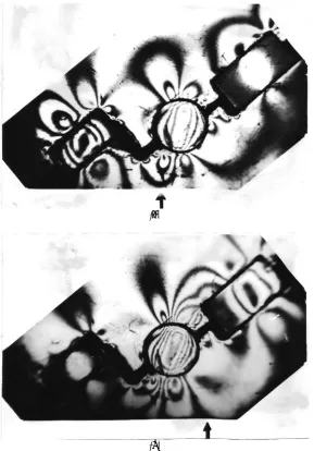
59°. In case of the displacement of a loading application point, both to a bit axis, and to the periphery there is an increase in a contact angle. When the loading application radius R=45 mm the angle of contact becomes equal to 72°. The author considered how the pattern of bearings congestion change in case of displacement of the force action line near R = 71 mm. In Figures 4 and 4 b the fringes contours are shown at R = 66 mm and R =77mm.
(а)
[image:5.612.164.453.195.609.2](b)
Figure-4. Fringe contours of a roller assembly model at R = 65 mm (a) and R = 75 mm (b).
4. DISCUSSIONS
If we compare the photos of fringes’ contours provided on these pictures to photos of fringes’ contours in Fig. 2, it is easy to notice that at minor change of a radius in this area there is a considerable redistribution of loading between rolling elements. So at the reduction of radius from 70 mm to 65 mm the fringe order in the center of a big roller decreases from 1, 3 to 0, 5. At the same time the
roller turn on a pivot shaft does not occur. At the same time there is the greatest contact rigidity of the bearing assembly as the loading is perceived by all three bearings at the same time. At displacement of an external loading application point to the right or to the left for 5 mm and more there is a turn of a roller around the lower ball leading to the redistribution of loading between bearings. Loading is generally perceived only by two bearings and it reduces the contact rigidity. Besides, at increase of the loading application radius of more than 70 mm the displacement of the equally effective reaction of a bottom to an outer edge of a big roller perceived by this roller occurs. It also reduces the contact rigidity in the big roller bearing and reduces the general vertical rigidity of roller assembly at big external loading application radiuses.
5. CONCLUSIONS
The given results of the qualitative analysis of loading distribution between roller support bearings are quite coordinated with the results of analytical (Pyalchenkov 2014) and investigational (Pyalchenkov, Pyalchenkov and Dolgushin, 2016) studies of the roller assembly rigidity. By authors’ researches it is established that the loading distribution between ring gears of a roller depends, including, and on vertical rigidity of “the roller-the bottom” system. The deformation of details of roller-the basic roller assembly has a significant effect on the rigidity of this system. The maximum vertical rigidity of roller assembly at the studied bits takes place at R = 70 mm as in this case the loading is distributed between all three bearings of a support that is confirmed also by the results given above. Therefore, the ring gear of a roller located on this radius will perceive the greatest vertical loading. Therefore when developing the scheme of a bottom defeat for bits of this type it is necessary, whenever it is possible not to have drilling bit cutting structure elements on this radius.
REFERENCES
Bilanenko N. A. 1994. Establishment of optimum kinetic characteristics of the roller drill bits for the purpose of increase in efficiency of well-drilling: dissertation of the candidate of technical sciences. Central Asian Research University of Natural Gas, Tashkent. p. 219.
Dolgushin V. V. 2008. The methodology development of processes modeling of drilling and borehole mechanisms technology: dissertation of the candidate of technical sciences. Tyumen State Oil and Gas University, Tyumen. p. 260.
Elsayed M. A. and Washington L. E. 2001. Drillstring Stability Based on Variable Material Specific Force and Using a Sharp Three-Insert Polycrystalline Diamond Compact (PDC) Coring Bit. J. Of Energy Resources Technology. 123: 138-143.
Eygeles R. M., Levin A. B. and Lubyany D. A. 1993. Modeling of kinematics and dynamics of roller drill bits.
Construction of oil and gas wells on shore and off-shore. 1-2: 41-43.
Froht M. M. 1948. Fotoelasticity. Moscow, Gostekhizdat. p. 432.
Geoffroy H., Nguyen Miah D. and Putot C. 1997. Study on Interaction Between Rocks and Worn PDC’s Cutters. Int. J. of Rock Mechanics and Mining Sciences. 34(314): 611.
Komm E. L., Perlov G. F. and Mokshin A. S. 1976. The investigation of loading of roller bit sections. Works VNIIBT. 36: 27-36.
Langleben M. A. 1955. To calculation of a roller bit support. The Azerbaijani oil economy. 11: 19-22.
Morozov L. V. 2003. The durability increase of drilling bits on the basis of the computer analysis of design and assembly elements: dissertation of the candidate of technical sciences. Samara State Technical University, Samara. p. 180.
Postash S.A. 1959. About the calculation of the three roller bit support. News of higher education institutions. Oil and gas. 8, 91-98.
Pyalchenkov V. A. 2014. Analytical determination of reactions in the roller drill bit support. News of higher education institutions. Oil and gas. 3: 66-72.
Pyalchenkov V.A., Pyalchenkov D.V., Dolgushin V.V. and Kulyabin G.A. 2016. Experimental Method for Measuring the Forces Acting On the Cutters of the Rolling Cutter Bit. Research Journal of Pharmaceutical, Biological and Chemical Sciences. 7(5): 663-669.
Pyalchenkov V.A., Pyalchenkov D.V., Dolgushin V.V., Danilov O.F. and Kurbanov Ya.M. 2016. Method of experimental determination of forces, acting on the bearings of rolling cutter bit. Oil Industry. 8: 112-115.
Rao, K. U. M., Bhatnagar, A. and Misra, B. 2002. Laboratory investigations on rotary diamond drilling. Geotechnical and Geological Engineering. 20: 1-16.
Spivak A. I. and Popov A. N. 1994. The destruction of rocks when drilling a well: the text-book for higher education institutions. Moscow: Nedra. p. 261.