Comparative Analysis of RCC and
Steel-Concrete-Composite (B+G+ 11 Storey) Building
Mr. Nitish A. Mohite1, Mr. P.K.Joshi2, Dr. W. N. Deulkar3 1, 2
Department of Civil Engineering, PVPIT, Budhgaon, Sangli, MS, India
3
Associate Professor, Department of Civil Engineering, DYPCOET, Kolhapur, MS, India
Abstract - Steel-concrete-composite buildings are formed by connecting the steel beams with concrete slab or profiled deck slab with the help of mechanical shear connectors so that slab and beam act as a single unit. In the present work, options of construction of (B+G+11storey) commercial building, situated in Kolhapur, with steel-concrete-composite and RCC are studied and compared with each other. Equivalent linear Static Method of Analysis explained in ETABS version 15 software is used and results are compared for different parameters. Comparative parameter includes roof deflections, base shear, storey drifts, for the building and axial forces and bending moments for column’s and beams at different level. It is observed that steel-concrete-composite building is found to be more safe and economical and better option.
Key Words: Steel-concrete-composite, RCC, Shear connector, ETAB software, Equivalent linear Static Method
I. Introduction
In the past, structural engineers had the choice masonry building. Today multi-story buildings in India are constructed with R.C.C framed structure or Steel framed structure. Recentlythe trend of going towards composite structure has started and growing in us.
But the failure of many these buildings due to earthquake have forced engineer to look for the alternative method of construction. Use of composite or hybrid material remains the particular interest, due to its significant potential in improving the overall performance through modest changes in manufacturing and constructional technologies. In India, many consulting engineers are reluctant to accept the use of steel-concrete-composite structure because of its unfamiliarity and complexity in analysis and design. But literature shows that if properly configured, steel-concrete-composite system can provide economical structural systems to resist lateral load with high durability, rapid erection and superior seismic performance characteristics. As comparatively new and no updated design codes are available for the same[1], there is a need to study the composite analysis and design of the multi-story buildings keeping in view of the rapid development in this field. Hence same can be studied in Indian context.
In the present work, comparative study of RCC and Steel-Concrete-Composite (B+G+11Storey) Building is made.Comparative study includes roof deflections, base shear, storey drifts, for the building and axial forces and bending moments for column and beam, are compared for two buildings.Seismic behavior of building under seismic forces as per IS 1893-2002 are observed.
II.Composite Construction
Composite construction combines properties of concrete and steel. Steel-concrete-composite building has become now a day’s quite popular because of its advantages over conventional In composite construction the two different materials are tied together by the use of shear studs at the interface having lesser depth which saves the material cost considerably. Thermal expansion (coefficient of thermal expansion) of both, concrete and steel being is nearly same. Therefore, there is no induction of different thermal stresses in the section under variation of temperature.
A steel concrete composite building consists of a composite column,structural steel beam, over which are reinforced concrete slab is cast with shear connectors between beam and slabs as shown in fig.1..The composite action reduces the beam depth. Rolled steel sections themselves are found adequate frequently for buildings and built-up girders are generally unnecessary.The composite beam can also be constructed with profiled sheeting with concrete topping or with cast in place or precast reinforced concrete slab.
Fig1-Typical composite construction, column-footing (left) and beam-slab (right)
III. Linear static Analysis for Lateral load
IS 1893 gives procedure to satisfy the objectives[3]. This can be achieved by elastic structural response and limiting the storey drifts to minimize damage. The inelastic deformation demands are smaller than their deformation capacities on account of gravity loads and deterioration of stiffness and strength due to loading. Displacement is the key parameter for performance during earthquake rather than force or strength. Deformation can be classified in to three categories as roof displacement, Story drifts & other internal deformations and inelastic deformations for structural components and elements. These movements occur due to rigid body displacement and shear deformations.
High base shear and moment can be avoided due to
• high shear capacity requirement,
• development of ductility in elements and structure under gravity and lateral loads and hence stresses, and
• controlling lateral displacement, story drifts , forces and moments in the structure
To study the above issues, composite and RCC model has been studied and compared for the parameters mentioned. This will give the idea about the behavior of the building. The static analysis of building model is performed using IS 1893 and software ETAB version 15. Models are analyzed for lateral load (earthquake) in two lateral X and Y direction. While performing the analysis, slab is considered as rigid diaphragm. RCC model was designed as per code IS 456: 2000 [4] and composite system was designed as per code AISC 360-10 [8].
IV. Project details of Architectural plan:
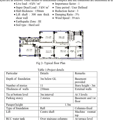
Architectural plan educational building with area 41.28 x 17.21m2 is shown in fig.2, constructed at Kolhapur, Maharashtra. Other considered during analysis are as follows. Other details of educational complex and site conditions are mentioned in table 1.
•Live load : 4 kN / m2
•Super Dead Load : 3 kN/ m2
•Slab thickness : 150mm
•Lift shaft : 300 mm thick shear wall
•Earthquake Zone : III
•Soil type : Hard soil
• Importance factor : 1
• Time period : User Defined
• Reduction factor : 3
• Damping Ratio : 5%
[image:2.595.123.511.310.722.2]• Wind Speed : 39 m/s
Fig 2- Typical floor Plan
Table 1-Project details
Particular Details Remarks Depth of foundation 3m below GL Basement
provided
Number of stories 11 Story height - 3m Thickness of walls 230mm External walls Tie at bottom level 3m interval At 3 levels Parking storey 2 stories Basement and 1st
floor Parapet height 1.5m
Type of foundation Raft Columns-fixed Lift Centre shaft Machine roomat
top
RCC water tank Over staircase columns At terrace level
Fig3 - Typical plan for all floors of buildings in ETAB .
Fig. 4 – Typical 3D Model showing the selected elenments.
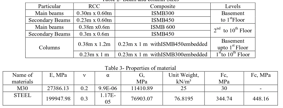
[image:3.595.56.543.421.608.2]With above data , the models were constructed, analysed and designed as per 456 and AISC code. The sizes of the different members in different model has been finalized as per strength as well as displacement requirements. The summary of final sizes for different elements are as follows. Table 2 shows of beam and column sizes used during design and analysis. Table 3 shows properties of materials used.
Table 2- Beam and column Sizes
Particular RCC Composite Levels Main beams 0.30m x 0.60m ISMB300 Basement
to 1stFloor Secondary Beams 0.23m x 0.60m ISMB450
Main beams 0.38m x0.6m ISMB 600
2nd to 10th Floor Secondary Beams 0.3m x 0.6m ISMB450
Columns 0.38m x 1.2m 0.23m x 1 m withISMB450embedded
Basement upto 1st Floor 0.23m x 1 m 0.23m x 1 m withISMB300embedded 1stto 10th Floor
Table 3- Properties of material Name of
materials
E, MPa ν α G, MPa
Unit Weight, kN/m³
Fc, MPa
Fc, MPa
M30 27386.13 0.2 9.9E-06 11410.89 25 30 - STEEL
199947.98 0.3
1.17E-05 76903.07 76.8195 344.74 448.16
V. Results of analysis in two different models
Following are the results of analysis. Comparison of parameters mentioned is tabulated in following tables. Response of Storey displacement and Drift for earthquake in X and Y direction is shown in fig 5 and 6 respectively. Results are presented for load combination 1.5(DL + LL + EQX/WL). Mass source is from load, which is, lumped at story levels. Contribution of dead load was 100% and from live load was 50% as live load is more than 3 kN/m2. In modal analysis, CQC method of combination was used and SRSS method was followed for directional combination. 12 modes were considered in modal analysis. Response spectrum method was used to apply earthquake load as per IS 1893 [5] and wind load as per IS 875[6].
Table 4-Roof displacement Load
combination
Parameter Type of Model RCC COMPOSITE DL+LL+EQX UX, mm 213.6 102.1
UZ, mm -14.1 -11.6
DL+LL+WLX
UX, mm 22 16.2 UY, mm -31.8 -18.4 UZ, mm -13.6 -11.5
[image:4.595.173.422.49.101.2]Table 5- shows Base shear, base moment, torsional moment due to earthquake and wind loads for the load combination dead load plus live load plus, earthquake or wind load. It is seen that the base shear is more in case of RCC than Composite structure. Vertical reaction is same in all the cases irrespective of earthquake/wind load applied in x and y direction. The torsional moment is observed to be same in both model. Bending moment about the transverse axis of load applied is more than the moment about self-direction. These moment is little bit more in case of earthquake load combinations.
Table 5-Base shear, base moment, torsion due to earthquake and wind load
Load Combination Parameter Type of model
RCC Composite DLLLEQX Base Shear ( in kN ) -6,357.68 -5,807
Base Moment ( in kN-m) 11,05,462 10,11,275 Torsion ( in kN-m) 55,710.01 50,977.71 DLLLWX Base Shear ( in kN ) -940.072 -940.072
[image:4.595.34.560.220.324.2]Base Moment ( in kN-m) 12,70,602 11,76,414 Torsion ( in kN-m) 8,806.779 8,806.779
Fig.5a and b shows the variation of drift along the storey height. It is seen that story drift is less in case of earthquake load and more in case of wind load.
Story drift in case of composite structure is less than RCC structure to both loads ( earthquake and wind ).
Fig 5a) - Response of story drift in X direction due to earthquake
Fig 5 b) - Response of story drift due to wind load along x direction respectively
Fig 6a and b shows variation of story shear along story height. Story shear is more in case of earthquake load than wind load. Story shear is less in case of composite structure.
Fig 6 a) - Response of story shear in X direction due to earthquake
Fig 6 b) - Response of story sheardue to wind load along x direction respectively
0 5 10 15
0 0.005 0.01
ST O REY LEV EL DRIFT
STORY DRIFT IN EQX
STORY DRIFT RCC EQX STORY DRIFT COMPOSITE EQX 0 5 10 15
0 0.0005 0.001 0.0015
ST O REY LEV EL DRIFT
STORY DRIFT IN WX
STORY DRIFT RCC WX STORY DRIFT COMPOSITE WX 0 5 10 15
-10000 -5000 0
ST
O
REY
LEV
EL
FORCE IN kN
STORY SHEAR IN EQX
STORY SHEAR RCC EQX STORY SHEAR COMPOSITE EQX 0 5 10 15
-1000 -500 0 ST
O
RY L
EVE
L
FORCE IN kN
STORY SHEAR IN WX
STORY SHEAR RCC WX
[image:4.595.29.568.380.567.2] [image:4.595.29.570.606.780.2]Table 6 : Max. values of different action of AF,SF, BM and TM for main beams at different story for RCC and Composite
Action Level Max value for RCC Max value for Composite Remark End 1 End 2 End 1 End 2
AF
Top 0 0 0 0 Axial force in beam is absent. Middle 0 0 0 0
basement 8.53 8.53 53.97 54.14
SF
Top -161.14 227.76 -156.21 211.51 Shear force decreases from top to bottom. Middle -49.72 340.46 -18.77 345.53
basement 47.57 87.21 120.64 141.42
BM
Top -160 -344.37 -197.96 -380.58 BM is higher in middle level beams . In top level
beam , BM is less. Middle 266.89 -736.45 281.51 -917.99
basement 234.60 -260.07 446.23 -537.42
TM
Top 30.10 -36.66 0.085 -0.099 TM is negligible for Bottom beams and max.
for top level beam Middle 31.88 -38.53 0.0685 -0.099
[image:5.595.98.497.299.480.2]basement -0.16 -0.16 -0.0213 -0.0074 All action are less for Composite structure
Table 7 : Max. values of different action of AF,SF, BM and TM for secondary beam at different story for RCC and Composite Action Level Max value for RCC Max value for Composite Remark
End 1 End 2 End 1 End 2
AF
Top 0 0 0 0 Axial force in beam is absent. Middle 0 0 0 0
basement -23.51 -23.51 -15.71 -15.71
SF
Top -145.80 169.32 -133.51 181.33 Shear force decreases from top to bottom. Middle -161.12 199.73 -149.49 194.08
basement -22.18 42.94 -19.39 35.14
BM
Top -211.19 -244.75 -135.68 -255.87 BM is higher in middle level beams . In top level
beam , BM is less. Middle -239.34 -309 -192.37 -285.85
basement 1.89 -39.98 0.49 -31.01
TM
Top -7.60 2.89 -0.045 0.0301 TM is negligible for Bottom beams and max.
for top level beam Middle -23.15 8.27 -0.17 0.0969
[image:5.595.106.492.513.695.2]basement -5.23 -5.23 -0.049 -0.049 All action are less for Composite structure
Table 8: Max. values of different action of AF,SF, BM and TM for column at different story for RCC and Composite Action Level Max value for RCC Max value for Composite Remark
End 1 End 2 End 1 End 2
AF
Top -634.32 -634.32 -526.26 -526.26 Axial force increase For RCC structure From top to bottom Middle -4119.35 -4119.35 -3578.95 -3578.95
basement -8408.75 -8408.75 -7708.61 -7708.61
SF
Top -32.60 -32.60 145.43 145.43 Shear force increase For RCC structure From top to bottom Middle 316.35 316.35 336.22 336.22
basement 682.26 682.26 511.13 511.13
BM
Top -410.5 -332.25 91.76 -235.46 BM increase For RCC structure From top to bottom Middle 226.77 -532.47 454.68 -301.82
basement 3255.90 2641.86 1355.96 972.61
TM
Top -1.89 -1.89 -2.63 -2.63 Negligible TM Middle 0.651 0.651 -2.24 -2.24
VI. CONCLUSION:
• The reduction in the self-weight of the Steel-Concrete Composite structure is reduced by is 9.48 % as compared to R.C.C. frame Structure.
• Shear forces in main beams in composite structure are increased by average 39.43% as compared to R.C.C. framed structure while in secondary beams in composite structure are reduced by average 14.39 % as compared to RCC framed structure.
• Bending moments in main beams in composite structure are increased 52.57% as compared to R.C.C. framed structure while in secondary beams in composite structure are reduced by average 28.93 % as compared to RCC framed structure.
• Axial forces in column in Composite framed structure have been reduced by average reduced by average 9.08 % as compared to RCC framed structure.
• Overall response of composite structure is better than RCC structure i.e. composite structure produces less displacement , resist more structure forces/ action. Earthquake response is more than wind load.
• In both the options the values of story displacements are within the permissible limits as per code limits. Still roof displacement and drift with earthquake in X and Y direction are less in Composite framed structure as to R.C.C. framed structure. This may be due to more ductility in case of Composite structure as compared to the R.C.C. which is best suited under the effect of lateral forces.
From the observations and concluding remark, it can be said that Steel-Concrete-Composite option is better than RCC for high rise building.
VII. REFERENCES:
1. [1] Institute for steel development & Growth, "B+G+40 Storied Residential Building with Steel-Concrete Composite Option” India, Dec 2007.
2. [2] M. Nageh, “How To Model and Design High Rise Building Using ETABs Program” Cairo 2007.
3. [3] M. Willford, A. Whittaker and R. Klemencic, “Recommendations for Seismic Design of High-Rise Buildings”
Council of Tall building and urban habitat Feb 2008.
4. [4] IS: 456, Code of practice for plain and reinforced concrete code of practice, Bureau of Indian Standards, New Delhi, 2000.
5. [5] IS: 1893, Criteria for earthquake resistant design of structures –general provisions for buildings, Part 1, Bureau of Indian Standards, New Delhi, 2002.
6. [6] IS: 875, “code of practice for design load (other than earthquake) for buildings and structures” Bureau of Indian Standards, New Delhi, 2002.
7. [7] IS: 800, Code of practice for general construction in steel, Bureau of Indian Standards, New Delhi, 2007.
8. [8] AISC 360-10, Specification of structural steel building, An American national standard, American Institute Of Steel Construction, Inc., 2005.
9. [9] IS: 11384, Code of practice for composite construction in structural steel and concrete, Bureau of Indian Standards, New Delhi, 1985.
Authors
First Author – Mr. Nitish A. Mohite , M.E. Civil Structural Engg. Student, Department of Civil Engineering, PVPIT, Budhgaon,
Sangli, MS, India , nitish.mohite5381@google.com
Second Author- Mr. P.K.Joshi, Associate Professor, Department of Civil Engineering, PVPIT, Budhgaon, Sangli, MS, India
pkjpvpit@gmail.com
Third Author- Dr. W. N. Deulkar, Associate Professor, Department of Civil Engineering, DYPCOET, Kolhapur, MS, India