Multi Touch: An Optical Approach (Comparison of
various techniques)
Rekha Singla, Mohit Malhotra, Dishti Agarwal, Deepti Chopra
Department of Computer Science, Maharaja Agrasen Institute of Technology (MAIT), GGSIPU
[image:1.612.329.541.472.663.2]Abstract- This paper will explain how the Multi-touch technology presents a wide range of new opportunities for interaction with graphical user interfaces, allowing expressive gestural control and fluid multi-user collaboration through relatively simple and inexpensive hardware and software configurations. We as the developers of the low cost multi-touch table draw our experience to provide the practical knowledge to build and deploy applications on the multi-touch surface. This will include the hardware and software requirements, comparison of various optical techniques and implementation of the multi-touch surface.
Index Terms- Multi-touch surfaces, Multi-touch technology, Optical Techniques
I. INTRODUCTION
s we all know, Multi-touch surfaces have found their way into the futuristic visions of human-computer interaction. It is a method of input on a touch screen that allows two or more fingers to be used on the screen at one time. In computing, multi-touch refers to a touch sensing surface's (track pad or touch screen) ability to recognize the presence of two or more points of contact with the surface
Now the question is why multi-touch? For the human computer interaction multi-touch has become a common interface thereby resulting in increase in productivity and one step ahead in creating an innovative interface.
Concept of multi-touch is not new to the world, it dated back to1970. Our multi-touch table is low cost and denotes a set of interaction techniques which allow computer users to control graphical applications with several fingers and consists of a touch screen (e.g., computer display, table and wall) or touchpad, as well as software that recognize multiple simultaneous touch points, as opposed to the other touch screens.
There are numerous ways to construct multi touch surfaces:-
Resistance Based Touch Surfaces: It is made up of two electrical resistive layers separated by thin air space. The layers have electrodes which are facing each other, when a contact is made both layers are pressed together to give the precise location.
Capacitance Based Touch Surfaces: It consists of an insulator coated with a transparent conductor such as Indium Tin Oxide. When we touch the surface it results in distortion of electrostatic field, measurable as change in capacitance used for sensing the touch.
Surface Wave Touch Surfaces: In this technique transmitting and receiving piezoelectric transducers, for both the X- and Y axis, are mounted on a faceplate and ultra-sonic waves on a glass surface are created and then directed by reflectors.
Optical Touch Surfaces: Optical Touch technology is an economical way to add touch capability to any display. It accommodates multiple touch points with a high degree of precision and user can touch any part of the screen with any material- finger, pen or a stylus. There are several ways to make a multi-touch surface. But this research paper will focus on Optical techniques and implementation of the multi-touch table using the front diffused illumination technique along with the comparison of various optical techniques. The main focus will be on optical techniques since they are the easiest and most cost effective for the average person to create.
II. OPTICAL TECHNIQUES
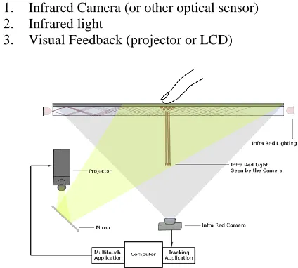
Optical Techniques provide the most cost effective way of implementing multi touch. Each technique utilizes 3 main components:
1. Infrared Camera (or other optical sensor) 2. Infrared light
3. Visual Feedback (projector or LCD)
Fig 1: Illustration of basic structure of touch surface
An infrared camera is pointed at the touch surface to detect fingers/objects that touches the surface. Infrared light is used to so as to differentiate between visual images and the objects/fingers. Most systems have a visual feedback system
where an image from a projector or LCD is projected or placed below the touch surface. A tracking application uses the camera image to track and create touch coordinates.
Major optical techniques to construct touch surfaces:
Frustrated Total Internal Reflection (i.e. Perceptive Pixels)
Rear Diffused Illumination (i.e. Microsoft Surface)
Front Diffused Illumination
Diffused Surface Illumination
Laser Light Plane
LED Light Plane
1. FRUSTRATED TOTAL INTERNAL REFLECTION
FTIR uses the phenomenon of Total Internal Reflection in which infrared lights are placed adjacent to the edges (sides) of an acrylic panel. When the user touches the acrylic surface, the infrared light is “frustrated” which causes the light to escape internal reflection and scatter downwards which is scanned by an infrared camera (modified webcam).
Fig 2: Illustration of Frustrated Total Internal Reflection
2. REAR DIFFUSED ILLUMINATION MULTITOUCH TECHNIQUE
In Rear DI, infrared light illuminates the screen from below the touch surface. A diffuser needs to be placed on top/bottom of the touch surface. When the user touches the surface, the infrared light hits his finger and is reflected downward and sensed by an infrared camera below the surface.
Fig 3: Illustration of Rear Diffused Illumination Technique
3. FRONT DIFFUSED ILLUMINATION MULTITOUCH TECHNIQUE
[image:2.612.326.563.390.527.2]In Front DI, infrared light is shown from above the touch surface. A diffuser is placed on top/ bottom of the touch surface. When the user touches the surface, a shadow is formed under it and this is seen by an infrared camera placed below the surface.
Fig 4: Demonstration of Front Diffused Illumination
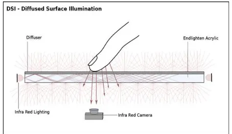
4. DIFFUSED SURFACE ILLUMINATION
Like FTIR, in DSI infrared light is placed adjacent to the edges of an acrylic panel, directed towards the inside. It uses a special acrylic with small particles inside it, which act like hundreds of small mirrors for evenly distributing the light. On touching the diffuser, the light escapes out of the surface and thus the object/finger can be seen by the camera.
Fig 5: Illustration of DSI (Diffused Surface Illumination)
5. LASER LIGHT PLANE MULTITOUCH TECHNIQUE
Fig 6: Demonstration of Laser Light Plane Technique
6. LED LIGHT PLANE MULTITOUCH TECHNIQUE
[image:3.612.326.563.57.512.2]LED-LP, alike LLP forms a plane of light above the surface. In this narrow angle LEDs are used. The LEDs are placed just above the touch surface in order to create a plane of light. When a finger makes a contact with the light plane, it is seen by a infrared camera below the surface.
Fig 7: Illustration of LED Light Plane Technique
III. COMPARISON OF MULTI TOUCH TECHNIQUES
[image:3.612.61.275.58.192.2]Even though FTIR is more popular than other techniques, there is no best technique. Each technique has its pros and cons as listed below.
Table 1: FTIR
Advantages Disadvantages
In FTIR an enclosed box is not required
Soldering is required for making the LED frame The Blobs have strong
contrast
It Requires a compliant surface
(silicone rubber) for proper application
It allows for varying the blob pressure on the surface.
It Cannot recognize the objects or fiducial
markers
It can be used with something as pen tip since it uses a compliant surface.
It Cannot use a glass surface only the acrylic sheet is required for FTIR.
Table 2: Rear DI
Advantages Disadvantages
Just a diffuser/projection surface on
Top/bottom is used, no need for the compliant surface.
Even illumination is difficult to get
Any transparent material (glass or acrylic) can be used.
The lower contrast of blobs is harder to
pick up by software. LED frame not required. More chances of
detecting false blobs. No soldering required. Requires enclosed box.
Table 3: Front DI
Advantages Disadvantages
Just a diffuser/projection surface on
Top/bottom is used, no need for the compliant surface.
Objects and fiducials cannot be tracked.
Any transparent material (glass or acrylic) can be used.
It relies heavily on ambient lighting environment
[image:3.612.59.277.309.445.2]LED frame not required More chances of detecting false blobs.
Table 4: DSI
Advantages Disadvantages
Compliant surface not required.
Cost of Enlighten Acrylic is more than
regular acrylic Easy to switch back and
forth
between DI (DSI) and FTIR
Lower contrast of blobs is harder to
pick up by software compared to FTIR and LLP.
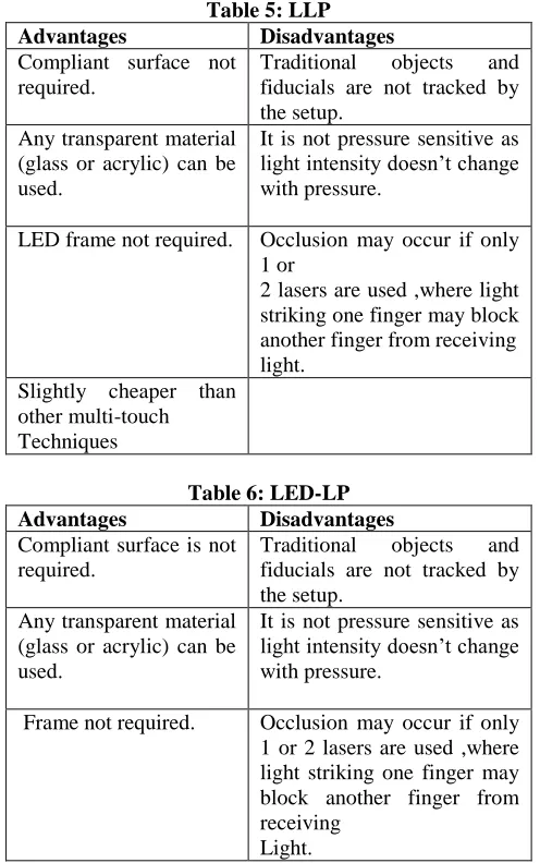
Table 5: LLP
Advantages Disadvantages
Compliant surface not required.
Traditional objects and fiducials are not tracked by the setup.
Any transparent material (glass or acrylic) can be used.
It is not pressure sensitive as light intensity doesn’t change with pressure.
LED frame not required. Occlusion may occur if only 1 or
2 lasers are used ,where light striking one finger may block another finger from receiving light.
Slightly cheaper than other multi-touch Techniques
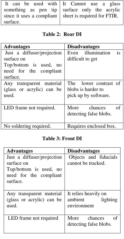
Table 6: LED-LP
Advantages Disadvantages
Compliant surface is not required.
Traditional objects and fiducials are not tracked by the setup.
Any transparent material (glass or acrylic) can be used.
It is not pressure sensitive as light intensity doesn’t change with pressure.
Frame not required. Occlusion may occur if only 1 or 2 lasers are used ,where light striking one finger may block another finger from receiving
Light.
IV. IMPLEMENTING A LOW COST TOUCH TABLE-FRONT
DIFFUSED ILLUMINATION TECHNIQUE 1. Hardware Requirements
A. Infrared Illumination
Optical methods for multi touch require an infrared light source. Achieving the correct infrared illumination is challenging and requires a good knowledge of both the different methods of illuminating a surface and the various types of IR LEDs (5mm, 3mm, SMD (synchronous mirror delay)) that are available. All the IR-based set-ups employ light-emitting diodes (LEDs) as light sources. Commonly used types of IR LEDs include Osram SFH4250 (SMD) and Osram SFH485 (5 mm). Whether SMD devices or standard LEDs are more appropriate depends on various factors; say for example, if the LEDs are to be placed along the rim of an acrylic glass plate, SMDs can be used, as it is possible to simply attach them to the rim with instant glue.
B. Cameras
Optical Techniques rely on cameras to detect fingers touching the surface. For functional surface, a camera set-up must be capable of sensing light in the near-IR spectrum.
Although challenging, the correct choice of camera is essential to gain high camera-signal quality required for a multi-touch surface. Camera sensors, capable of detecting IR light are required. When choosing a camera, sensors must be sensitive to wavelength of IR light. Web cameras contain an infrared filter to block ambient infrared light and must be removed. Although often it is either glued on to the lens or applied as a coating on the camera and must be scratched from the lens.
C. Projectors
Rear projection is generally used for displaying the actual image on the surface; but a number of factors must be considered when deciding upon an appropriate projector. Major factor is display resolution. The necessary projection resolution is strongly application dependent; however, a resolution of at least 1024_768 pixels (XGA) is usually sufficient.
D. Compliant Surfaces and Projection Screens
Multi touch set-up is comprised of a layer of acrylic or glass sheet augmented with a frame.
Compliant layer: A plain acrylic surface requires the user to apply significant pressure to get a responsive tracking. The use of a compliant surface overcomes this problem. Applying an additional layer on top of the acrylic or glass material greatly improves the sensitivity of the surface.
Projection layer: Depending on what material is used (silicone or latex), a different projection screen must be chosen. The main requirement is that an air gap should be achievable between the two layers when the screen chosen is pressed against the compliant surface.
2. Software Requirements
A. OpenCV (Open Source Computer Vision Library)
It is a library of programming functions aimed at real-time computer vision. It has interfaces for C++, C, Python and Java and supports a number of OS- Windows, Linux, MAC, and Android. OpenCV was designed to achieve computational efficiency and with a strong focus on real-time applications.
B. CCV (Community Core Vision (CCV)
CCV is a tracking application (Main Finger Tracking Application) – needed to track fingers and for calibration. It supports Windows, Linux, and Mac.
C. TUIO (Tangible User Interface Object) Mouse
Driver
It is a protocol used for communicating the location (X and Y coordinates), size, and relative velocity of blobs.
D. Flash Player Projector
4. Hardware Setup:
Fig 8: Multi Touch Panel
The Glass (8 mm) was placed and Tracing Paper was placed on the surface of the glass in order to display the projected image. An infrared camera- (Intex Night Vision Camera) was pointed at the touch surface to detect when fingers/objects that touches the surface. Infrared light – ambient light was used to distinguish between a visual image on the touch surface and the objects/fingers being tracked. Panasonic Projector was projected or placed below the touch surface. Mirror was placed at an angle of 45° (approx.) in front of the projector to redirect the beamed image from the projector to the glass surface. The camera was also connected to the computer and a tracking application (CCV) used the camera image to track and create touch coordinates.
4. Camera Modification: Removal of IR Blocking Filter Materials required:
1. Webcam 2. Screw Driver 3. Blade
Modification of a webcam was necessary to detect the IR blobs that were generated by our fingers. IR is not visible to the human eye, neither is it to most of the webcams. In order for a webcam to detect IR light, IR blocking filter has to be removed from it. In our case the IR-block filter was painted on the lens and could be scratched off. In most cases, it’s impossible to remove the IR-block filter, without damaging the lens, as it is glued to the lens. In that case, it is wise to replace the default lens with a special lens that doesn’t have an IR-block filter attached to it.
5. CCV Installation and Calibration:
[image:5.612.47.288.63.236.2]Latest version of Community Core Vision was downloaded. The camera was attached to computer and the Community Core Vision (CCV) application was launched.Settings were changed to detect the fingers and calibration screen was opened by pressing “c” on keyboard. After calibrating test that the surface detects all your fingers.
[image:5.612.344.543.412.739.2]Fig 9: Calibration of the surface
Fig 10: Testing for successful calibration
6. Working on multi touch
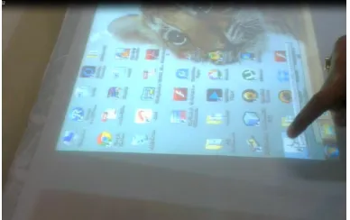
The laptop was connected to the projector and Windows-7 desktop screen was displayed. One can open different applications and can even type documents using touch instead of a keyboard.
Fig 11: Clicking icons using multi touch
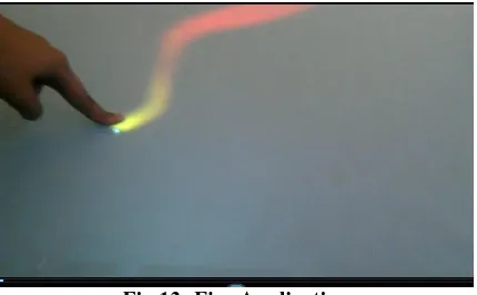
[image:5.612.348.542.444.566.2] [image:5.612.346.542.587.718.2]Also Flash application was created and opened using Flash Projector. Tracking information from the CCV was send to the flash projector using one of the following:
(CCV 1.1 or below), turn on Send TUIO in CCV
(CCV 1.2+), turn on Flash XML in CCV
[image:6.612.61.276.173.306.2]The screen was checked for input and location. If the system is not pointing to the correct location calibration has to be redone.
Fig 13: Fire Application
V. CONCLUSION
This report covers areas including but not limited to different methods and tools to build a multi-touch system and its working. The setup implemented by us is fairly simple. Literally every setup differs so there is a need to play around with most of the steps to find what works best for the setup. The basic concepts covered here will always apply. Similarly other techniques can be implemented practically. We also conclude that there is no best technique and each technique has its pros on cons. One can select which one to use depending upon the time, resources and conditions.
Multi-touch technology with computationally enhanced surfaces has attracted considerable attention in recent years as it greatly improves human-computer interaction. Optical approach for touch surface uses image processing to determine the locations velocity of the interacting object. Infrared illumination and simple setups mean that these systems can potentially be very robust. Implementation of frustrated total internal reflection
(FTIR) and diffused illumination (DI), have enabled low-cost development of touch surfaces. Laser-light plane and diffused-screen illumination have their own advantages.
REFERENCES
[1] Jenna Shanis, Alan Hedge. An Exploration Of Multi touch Technology [2] Johannes Schöning, Jonathan Hooky, NimaMotamedi, Patrick Oliviery,
Florian Echtler, Peter Brandlz, Laurence Mullern, Florian Daiber, OtmarHilliges, Markus Loechtefeld, Tim Roth, DominikSchmidt,Ulrich von Zadow. DFKI GmbH, Germany; Newcastle University, UK; Simon Fraser University, Canada; Technical University Munich, Germany; Upper Austria University of Applied Sciences, Austria; University of Amsterdam, Netherlands; University of Munich, Germany; University of Zurich, Switzerland; University of Lancaster, UK; Archimedes Solutions GmbH, Germany.
[3] Harry van der Veen, callsign Gravano. FTIR multi-touch display Florian Echtler, Thomas Pototschnig, GudrunKlinker. An LED-based Multitouch
Sensor for LCD Screens,
TechnischeUniversit¨atM¨unchenInstitutf¨urInformatik I16 Boltzmannstr. 3, 85747 Garching, Germany.
[4] Johannes Schöning?, Peter Brandl, Florian Daiber, Florian Echtler, OtmarHilliges, Jonathan Hook, Markus Löchtefeld, NimaMotamedi, Laurence Muller, Patrick Olivier, Tim Roth, Ulrich von Zadow . Multi-Touch Surfaces: A Technical Guide
[5] http://en.wikipedia.org/wiki/Multi-touch [6] www.peauproductions.com
[7] http://www.perada-magazine.eu/view.php?article=002864-2010-03-29 [8] http://ccv.nuigroup.com/
[9] http://hcimultitouch.wordpress.com/2010/11/03/the-basic-technics/ [10] http://www.adobe.com/support/flashplayer/downloads.html
AUTHORS
Rekha Singla, Associate Professor, department of CSE, MAIT, GGSIPU, [email protected]
Mohit Malhotra, Student B.Tech, department of CSE, MAIT, GGSIPU, [email protected]
Dishti Agarwal, Student B.Tech, department of CSE, MAIT, GGSIPU, [email protected]
Deepti Chopra, Student B.Tech, department of CSE, MAIT, GGSIPU, [email protected]