Frequency Control Scheme Using Integrated Grid
Inverter for Wind Mill Applications
Dr. S. Titus
*, B.J.Vinothbabu
**, I. Maria Anton Nishanth
****
Member, IEEE, Department of EEE, MAM college of Engineering, Trichirappalli, India **
Department of EEE, MAM college of Engineering Trichirappalli, India ***
Department of EEE, MAM college of Engineering Trichirappalli, India
Abstract- Wind is a copious vital source of energy which is complimentary and a fabulous gift of Mother Nature. The escalating levels of wind generation have resulted in an urgent appraisal of their impact on frequency control of power system. Despite the consequences of wind turbine technology, The main intention of this paper is to counterpart the generated frequency from the existing system along with the GRID side frequency which has an unremitting variation due to the loads connected besides the GRID. This frequency disparity is the major concern in today's renewable energy system and is particularly true in portable wind mill applications connected with the grid. So a frequency control scheme using integrated grid inverter for such wind mill applications is being discussed in this paper.
Index Terms- wind generation, frequency control, grid issues, integrated grid inverter.
I. INTRODUCTION
he development of wind power in India began in the 1990s, and has significantly increased in the last few years [1]. Although a relative newcomer to the wind industry compared with Denmark or the United States, India has the fifth largest installed wind power capacity in the world [2].
In India, demand is more whereas generation is less. Even if we generate enough wind energy, it cannot be effectively utilized [3] due to the technical challenges such as grid quality [4] as well as wind turbine issues [5], So, the integration of wind generation with an existing electricity system depends on number of factors like technical as well as regulatory. The grid codes for wind, in general deals with the following technical requirements like Active power control, Frequency, Voltage and reactive power issues, Protection, Power quality issues like flicker, harmonics etc [6].
II. ELDERLYSYSTEMISSUES
In general, the wind generation is described in two levels such as small wind generators and large wind generators. A small wind generator is connected to an isolated load and the large wind generator is connected with the grid.
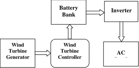
[image:1.612.320.559.256.373.2]The small wind electric generator (SWEG) is an implemented project to produce a decentralized power supply in remote locations of India which is directly connected to AC load [7].
Figure 1. Schematic of a typical SWEG project
In order to maintain a constant output voltage as well as frequency, the storage equipments like battery banks, capacitor banks and etc are used, which delivers a constant dc output voltage to the inverter which converts a fixed dc to a variable ac output voltage and it is connected with the load [8] [9].
Also, the regulation of ac voltage and frequency to the load is done via an algorithm proposed in [10]. Such kind of wind generators do not have sufficient scheme towards frequency control when connected across a grid and also these are very expensive as compared to that of large wind electric generators.
In common, large wind generators are connected with the grid via proper control devices. Due to wind fluctuations, the wind generator is not suitable for use because its output varies with amplitude and frequency. So, these methods use many techniques to control the fluctuated voltage and frequency in the wind mill rotor side itself which minimizes the overall power fluctuations. The most familiar Doubly Fed Induction Generator (DFIG) drive is used to balance the power quality parameters to an extent [11]. This DFIG drive is enhanced by Wind Turbine Generators (WTG). But, due to certain constraints in current limit, the DFIG WTG needs some design modification such as increase in DFIG converter rating, as required [12].
The voltage and frequency control of wind generator is done through vector controlled PWM voltage source inverter for both load and wind variation but the control
T
Battery
Bank Inverter
AC Load
Wind Turbine Controller Wind
ISSN 2250-3153
scheme derived is complicated and number of controlling devices is more [13]. Also, the wind frequency control is achieved through variable speed wind turbines (VSWTs). This control has energy storage device to enhance the performance of wind output [14].
In all these above mentioned elderly methods the control strategy for frequency fluctuation in the grid side is not focused highly.
During a sudden change in the grid frequency, the generator feeds excess power to the grid through an inverter or converter, which is isolated from the grid to prevent the entire system from major crisis such as abnormalities in the transmission line parameters. Also, this causes a foremost damage in wind generator as well as other accessories connected along with it. Many isolated grids are in practice to avoid such frequency collapse and other power quality issues which is economically not appropriate.
III. CONVENTIONALSYSTEMSIMULINK MODEL
The grid frequency fluctuates according to various loads connected besides the grid which in order fabricates a local circulating current in between the grid and the inverter. This circulating current will not depart to the load and creates a major issue in the form of heat. It destroys the entire system connected with the existing structure [15]. This frequency mismatch is the major concern in today's renewable energy system while connected with the grid.
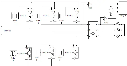
The issues described above are conferred with a simulink example as shown in Fig 2. Under no load condition, the three phase inverter output voltage of 400 V and frequency of 50 Hz is connected to the grid, which also consists of the same voltage and frequency. Fig 3 and Fig 4 indicates the inverter output voltage and grid voltage for phase AB respectively. In this case, both the grid frequency as well as the inverter frequency is same and it is perfectly matched which is shown in Fig 5. In this case there is no frequency mismatch issue until the grid frequency fluctuates.
[image:2.612.316.557.74.509.2] [image:2.612.317.559.81.191.2]Figure 2. Simulink model for conventional system
Figure 3. Simulation result for inverter voltage Vab
Figure 4. Simulation result for grid voltage Vab
Figure 5. Simulation result for same frequency in grid and inverter
[image:2.612.55.297.571.698.2]Figure 6. Simulation result for grid voltage Vab
Figure 7. Simulation result for frequency mismatch in grid and inverter
400V, 50Hz
10 Cycles for 0.2seconds
50 Hertz
Vo
lta
g
e
in
v
o
lts
Time in seconds
Vo
lta
g
e
in
v
o
lts
10 Cycles for 0.2seconds
50 Hertz
Time in seconds
400V, 50Hz
Vo
lta
g
e
in
v
o
lts
10 Cycles for 0.2seconds
50 Hertz
Time in seconds
Time in seconds
Vo
lta
g
e
in
v
o
lts
Vo
lta
g
e
in
v
o
lts
Time in seconds
400V, 45 Hz
9 Cycles for 0.2seconds
Under load condition, whenever there is an increase in the load inductance then there will be a frequency mismatch.
For example - impedance of 500 ohm, resistance of 100 ohm, inductive reactance of 300 ohm and inductance of 1.05 Henry will reduce the grid frequency to 45 Hz, [16] which causes a frequency mismatch between the grid and the inverter.
Fig 7 confirms the phase displacement between both the grid as well as inverter frequency. Fig 3 explains the inverter frequency with 50 numbers of cycles per second and Fig 6 shows grid frequency with 45 numbers of cycles per second in which the phase displacement between them is 5 numbers of cycles per second. It is understood by adding grid and inverter voltage as shown in Fig 5 and 7. Hence all the above results confirms the issues in an existing system and thus to avoid such problems we propose an integrated grid inverter which helps to maintain the system stability always.
IV. TESTSYSTEMMODEL
The test system specification is as follows Wind velocity – 3 to 8 meter per second. Wind Generator (G) – 24 Vdc, 500 W, 300 rpm. Step UP Chopper – 24 / 400 Vdc.
[image:3.612.316.563.275.592.2] Grid Inverter – 400 Vdc / 400 Vac (three phase). Grid – 400 Vac, 50 Hz, 10 KW.
Figure 6. Block diagram of Test system.
V. SIMULINKMODELOFTESTSYSTEM
An AR-500W portable wind mill is used to experiment the frequency control scheme. The rated electrical power is 500 w at 8.2 m/s. A 24 volt dc generator of speed 300 rpm is used to convert the wind energy into electrical energy. The generated electrical energy is stored in a battery from which a constant dc output voltage is delivered to the inverter via step up chopper (24 / 400 Vdc).
A three phase integrated grid inverter with 180 degree mode of conduction is designed for this test system. This inverter with an input of 400 V dc delivers a three
phase output of 400 Vac to the grid. A feedback from the grid (voltage and frequency) is fed to a pulse generator through which the inverter switches are controlled.
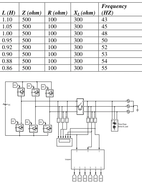
Under normal operating condition there is no change in the grid frequency. While there is an increase in the load inductance, then a lagging power factor occurs which cause a change in grid frequency. The frequency deviations under various load conditions are listed in Table1 [16]. The change in grid frequency signal is given to the pulse generator which is compared with a reference signal. The compared signals generate six different pulses to the inverter. This operates the inverter for three phase 400V ac output with frequency similar to grid frequency. The entire test model is designed in MATLAB / SIMULINK environment as pictured in Fig 7.
TABLE 1. FREQUENCY DEVIATIONS IN GRID
L (H) Z (ohm) R (ohm) XL (ohm)
Frequency (HZ)
1.10 500 100 300 43
1.05 500 100 300 45
1.00 500 100 300 48
0.95 500 100 300 50
0.92 500 100 300 52
0.90 500 100 300 53
0.88 500 100 300 54
0.86 500 100 300 55
v
+
-v
+
-v
+
-v
+
-v
+
-v
+ -A
B
C a
b
c
A B C
Three-Phase Series RL Load
va vb vc
s1 s3 s5 s6 s4 s2
Subsystem
[A2] [A4] [A6] [A5] [A3] [A1] [A5]
[A2]
[A4] [A6]
[A3] [A1]
DC
g C
E
6
g C
E
5
g C
E
4
g C
E
3
g C
E
2
g C
E
1
Figure 7. Simulink model of Test System
VI. RESULTANDDISCUSSION
The Fig 7 indicates that the number of cycles per second in the grid as well as number of cycles per second in the inverter is equal under different load conditions at various time periods. Fig 8 describes the result for phase AB output frequency matching of both inverter and grid.
G
Step Up
Chopper Inverter
Controller
[image:3.612.70.279.409.537.2]ISSN 2250-3153
[image:4.612.319.560.73.392.2]Test system is designed such that for every 0.2 seconds the grid frequency changes according to various loads. Hence the Inverter output frequency also changes. The result for frequency matching is shown in Table 2. With this type of system the inverter could always be connected to the grid without isolating the inverter circuit from the grid even when there is a change in frequency. Observably the Test system reduces the issues of conventional system.
TABLE 2. INVERTER–GRID FREQUENCY MAPPING
Simulation
Time in
seconds
Load Inductance L(H)
Grid Frequency in Hz
Inverter Frequency in Hz
0 to 0.2 1.10 43 43
0.2 to 0.4 1.05 45 45
0.4 to 0.6 1.00 48 48
0.6 to 0.8 0.95 50 50
0.8 to 1.0 0.92 52 52
1.0 to 1.2 0.90 53 53
1.2 to 1.4 0.88 54 54
1.4 to 1.6 0.86 55 55
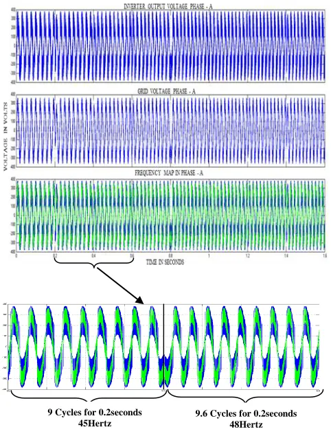
Figure 8. Simulation result for frequency match between inverter and grid
Figure 9. Simulation results for frequency match in phase A.
From Table 2, the time interval of 0.4 to 0.6 seconds the load inductance varies which impacts the change in the grid frequency from 45 to 48 Hertz. Due to this sudden change in the grid frequency, causes unstable condition in the grid. To overcome this crisis, the proposed inverter design corrects the frequency mismatch which is shown in fig 9. According to the grid frequency signal received, the inverter operates in order to match the grid frequency. This makes the system to perform from unstable to stable condition. Therefore the performance of grid as well as inverter frequency has been improved.
VII. CONCLUSION
From above discussion, number of cycles per second in the grid and number of cycles per second in the inverter is equal under various load conditions. This helps to connect the inverter along with the grid always in order to avoid the frequency mismatch. So, the wind power generation could be utilized effectively which reduces the demand to a maximum level. Hence the setback in the foregoing method is met by successfully mapping the frequencies between the grid as well as the inverter.
Grid
Volt
age
in
volts
ph
a
se
C
ph
a
se
B
ph
a
se
A
45 Hertz
50 Hertz
53 Hertz
55 Hertz 54
Hertz 52
Hertz 48
Hertz 43
Hertz
9 Cycles for 0.2seconds 45Hertz
9.6 Cycles for 0.2seconds 48Hertz
Inv
er
ter
o
utput
Vo
lt
a
g
e
[v
o
lt
s]
ph
a
se
C
ph
a
se
B
ph
a
se
A
54 Hertz 52
Hertz 48
Hertz 43
[image:4.612.45.297.186.693.2]REFERENCES
[1] http://www.chevron.com/globalissues/emergingenergy/?gclid=CI2 Eicqiqa4CFccc6wodkzjESQ
[2] http://en.wikipedia.org/wiki/Wind_power_in_India
[3] G. M. Joselin Herbert, S. Iniyan, Ranko Goic, “Performance, reliability of wind farm in a developing country,” Renewable Energy 35 (2010), 2739 – 2751, Elsevier LTD.
[4] Narasimhan Santhanam, “Wind Energy in India Potential and Challenges,” volume 5, issue 2, October 2011, RE Feature.
[5] G. M. Joselin Herbert, S. Iniyan, E. Sreevalsan, S. Rajapandian, “A Review of Wind Energy Technologies,” Science Direct, Renewable and Sustainable Energy Reviews 2007, (1117 – 1145).
[6] http://www.cwet.tn.nic.in/Hindi/Docu/Wind_grid_code_for_India%20 .pdf [7] M. R. Nouni, S. C. Mullick, T.C. Kandpil, “Techno – Economics of Small
Wind Electric Generator Projects for Decentralised Power Supply in India,” Energy Policy 35 (2007) 2491 – 2506, Elsevier LTD.
[8] Wei Xian, Weijia Yuan, Yu Yan, T. A. Coombs, “Minimise Frequency Fluctuations of Isolated Power System with Wind Farm by using Super Conducting Magnetic Energy Storage,” PEDS2009.
[9] Muhammad Khalid, Andrey V. Savkil, “Model Predictive Control for Wind Power Generation Smoothing with Controlled Battery Storage,” IEEE Conference on Decission and control and 28th Chinese Control Conference,
December 16 – 18, 2009.
[10] Bhim Singh, Shailendra Sharma, “Stand – Alone Wind Energy Conversion System With an Asynchronous Generator,” Journal of Power Electronics, volume 10, No. 5 , September 2010.
[11] J.B. Ekanayake, L. Holdsworts, S. Wu, N. Jenkins, “Dynamic Modelling of Doubly Fed Induction Generator Wind Turbines,” IEEE Transaction on Power System, volume 18, No. 2, 803 – 809, may 2003.
[12] Gillian Lalor, Alan Mullane, Mark O’ Malley,”Frequency Control and Wind Turbine Technologies,” IEEE transaction on Power Systems, volume 20, No. 4, November 2005.
[13] MD. Enamuel Haque, Michael Negnevitsky, Kashem M. muttaqi, “A Novel Control Strategy for a Variable Speed Wind Turbine With a Permanent Magnet Synchronous Generator,” IEEE Transaction on Industry Application, volume 46, No. 1, January / February 2010.
[14] M. saleh, H. Bevrani, “Frequency Regulation Support by Variable Speed Wind Turbione and SMES,” Worl Acadamy of Science, Engineering and Technology 65, 2010.
[15] B. L. Theraja, A. K. Theraja, “A Text Book of Electrical Technology volume 2 AC and DC Machines,” S. Chand & Company LTD, New Delhi, 2005.
[16] V.K. Mehta, Rohit Mehta, “Principles of Power System,” S. Chand and Company LTD, New Delhi, 2005
AUTHORS
First Author – Dr. S. Titus, Member, IEEE, Department of EEE MAM college of Engineering, Trichirappalli, India, e-mail: [email protected]
Second Author – B.J.Vinothbabu, Department of EEE, MAM college of Engineering Trichirappalli, India, e-mail: