Design and Implementation of Single Phase Fully
Controlled Bridge Rectifier Using PIC Microcontroller
C.B. Erney Fabian*, P.P. Diego Alejandro*, G.A. Franklin Meer*
*
Department of Electromechanical Engineering, Santander Paula Francisco University
Abstract- In order to advance in the firing angle control of thyristors in the single phase fully controlled bridge rectifiers through the actual technology this paper presents a method of obtaining a regulated dc voltage through digital control. This lineal dc voltage is obtained through the control of phase angle of thyristors with a PIC microcontroller of low gamma. The algorithm control is programmed in C language and the results are verified for different types of load.
Index Terms- C language , fully controlled bridge rectifier ,Microcontroller, Phase Angle.
I. INTRODUCTION
he firing control of thyristors for single phase fully controlled rectifiers is based mainly in two strategies of control, the first is cosine control and the second is the already meet ramp type control these strategies are explained in [1].
These forms of firing are implemented through an ample circuitry which occupy large space in electronics targets besides possess a high cost. In order to contribute in the improvement of firing control of thyristors, this paper presents a strategy of digital control to control the firing phase angle of thyristors in single phase fully controlled bridge rectifiers implemented through a PIC microcontroller.
II. PROPOSED DIGITAL CONTROL
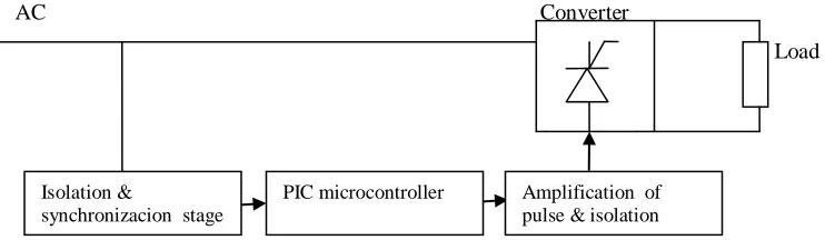
Digital control proposed and implemented in this research work consists in the activation adequate of thyristors in single phase fully controlled rectifiers through an algorithm based in the logic necessary to achieve a correct performance of converter. Figure 1 shows the block diagram of control circuit. Microcontroller is used to control one to one the phase angles of thyristors, to read an external interruption from zero crossing detector circuit and too is used to read a analog signal proportioned for a potentiometer which will be read for the microcontroller and according to this reading will be obtained a phase angle determined.
AC Converter
Load
T
Isolation &
synchronizacion stage
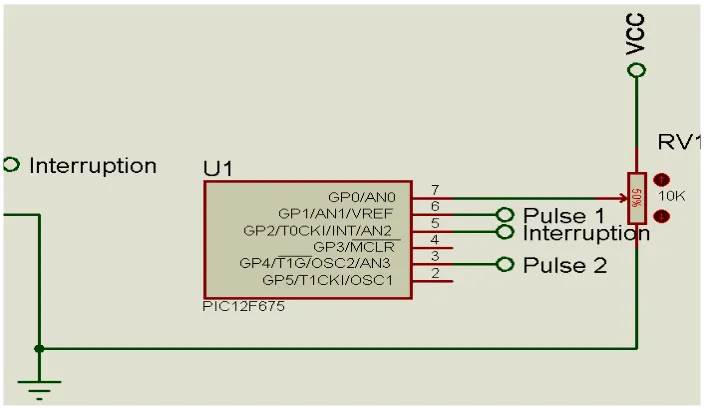
[image:1.612.77.448.556.664.2]A. Microcontroller
Microcontroller PIC12f675 is used to implement the development of control algorithm. An analogous input and a digital input in addition to the two digital outputs for the control pulses are used in the microcontroller. The microcontroller performs its operation using 5v of supply.
B. Software
Control algorithm is developed in embedded C language. The compilation of executable software code is achieved using a test version of the CCS compiler.
IV. METHODOLOGY
A. Control Voltage 0-5 V
The control voltage of firing angle of thyristors will be from 0 to 5v, a voltage of zero for 0° and a voltage of five for 180°, this voltage will be provided through the reading of an existent voltage in a potentiometer fed to 5 volts.
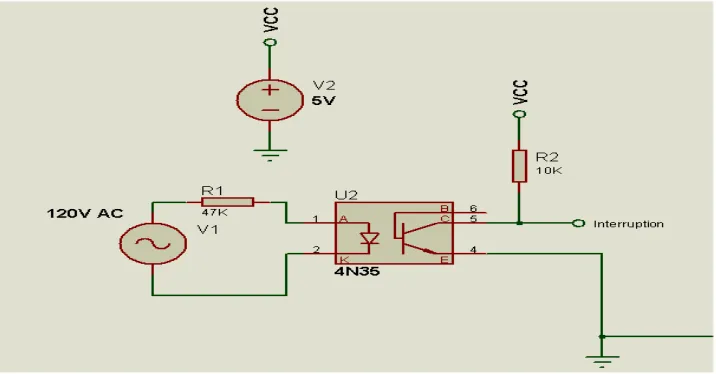
B. Zero Crossing Detector Circuit
[image:2.612.128.486.399.586.2]Zero crossing detector circuit is designed to obtain the digital signal which will indicate to microcontroller the existence of an external interruption. Zero crossing detector circuit used is shown in Fig.2
Fig. 2 Zero crossing detector circuit
C. PIC Microcontroller
PIC Microcontroller uses a analog port for reading a analog signal of a potentiometer with a magnitude between 0 to 5 volts.
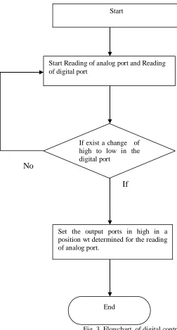
No
[image:4.612.117.369.62.530.2]If
Fig. 3 Flowchart of digital control
E. Production of Control Pulses
The production of control pulses of thyristors is governed for the algorithm of control. The duration of each control pulse in a high logic state is same to 50us and its position is varied in a axis t from 0 to 8.33ms. This instant determined will depend on the analog reading of voltage existent in the potentiometer which will be realized each time that exists an external interruption in the microcontroller, for this reading it uses the ADC (analog to digital converter) of 16 bits of microcontroller. This analog reading is converted in a digital measure which is after multiplied by a factor of adjust to obtain the instant of time determined to activate any thyristor.
(1)
Where:
Set the output ports in high in a position wt determined for the reading of analog port.
Start Reading of analog port and Reading of digital port
End
If exist a change of high to low in the digital port
X, is an adjustment factor.
[image:5.612.159.454.90.213.2], is the firing angle of each thyristor.
Fig. 4 Control Pulses for firing angle, α=90° with sine wave of the source
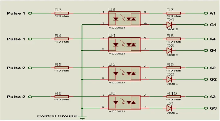
F. Stage of Isolation
The stage of isolation is compound for four optocouplers, that fulfill the function of separating the power stage of control stage.
Fig. 5 Circuit of isolation stage
G. Stage of Power
[image:5.612.129.484.316.512.2]Fig. 6 Circuit of power stage
V. RESULT AND DISCUSSION
The strategy of implemented control presented the following results, which fulfills the objective of providing controlled dc output voltage for different types of load.
A. Bridge Rectifier Output for Resistive Load 1) for firing angle, α=30°
The figure shows the waveform of output voltage of the bridge rectifier with resistive load. The value of average output voltage for this firing angle is given in table I.
Fig. 7 Waveform of output voltage for firing angle, α=30°
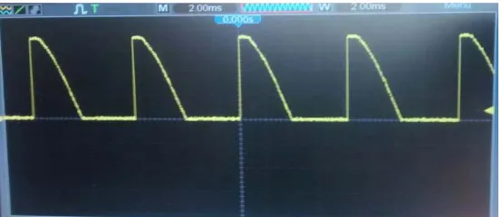
2) for firing angle, α=90°
[image:6.612.172.442.401.522.2]Fig. 8 Waveform of output voltage for firing angle, α=90°
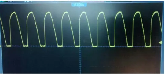
3) for firing angle, α=150°
The figure shows the waveform of output voltage of the bridge rectifier with resistive load. The value of average output voltage for this firing angle is given in table I.
[image:7.612.169.447.291.411.2]Fig. 9 Waveform of output voltage for firing angle, α=150°
TABLE I AVERAGE OUTPUT VOLTAGE VALUES OF BRIDGE RECTIFIER WITH RESISTIVE LOAD
CONTROL VOLTAGE FIRING ANGLE, OUTPUT VOLTAGE 0.82 V 30° 100.54 V
2.48 V 90° 54.11 V 4.1 V 150° 7.24 V
B. Bridge Rectifier Output for Inductive Load 1) for firing angle, α=30°
Fig. 10 Waveform of output voltage for firing angle, α=30°
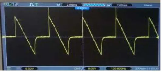
2) for firing angle, α=90°
[image:8.612.175.442.303.423.2]The figure shows the waveform of the output voltage of bridge rectifier with an inductive load. The value of average output voltage for this firing angle is given in table II.
Fig. 11 Waveform of output voltage for firing angle, α=90°
3) for firing angle, α=150°
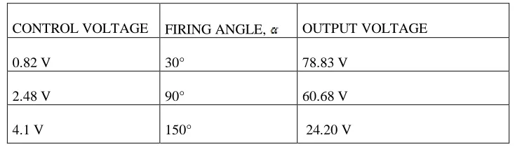
The figure shows the waveform of the output voltage of bridge rectifier with an inductive load. The value of average output voltage for this firing angle is given in table II.
[image:8.612.175.439.512.629.2]TABLE II AVERAGE OUTPUT VOLTAGE VALUES OF BRIDGE RECTIFIER WITH INDUCTIVE LOAD
CONTROL VOLTAGE FIRING ANGLE, OUTPUT VOLTAGE 0.82 V 30° 78.83 V
2.48 V 90° 60.68 V 4.1 V 150° 24.20 V
V. CONCLUSION
The strategy of digital control designed and implemented in this article for the firing control of SCRs in a single phase rectifier fulfilled the objectives proposed. The quantity of electronic elements used in the control of thyristors through the strategy presented notably decreased .
It observed the advantage of this strategy with respect to the traditional methods of control of thyristors, since the same result was obtained but of a manner more practical and cheaper , finally it obtained a control of phase angle from 0 to 180 grades with linear characteristics.
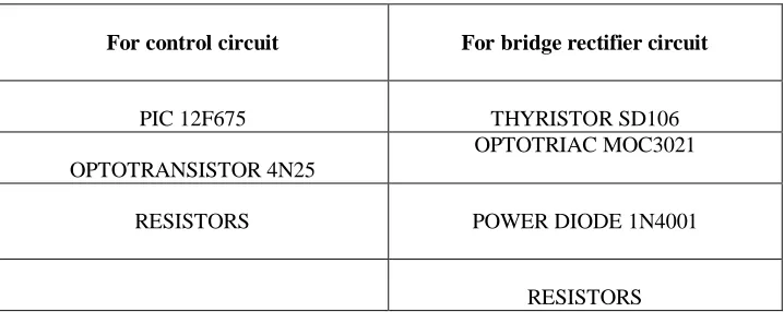
TABLE III LIST OF COMPONENTS USED
[image:10.612.171.444.302.514.2]
Fig. A1 Practical circuit of control and bridge rectifier.
For control circuit For bridge rectifier circuit
PIC 12F675 THYRISTOR SD106 OPTOTRANSISTOR 4N25
OPTOTRIAC MOC3021
RESISTORS POWER DIODE 1N4001
[1] P. S. Bimbhra, “Power Electronics,” Khanna Publishers, 3rd edition pp. 146-152, 2006.
[2] N. Mohan, T. M. Undeland and W. P. Robbins, “Power electronics: Converters, Applications and Design” New York: Wiley, 3rd edition, pp. 126-138, 2006. [3] R. Simard and V. Rajagopalan, “Economical equidistant pulse Firing scheme for Thyristorized D.C. drives,” IEEE Trans. Ind. Electron. Contr. Instrum., vol.
IECI-22, No.3, pp. 425-429, 1975.
[4] S.C.Gupta, K.Venkatesan, And K.Eape, “Generalized Firing Angle Controller Using Phase loop for Thyristor Control, ” IEEE Transactions On industrial Electronics and Control Instrumentation, vol. IECI-28, No. 1, February 1981.
[5] S. Murugesan and C.Kameswara, “Simple adaptative analog and digital trigger circuits for thyristors working under wide range of supply Frequency” IEEE Trans. Ind. Electron. Contr. Instrum., vol. IECI-24, No. 1, pp.46-49, 1977.
[6] Tirtharaj Sen, Pijush Kanti Bhattacharjee and Manjima Bhattacharya, “Design And Implementation Of Firing Circuit For Single- Phase Converter,” International Journal of Computer and Electrical Engineering, vol. 3, pp. 368-374, June 2011.
[7] Geno Peter, “Design Of Single Phase half Controlled Converter Using Cosine Wave Crossing Control With Various Protections,” International Journal of engineering Science and Technology, vol. 2(9),pp 4222-4227, 2010.
[8] Mukesh Gupta, Sachin Kumar, Vagicharla Karthik, “Design, Fabrication and Testing of cosine control Firing Scheme For Single Phase Half Controlled Bridge Rectifier,” International Journal of Advanced Research in Electrical, Electronics and Instrumentation Engineering, vol. 2, no.
8,pp.3834-3844,2013.
[9] L.H.Hoang, “A digitally controlled thyristor trigger circuit” Proc. IEEE, vol. 66, No.1, pp. 89-91, Jan. 1978.
[10] R. Arockiasamy and S. Doraipandy, “A novel trigger scheme for Thyristor operating under variable frequency anode supply,” IEEE Trans. Ind. Electron. Contr .Instrum., vol. IECI-22, No. 1, pp. 83-85, Feb.1975.
AUTHORS
First Author – Erney Fabian Castro Becerra, Pregrade student, Santander Paula Francisco University,[email protected]
Second Author –Diego Alejandro Parra Peñaranda, Pregrade student, Santander Paula Francisco University,
Third Author –Franklin Meer Garcia Acevedo,Pregrade Student , Santander Paula Francisco
University,[email protected]
Correspondence Author –