3G Mobile UMTS
Raghavendra J
1, Anji Reddy Y
2, Deepak Kumar R
2, Ravi T
31,2
Final Year B.Tech, Dept. of ECE, KL University, Vaddeswaram, AP, India
3
Associate Professor B.Tech, Dept. of ECE, KL University, Vaddeswaram, AP, India
Abstract- Rapid advancements in Information and
Communications Technology (ICT) have already had a profound impact on life in the 21st century. The growth of knowledge-based societies present great opportunities and challenges for the social and economic health of all countries. New telecommunications technologies such as UMTS will play a central role in the smooth transition to an Information Society by providing people with fast, unlimited access to information and services at anytime, from anywhere.
I. INTRODUCTION
MTS is the convergence of mobile communications, Information Technology (IT) and multimedia technologies. UMTS creates new opportunities for network operators, service providers and content providers to generate revenue and seize market share. The benefit of UMTS is richer, more powerful communication. UMTS is a suite of radio and network technologies that provide:
• better spectrum efficiency,
• high data transmission rates (up to 2 Mbit/s), • worldwide roaming capability,
•the capability to offer new multimedia applications and services, • interoperability with both fixed and mobile telecommunications services.
UMTS is the natural evolution from GSM and other second generation (2G)mobile systems.
It provides interconnection with 2G networks as well as other terrestrial nd satellite-based networks. UMTS presents a unique opportunity to cater to the needs of individuals in the Information Society. As a multi-national, multi-sector system that supports numerous protocols and transport technologies, UMTS eliminates barriers that oneposed problems for communications and enables the creation and delivery of fully personalized communication services to both mass market and corporate users.
II. UMTS STANDARD
UMTS is an International Mobile Telecommunications - 2000 (IMT-2000) 3G system.it is the 3rd generation Partnership Project is developing technical specifications or IMT-2000 and the International Telecommunication Union (ITU) framework for third-generation standards. 3GPP is a global co-operation between six organizational partners including European Telecommunications Standards Institute (ETSI), ho are recognized as being the world’s major standardization bodies. the 3G standardization environment. The other main IMT–2000
system proposed by the ITU is CDMA 2000. Operators ith existing IS-95 networks will migrate to CDMA 2000. CDMA 2000 will be deployed in North America and Asia. DMA 2000 is a narrowband system whereas UMTS, which uses WCDMA technology, s a wideband system. The first available release of CDMA 2000 does not provide transmission speeds recommended by the IMT-2000. However, the first UMTS release (3GPP Release 99) is on time and guarantees recommended peeds. CDMA 2000 will eventually deliver full IMT-2000 requirements. SM systems dominate the global market share of 2G systems. Western Europe, or example, exclusively uses the GSM standard. The UMTS standard will likely capture the majority of the 3G market share.
Significant market potential exists for UMTS. Recent trends indicate a rising demand
For Internet Protocol (IP) services which include access to: • the Internet,
• intranets and extranets, • mobility,
• multimedia services,
• speed (fast data transmission rates).
III. OVERVIEW OF UMTS RELEASE ARCHITECTURE
This section provides a general description of the current standard UMTS release architectures. UMTS architectures provide a smooth transition from second generation telecommunications systems by slowly phasing in new software and new network elements. 3GPP currently defines standards for the following UMTS releases
• 3GPP Release 99 (R99),
• 3GPP Release 4 (Next Generation Network NGN) architecture),
• 3GPP Release 5 (all-IP core network).
IV. 3GPP RELEASE 99 (R99)
3GPP Release 99 (R99) includes the following network elements:
• Radio Access Networks:
Base Station Subsystem (BSS) for access to GSM services which includes:
• Base Transceiver Stations (BTS), • Base Station Controller (BSC).
Universal Terrestrial Radio Access Network (UTRAN) for access to UMTS services and including:
• Node Bs,
• Radio Network Controller (RNC).
Core Network:
Circuit-Switched Core Network (CSCN) includes elements that support circuit switched connections. Circuit-switched connections are connections where the operator has full and exclusive use of the circuit until the connection is released. CSCN elements for R99 include:
Mobile services Switching Center (MSC), The MSC is the interface between the Radio Access Network (RAN) and fixed networks. It provides mobility management, call control and switching functions to enable circuit switched services to and from mobile stations.
Gateway Mobile services Switching Center (GMSC) The GMSC interfaces with the fixed networks, handles subscriber location information from the HLR and performs routing functions to and from mobile stations. GMSC functionality can be contained in all or some of the MSCs of the network, depending on network configuration.
InterWorking Function (IWF) The IWF provides interworking functionality between a Public Land Mobile Network (PLMN) and fixed networks (such as ISDN, PSTN and PDN). The IWF converts protocols used in the PLMN to those used in the corresponding fixed network.
Packet-Switched Core Network (PSCN) includes elements that support packet switching technology. Packet-switching technology routes packets of user data independently of one another. No dedicated circuit is established. Each packet can be sent along different circuits depending on the network resources available.
PSCN elements for R99 include: Serving GPRS Support Node (SGSN)
The SGSN and the GGSN are the interface elements between the RAN and fixed networks.
The SGSN provides mobilitiy management, session management and transfer and routing functions to enable the transfer of packet-switched data services.
Gateway GPRS Support Node (GGSN)
The GGSN handles subscriber location information and provides packet data transfer capabilities to and from mobile terminals.
Border Gateway (BG)
The BG provides connectivity, and interworking and roaming capabilities between two different PLMNs. Common Core Network elements are elements used by both the CSCN and PSCN. Common elements for R99 include:
Home Location Register (HLR)
The HLR is the permanent database for mobile subscriber information. The HLR is in charge of mobile subscriber management.
Visitor Location Register (VLR)
The VLR manages mobile subscribers in the home PLMN and those roaming in a foreign LMN. The VLR exchanges information with the HLR.
Authentication Center (AuC)
The AuC provides authentication and encryption functions for system security
Equipment Identity Register (EIR)
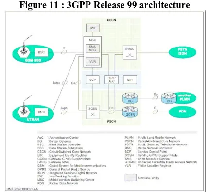
[image:2.612.337.551.369.567.2]The EIR stores information on mobile equipment identities. SMS MSCs. SMS MSCs enable the transfer of messages between the Short Message Service Center and the PLMN. See figure 11 for an illustration of 3GPP Release 99 network architecture. 5
Figure 11 : 3GPP Release 99 architecture
GPP Release 4 (R4)
3GPP Release 4 implements the NGN architecture in the core network, separating the control and user planes. This enables a true separation of control and connection operations, and provides the independence of applications and services from basic switching and transport technologies. 3GPP Release 4 (R4) introduces the following new network elements in addition to R99 elements:
Core Network: CSCN:
MSC server
also holds subscriber service data information and provides connection control for media channels in a CS-MGW.
GMSC server
The GMSC server provides call control and mobility management functions for a GMSC.
Circuit-Switched-Media GateWay (CS-MGW)
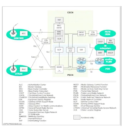
[image:3.612.338.550.70.290.2]The CS-MGW is an interface between the UTRAN and the Core Network. The CS-MGW supports both UMTS and GSM media. CS-MGW terminates bearer channels from circuit switched networks and media streams from packet networks. It supports media conversion, 6 bearer control and payload processing. See figure 12 for an illustration of 3GPP Release 4 network architecture.
Figure 12 : 3GPP Release 4 architecture
GPP Release 5 (R5)
3GPP Release 5 implements a unified IP backbone infrastructure which enables high performance services and functions. 3GPP Release 5 (R5) introduces the following new network elements in addition to R99 and R4 elements:
Core Network:
Common Core Network elements: • Home Subscriber Server (HSS)
• Internet protocol Multimedia (IM) subsystem.
The IM susbsystem consists of all Core Network elements that use the services provided by the PSCN to offer multimedia services. The IM susbsystem primarily includes the Call Server
Control Function (CSCF), Media Gateway
[image:3.612.64.274.242.451.2]Control Function (MGCF) and the Multimedia Resource Function (MRF).
Figure 13 : 3GPP Release 5 architecture
V. UMTS TECHNOLOGY
The main technological difference between 2G and 3G systems is the new multiple access technique in the Radio Access Network (RAN) that increases bandwidth and efficiency. This technology is called Code Division Multiple Access (CDMA). 3G standards organizations have selected three CDMA radio interface technologies for 3G networks:
• WCDMA which uses Frequency Duplex Division (FDD) mode, • TD-CDMA which uses Time Division Duplex (TDD) mode, • CDMA 2000 which is seen as the natural evolution for operators with existing IS-95 networks. This section describes: • the limitations of 2G systems,
• WCDMA,8
• Asynchronous Transfer Mode (ATM), • UMTS - Satellite mode (S-UMTS).
Limitations of 2G systems:
The limitations of 2G mobile systems such as GSM include: congestion, There are more than 300 million wireless subscribers worldwide and thus a need to increase system capacity.
• limited mobility around the world, • There is a need for global standardization. • limited services.
• There is a need for new multimedia applications and services.
Wideband - Code Division Multiple Access (WCDMA)
WCDMA optimally divides the available radio spectrum on the air interface into a number of channels and defines how these channels are allocated to the many users accessing the network. WCDMA allows for variable bit rates and variable Quality of Service (QoS).
• support for all types of services • enhanced privacy
A WCDMA system requires accurate power control to overcome the “near-far” problem. A signal close to the base station (Node B) with high power overwhelms the other signals from mobile phones that are farther away. The goal of power control in WCDMA is to have the signals from all of the User Equipments (UE) arrive at the base station with the same power level. If the transmitter is close to the receiver, less power is necessary. If the transmitter is farther away, more power is necessary. WCDMA systems use two types of power control:
Open-loop power control:
Open-loop power control is based on the sum of the power level of the UE and the power level of the Node B. The two power levels must remain a constant. In other words, if the UE receives a strong downlink signal from the Node B, then the UE will speak low. If the UE receives a weak signal downlink signal then the UE will speak loudly.
Closed-loop power control:
With closed-loop power control, power control bits are sent to the UE every 0.66 milliseconds to tell the mobile station to increase or decrease its transmission power. Closed loop power control is very fast. Because of Power Control, WCDMA phones have fewer power requirements which means they can handle smaller, lightweight, longer-life batteries. Rake receiver In UMTS, a Rake receiver is implemented in the UEs and base stations to provide:
• multi-service, • path diversity, • soft handover.
A Rake receiver can decode several signals simultaneously and combine them to improve the quality of the signal or to get several services at the same time. In radio communications, the 10 strength of a signal can decrease for many reasons. Natural obstacles such as buildings and hills cause reflections, diffractions and scattering. Consequently, multipath propagation occurs which means that the same radio signal arrives at the receiver through different reflected paths. The Rake receiver uses the inherent frequency diversity characteristics of WCDMA as a means of providing redundancy in the network. Because the signal is spread over a wide frequency band, it is transmitted and received simultaneously on two or more frequencies. The Rake
receiver identifies the different paths that the signal takes and combines them to improve the quality of the signal.
Soft Handover
Soft Handover means that the connection does not have to be broken in the original cell before connection in the successor cell. Soft Handover is possible with UMTS because WCDMA systems do not require the use of different frequencies in adjacent cells. Two mobile terminals use the same frequency band. A mobile terminal needs only one transmission chain to decode both simultaneously
.
Asynchronus transfer mode (ATM)
UMTS uses ATM in the Radio Access Network (RAN) for the reliable transfer of digital information. ATM has been chosen as the transport technology in UMTS Radio Access Networks because it supports a multi-service environment with variable bit rates and the ability to support variable QoS. ATM is also highly scalable which makes it excellent for interconnecting legacy systems and LANs and for building WANs on high-performance fiber-optic networks.
VI. SATELLITE UMTS (S-UMTS)
Satellite UMTS (S-UMTS) uses a single frequency band for communications between terrestrial and satellite networks. Satellite technology can readily provide global coverage and will play an 11 important role for UMTS in the future. The specifications for S-UMTS are ongoing. See figure 16 for an illustration of UMTS coverage.
REFERENCES
[1] DIGITAL TRANSMISSION SYSTEMS by David R Smith
[2] Telcordia GR-253-CORE, Synchronous Optical Network (SONET) Transport Systems: Common Generic Criteria (October 2009). Issue 5. [3] Horak, Ray (2007). Telecommunications and Data Communications
Handbook. Wiley-Interscience. p. 476. ISBN 978-0-470-04141-3. [4] ITU-T Rec. G.707/Y.1322, Network node interface for the synchronous
[5] ITU-T Rec. G.783, Characteristics of synchronous digital hierarchy (SDH) equipment functional blocks., Geneva: International Telecommunications Union, 2006-03, retrieved 2010-11-03
[6] ITU-T Rec. G.784, Management aspects of the synchronous digital hierarchy (SDH) transport network element., Geneva: International Telecommunications Union, 2008-03, retrieved 2010-11-03
[7] ITU-T Rec. G.803, Architecture of transport networks based on the synchronous digital hierarchy (SDH)., Geneva: International Telecommunications Union, March 2000, retrieved 2010-11-03
[8] “Synchronous Digital Hierarchy (SDH) Graphical Overview". Cisco. San Jose, California: Cisco Systems. 2006-10-01. Retrieved 2010-11-14. [9] Tozer, Edwin Paul J. (2004). "1.8.11 Synchronous Digital Hierarchy
(SDH)". Broadcast Engineer's Reference Book.
AUTHORS
First Author – Raghavendra [1]was born in 1991 in Andhra
pradesh. He is currently persuing B.Tech from K L University.
He is interested in electddyronics & communication and Networking., Email: [email protected]
Second Author – Anji Reddy[2]was born in 1990 in Andhra
Pradesh. He is pursuing his B.tech from K L University. He is interested in Communications and Wireless Networks., Email: [email protected]
Third Author – Deepak Kumar] was born in 1992 in Andhra
pradesh. He is currently pursuing B.Tech from K L University. He is interested in Wireless systems and Telecommunication. Email:[email protected]
Third Author – Thumati Ravi[3] is working as Associate
Proffesor in KL University. He is interested in Image Processing. Email: [email protected]
Correspondence Author – Raghavendra