International Journal of Emerging Technology and Advanced Engineering
Website: www.ijetae.com (ISSN 2250-2459,ISO 9001:2008 Certified Journal, Volume 5, Issue 1, January 2015)
59
An Analytical Solution to Stress State of Casing-Cement
Sheath-Formation System with the Consideration of its Initial
Loaded State and Wellbore Temperature Variation
Yucai Shi
1, Ben Li
2, Boyun Guo
3, Zhichuan Guan
4, Hui Li
51,4Professor & Qingdao, Shandong Prov., 266580, P. R. China
2,5
Ph.D Program & PO Box 44690 Lafayette, LA 70504, USA
3Professor& PO Box 44690 Lafayette, LA 70504, USA
Abstract-- Stress state analysis to casing-cement sheath-formation system (CCSFS) is the foundation of the wellbore integrity design and examination. Many elastic mechanic models have been established to calculate the stresses and displacements of CCFS, but all analytical models and most finite element models took no account of the initial loaded state, and ignored the initial stresses and displacements on cement sheath and formation, and regarded the given outer casing diameter and the measured wellbore diameter as the initial inner and outer diameters of cement sheath respectively. Now, a few finite element models have taken the initial stress of cement sheath into account, but ignored the initial strains of cement sheath and formation. To accurately solve the stresses of CCSFS and better direct the wellbore integrity design and examination, a new analytical model to solve the stresses of CCSFS with vertical wellbore and isotropic horizontal in-situ stress has been derived according to elastic mechanic theory, which can take the initial loaded state and temperature variation into account. Combining with an instance analysis, the stress distribution rules influenced by its initial loaded state and inner casing pressure have been discussed. Research showed that whether considering the initial loaded state can cause significant differences on the stress values and their variation trends of CCSFS. Especially, the tangential stress in casing unit and the radial stress in cement sheath have the maximum differences. Taking the initial loaded state into account is fully necessary and conducive to wellbore integrity design and examination.
Keywords-- wellbore integrity; cement sheath; initial loaded state; stress; analytical model
I. INTRODUCTION
In the whole life of an oil and gas well, avoiding damages in casing, cement sheath and formation, keeping the integrity of casing-cement sheath-formation system (CCSFS) have great significances to maintain regular production and extend the service life. Solving the stresses and displacements of CCSFS is the basis to wellbore integrity design and examination. Many analysis models have been established to calculate the stresses and displacements of CCFS.
International Journal of Emerging Technology and Advanced Engineering
Website: www.ijetae.com (ISSN 2250-2459,ISO 9001:2008 Certified Journal, Volume 5, Issue 1, January 2015)
60
The stress distribution rules influenced by its initial loaded state have been discussed. way to do this is simply to download the template, and replace(copy-paste) the content with your own material.II. BASIC MODEL OF CCSFS
As shown in Figure 1, the CCSFS is equivalent to an assembling cylinder with three kinds of material. The inner unit is casing (Young's modulus & Poisson’s ratio is & respectively), the middle unit is cement sheath (Young's modulus & Poisson’s ratio is & respectively), and the outer unit is formation (Young's modulus & Poisson’s ratio is & respectively).
The external loads on the assembling cylinder are regarded as known parameters, including the inner casing pressure and the outer isotropic horizontal in-situ stress. In the whole service life of an oil &gas well, the inner casing pressure is different during well completion, testing and production, but the horizontal in-situ stress is regarded unchanged in most cases. Except external loads above, the thermal stress due to wellbore temperature variation is taken into account.
However, considering that the CCSFS always undergoes downhole temperature and pressure variations, there is no initial state without any external loads. That is to say, the inner and outer radii of cement sheath are always unknown parameters during well completion, testing and production.
According to elastic mechanic theory, solving the stresses of CCSFS with vertical wellbore and isotropic horizontal in-situ stress is an axisymmetric plane strain problem. This document is template. We ask that authors follow some simple guidelines. In essence, we ask you to make your paper look exactly like this document. The easiest way to do this is simply to download the template, and replace (copy-paste) the content with your own material.
III. SOLUTIONS OF KEY PARAMETERS
Three basic states with or without external loads are discussed here, which are named as initial loaded state, reloaded state and virtual complete unloaded state.
To solve the problem, usually adopt the following basic assumptions [1-4].
1)The CCSFS is always in elastic deformation state. Thus, the plastic deformation can be ignored, and elastic mechanics theory can be used.
2)Cement sheath cements well and contacts continuously with casing and formation. That is to say, under the action of external loads, inner and outer cement sheath radii are always equal to outer casing radius and wellbore radius, respectively; the radial stresses on inner and outer cement sheath walls are equal to those on outer casing wall and wellbore wall, respectively.
Figure.1 Casing-Cement Sheath-Formation System
3.1 Initial loaded state
Here, the initial loaded state refers to a loaded state after cementing operation that slurry has completely solidified under the given downhole temperatures and pressures, and mechanical parameters of cement sheath have turned into stable values.
Obviously, initial loaded state has initial stresses and displacements anywhere. The known key parameters only include the inner casing pressure Pmi(drilling fluid pressure in casing) and the isotropic horizontal in-situ stress σh . The unknown key parameters include inner cement sheath radius rcai (outer casing radius), outer cement sheath radius
rcbi (wellbore radius), as well as the initial radial stresses
Pcai on inner cement sheath wall (outer casing wall) and
Pcbi on outer cement sheath wall(wellbore wall).
3.2 Virtual complete unloaded state
International Journal of Emerging Technology and Advanced Engineering
Website: www.ijetae.com (ISSN 2250-2459,ISO 9001:2008 Certified Journal, Volume 5, Issue 1, January 2015)
[image:3.612.326.560.325.494.2]61
Figure 2 Completed Unloaded StateConsidering that the mechanical parameters of casing, cement sheath and formation are different, it can be inferred that under complete unloaded state, the inner cement sheath radius is likely not equal to the outer casing radius, and the outer cement sheath radius is not likely equal to the wellbore radius. However, all analytical models and most finite element models have taken no account of the influence of the initial loaded state, and ignored the initial stresses and displacements, and regarded the given outer casing diameter and wellbore diameter as the initial inner and outer diameters of cement sheath under unloaded state respectively. Obviously, it is inconsistent with the fact that CCSFS always undergoes the downhole temperature and pressures, and inevitably has initial stresses and displacements.
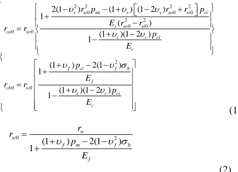
Under complete unloaded state, the known key parameters only include inner casing radius rsi0and outer casing radius rso0. The unknown key parameters include inner cement sheath radius rca0 and outer cement sheath radius rcb0, wellbore radius rw0. Due to the outer formation radius rfis always far greater than the wellbore radius rw0, it can be regarded as known parameter. How to solve the unknown parameters depends on the initial loaded state. That is to say, either the initial stresses or displacements of cement sheath must be known in advance.
However, all initial stresses and displacements cannot be measured directly and accurately until now. Three methods have been presented to estimate the initial radial stresses on cementing faces. All the methods assume that the initial radial stresses on two cementing faces reach to the same value, but different method provides different values. The first assumes that the initial radial stresses are equal to the annulus fluid pressure when cement solidifying. The second assumes that the initial radial stresses are equal to the annulus fluid pressure while solidifying minus the formation pore pressure. The third assumes that the initial radial stresses are equal to zero. For unexpansive cement slurry, the first gives the upper limit value; the third gives the lower limit value; the second gives a medium value and is commonly used.
Assuming that there is no temperature change when the initial loaded state turns into the complete unloaded state, set the initial radial stresses on cementing faces equal to the same value Pciand regard it as known parameter. The inner cement sheath radius rca0 and the outer cement sheath radius rcb0 under complete unloaded state are inversely calculated according to the formula of thick wall cylinder displacement.
Usually, wellbore diameter is measured in open hole state before running casing. When measuring wellbore diameter, set the drilling fluid pressure on wellbore wall as
Pm and the isotropic horizontal in-situ stress as σh, the measured wellbore radius as rw. The wellbore radius rw0 under complete unloaded state is inversely calculated according to the formula of thick wall cylinder displacement.
2 2 2 2
0 0 0
2 2
0 0
0 0
2
0 0
2(1 ) (1 ) (1 2 )
1
( )
(1 )(1 2 )
1
(1 ) 2(1 )
1
(1 )(1 2 )
1
s si mi s s so si ci
s so si ca so
c c ci
c
f ci f h
f cb w
c c ci
c
r p r r p
E r r
r r
p E
p
E
r r
p E
(1)
0 2
(1 ) 2(1 )
1
w w
f m f h
f
r r
p
E
(2)
3.3 Reloaded state
Here, the reloaded state refers to a loaded state after cementing and in the process of well testing and regular production that bears inner casing pressure on inner casing wall and horizontal in-situ stress on outer boundary of formation, and thermal stress due to temperature variation.
International Journal of Emerging Technology and Advanced Engineering
Website: www.ijetae.com (ISSN 2250-2459,ISO 9001:2008 Certified Journal, Volume 5, Issue 1, January 2015)
62
In addition, consider the influence of thermal stress due to temperature variation, and set the thermal expansive coefficient of casing unit, cement sheath unit and formation unit is αs, αc and αfrespectively. Under initial loaded state, set the initial temperature of each unit equal to the same value Ti. Under reloaded state, set the average temperature of casing unit, cement sheath unit and formation unit as Ti,Tc and Tf respectively.
After solving the key geometric parameters under complete unloaded state, to calculate the radial stress Pca on inner cement sheath wall and Pcb on outer cement sheath wall is the key to solve the stress distributions of CCSFS.
According to the formula of thick wall cylinder displacement and the continuous contact assumption on cementing faces, a dual equations at a ti me is derived at last, in which the unknown parameters Pca and Pcb are the radial stresses on cementing faces.
11 12 1 10
21 22 2 20
ca cb i
ca cb h
c p c p b p b
c p c p b b
(3) Where,
2 2 2 2
0 0 0 0 0 0
11 2 2 2 2
0 0 0 0
2 2 0 0
12 2 2
0 0
2 2 0 0
21 2 2
0 0
2 0 22
(1 )[(1 2 ) ] (1 )[(1 2 ) ]
( )
2 (1 )
( )
2 (1 )
( )
(1 )[(1 2 )
s s so si so s c c ca cb ca
so si c cb ca
s c cb ca c cb ca f c ca cb
c cb ca
f c c cb ca
r r r E r r r
c
r r E r r
E r r
c
E r r
E r r
c
E r r
E r r
c
2 0 0 0 2 2 0 0 2 2 0 01 2 2
0 0
2 2
10 0 0 0 0
20 0 0 0 0
]
(1 )
( )
2(1 )
2(1 )
( ) (1 ) ( ) (1 ) ( )
( ) (1 ) ( ) (1 ) ( )
cb
f w c cb ca
s si so so si
f wo
s ca so c c c i ca s s s i so
f w cb f f f i w c c c i cb
r
r
E r r
r r b
r r
b r
b E r r T T r T T r
b E r r T T r T T r
(4) According to Eq.(3) and Eq.(4), the radial stresses on cementing faces are solved.
22 1 10 12 2 20
11 22 21 12
11 2 20 21 1 10
11 22 21 12
( ) ( ) ( ) ( ) i h ca h i cb
c b p b c b b
p
c c c c
c b b c b p b
p
c c c c
(5)
After the radial stresses on cementing faces are solved, the stresses and displacement at anywhere can be calculated according to the formula of the stress and displacement of thick wall cylinder.
IV. COMPUTATIONAL ANALYSIS OF AREAL EXAMPLE
To verify and emphasize the importance and necessity to take the initial loaded state into account, wellbore temperature variation is ignored here.
A typical analytical model [6,7] without the consideration of initial loaded state, a typical finite element model[16] with the consideration of initial stress have been selected and compared to the new analytical model.
4.1 Given Computational Conditions
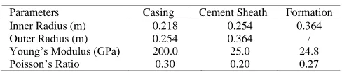
This living example is selected from an existing literature [16]. All geometrical parameters and mechanic parameters are shown in Table 1. In addition, the formation pore pressure is 20.0MPa; the isotropic horizontal in-situ stress is 40.0MPa; the normal drilling fluid pressure while drilling is 22.0MPa; the annulus fluid pressure while cement solidifying is 30.0MPa.
Table 1
Basic Parameters of a Real Example
Parameters Casing Cement Sheath Formation
Inner Radius (m) 0.218 0.254 0.364
Outer Radius (m) 0.254 0.364 /
Young’s Modulus (GPa) 200.0 25.0 24.8
Poisson’s Ratio 0.30 0.20 0.27
4.2 Compare to the Existing Models
Set the initial radial stresses on cementing faces equal to 10.0MPa and equal to that of the existing literature. Set the inner casing pressure as 40.0MPa, calculate the stresses on cementing faces by the new analytical model and the existing analytical model. Then extract the computational results from the existing finite element model.
A whole contrastive analysis is presented in Figure 3 and Figure 4. It is shown that:
[image:4.612.322.566.417.469.2]International Journal of Emerging Technology and Advanced Engineering
Website: www.ijetae.com (ISSN 2250-2459,ISO 9001:2008 Certified Journal, Volume 5, Issue 1, January 2015)
63
2) The values and variation trends of the radial andtangential stresses solved by the new analytical model have obvious differences from those of the existing typical finite element model which considers the initial stresses and ignores the initial displacements. In general, the radial and tangential stresses solved by these two models have the maximum differences in casing unit; the radial stresses are quite close and the tangential stresses are close in cement sheath unit and formation unit. The contrastive analysis has shown that when solving the stresses and displacements of CCSFS, it is fully necessary to take the influence of the initial loaded state into account. If not, the computational results may departure from actual values severely.
4.3 Analysis of the Influence Due to Initial Loaded State.
Set inner casing pressure equal to 40.0MPa, select the initial radial stresses on cementing faces equal to 5.0MPa, 10.0MPa, 20.0MPa respectively, solve the stresses of CCSFS under different initial radial stresses by the new analytical model.
A whole contrastive analysis is presented in Figure 5 and Figure 6. Under the same inner casing pressure, it is shown that:
1)The radial stress (compressive stress) at anywhere increase while increasing the initial radial stresses on cementing faces.
2)When increasing the initial radial stresses on cementing faces, the tangential stress (not always compressive stresses) have different variation trends in different units. The absolute value of tangential stress (tensile stress) in casing unit decrease; the tangential stress (compressive stress) in cement sheath unit increase, and the tangential stress (compressive stress) in formation unit decrease. 3)The radial stress in cement sheath unit and the tangential
[image:5.612.338.546.147.465.2]stress in casing unit bear the maximum influence due to the initial radial stress.
Figure.3 Comparison of Radial Stress
0.10 0.15 0.20 0.25 0.30 0.35 0.40 0.45 0.50 -150
-125 -100 -75 -50 -25 0 25 50
Analytical model[6,7]
New analytical model Finite element model[16]
T
a
n
g
e
n
ti
a
l
st
re
ss
σθ
(MPa
)
Distance from wellbore centre(m)
Figure.4 Comparison of Tangential Stress
0.10 0.15 0.20 0.25 0.30 0.35 0.40 0.45 0.50 0
5 10 15 20 25 30 35 40
pci=5MPa
pci=10MPa
pci=20MPa
R
a
d
ia
l
st
re
ss(
M
P
a
)
[image:5.612.342.546.491.622.2]Distance from wellbore centre(m)
Figure.5 Influence on Radial Stress due to Initial Loaded State
0.10 0.15 0.20 0.25 0.30 0.35 0.40 0.45 0.50
-200 -150 -100 -50 0 50
p
ci=5MPa
p
ci=10MPa
p
ci=20MPa
Ta
n
g
e
n
ti
a
l
st
re
ss(
M
P
a
)
Distance from wellbore centre(m)
Figure.6 Influence on Tangential Stress due to Initial Loaded State
4.4 Analysis of the Influence Due to Inner Casing Pressure.
[image:5.612.55.277.515.700.2]International Journal of Emerging Technology and Advanced Engineering
Website: www.ijetae.com (ISSN 2250-2459,ISO 9001:2008 Certified Journal, Volume 5, Issue 1, January 2015)
64
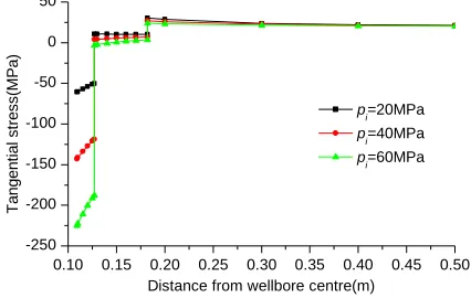
A whole contrastive analysis is presented in Figure 7 and Figure 8. Under the same initial radial stress, it is shown that:1)When increasing inner casing pressure, the radial stress (compressive stress) at anywhere increase, and the tangential stress (not always compressive stress) decrease. If the tangential stress in casing unit are tensile stress, their absolute values increase.
2)The stresses in casing unit bear the maximum influence due to the inner casing pressure; the stress in formation unit bear the minimum influence due to the inner casing pressure.
0.10 0.15 0.20 0.25 0.30 0.35 0.40 0.45 0.50
0 10 20 30 40 50 60
pi=20MPa
pi=40MPa
p
i=60MPa
R
a
d
ia
l
st
re
ss(
M
P
a
)
Distance from wellbore centre(m)
Figure.7 Influence on Radial Stress due to Inner Casing Pressure
0.10 0.15 0.20 0.25 0.30 0.35 0.40 0.45 0.50
-250 -200 -150 -100 -50 0 50
p i=20MPa p
i=40MPa p
i=60MPa
Ta
n
g
e
n
ti
a
l
st
re
ss(
M
P
a
)
[image:6.612.64.269.263.415.2]Distance from wellbore centre(m)
Figure.8 Influence on Tangential Stress due to Inner Casing Pressure
V. CONCLUSIONS AND SUGGESTIONS
Based on theoretical derivation and contrastive analysis of a living example, some conclusions have drawn as follows.
1)Casing-cement sheath-formation system has initial loaded state with initial stresses and initial displacements. If the system is unloaded completely, the inner and outer radii of cement sheath are not equal to the given outer casing radius and wellbore radius respectively.
2)According to elastic mechanic theory, a new analytical model to solve the stresses of casing-cement sheath-formation system with isotropic horizontal in-situ stress is derived, which has taken the initial loaded state (including initial stresses and displacements) and wellbore temperature variation into account.
3)Contrastive analysis with living example is shown that whether considering the influence of initial state may cause magnificent differences to the values and variation trends of stresses of the system. Taking the initial state into account is fully necessary.
4)When increasing the initial radial stresses on cementing faces, the radial stresses(compressive stresses) at anywhere increase; the tangential stresses(not always compressive stresses) have different variation trends in different units; the radial stress in cement sheath unit and the tangential stress in casing unit bear the maximum influence due to the initial radial stresses..
5)When increasing the inner casing pressure, the radial stresses(compressive stresses) at anywhere increase; the tangential stresses(not always compressive stresses) decrease; the stresses in casing unit bear the maximum influence due to the inner casing pressure; the stresses in formation unit bear the minimum influence due to the inner casing pressure.
6)Until now, because the initial radial stresses on cementing faces cannot be obtained easily and accurately, it is necessary to continue to explore the initial state of cement sheath and estimate the initial stresses on cementing faces reasonably.
Funding
1)China National Key Basic Research Development Plan (973 Plan- 2010CB226706), China Department of Science & Technology (DST);
2)China National High Technology Research and Development Program (863 Program- 2012AA091501), China Department of Science & Technology (DST); 3)United States Department of Energy’s National Energy
[image:6.612.61.274.460.595.2]International Journal of Emerging Technology and Advanced Engineering
Website: www.ijetae.com (ISSN 2250-2459,ISO 9001:2008 Certified Journal, Volume 5, Issue 1, January 2015)
65
REFERENCES[1] Fang, J., Zhao H.W., and Yue B.Q, 1995, “Analysis of Loading Property of Casing and Cement Sheath Under Non-uniform Geologic Stress,” Journal of University of Petroleum, 19(6), pp. 52-57.
[2] Fang J., Yue B.Q. and Zhao H.W, 1997, “Analysis of surface loading of casing and cement sheath under non-uniform geologic stress,” Journal of University of Petroleum, 21(1), pp.46-48. [3] Li J., Chen M., and Liu G.H. , 2005, “Elastic-plastic analysis of
casing-concrete sheath-rock combination,” Acta Petrolei Sinica, , 26(6), pp. 99-103.
[4] Li J., Chen M., and Zhang H., 2005, “Effects of cement sheath elastic modulus on casing external collapse load,” Journal of University of Petroleum, 2005, 29(6), pp. 41-44.
[5] Yin Y.Q., Cai Y.G., and Chen Z.W., 2006, “Heoretical solution of casing loading in non-uniform ground stress field,” Acta Petrolei Sinica, 27(4), pp. 133-138.
[6] Yin Y.Q., Chen Z.W., and Li P.G. 2006, “Theoretical solutions of stress distribution in casing-cement and stratum system,” Chinese Journal of Theoretical and Applied Mechanic, 38(6), pp. 835-842. [7] Chen Z.W., Yin Y.Q., 2007, “Theoretical study on effect of cement
sheath on casing load,” Acta Petrolei Sinica, 28(3), pp. 141-144. [8] Chen Z.W., Cai Y.G., 2009 “Study on casing load in a
casing-stratum system by elastoplastic theory,” Petroleum Exploration and Development, 36(2), pp. 242-246.
[9] Yang Z.F., Meng Q.Y., and Chen X.L., 2012, “ The theoretical radial stress solution and its experimental verification of expansion cement at annulus interfaces, ”Petroleum Exploration and Development , 39(5), PP. 605-611.
[10] Haider, M. G, S.J, 2012 “Modeling of a Well-bore Composite Cylinder System for Cement Sheath Stress Analysis in Geological Sequestration of CO2,” ARMA 12-369, 46th US Rock Mechanics / Geomechanics Symposium, Chicago, IL, USA 2012.
[11] Li Y., Liu S.Q., and Wang Z.H. 2010 “Analysis of cement sheath coupling effects of temperature and pressure in non-uniform in-situ stress field,” SPE 131878, CPS/SPE International Oil & Gas Conference and Exhibition in China, Beijing, China, 8-10 June 2010. [12] Li Y., Yuan J.P., and Qi F.Z., 2012 “Analysis of Cemented Casing Mechanical Failure under Arbitrary in-situ Stress Field Coupling Effects of Downhole Pressure and Temperature,” IADC/SPE 155895, IADC/SPE Asia Pacific Drilling Technology Conference and Exhibition, Tianjin, China, 9-11 July 2012.
[13] A. Nabipour, B. Joodi, and M. Sarmadivaleh, 2010, “Finite Element Simulation of Downhole Stresses in Deep Gas Wells Cements. Paper SPE 132156, SPE Deep Gas Conference and Exhibition, Manama, Bahrain, 24-26 January 2010.
[14] Yuan Z.G., Abdullah S.Al-Yami, and Jerome Schubert, 2012 “Cement Failure Probability under HPHT Conditions Supported by Long Term Lab Studies and Field Cases,” SPE 154746, SPE Annual Technical Conference and Exhibition, San Antonio, Texas, USA, 8-10 October 2012.
[15] Shen Z., F.E.Beck, 2012 “Three-Dimensional Modeling of Casing and Cement Sheath Behavior in Layered, Nonhomogeneous Formations,” IADC/SPE 156469, IADC/SPE Asia Pacific Drilling Technology Conference and Exhibition, Tianjin, China, 9-11 July 2012.
[16] Runar Nygaard, Saeed Salehi, and Benjamin Weideman, 2014 “Effect of Dynamic Loading on Wellbore Leakage for the Wabamun Area CO2-Suquestration Project,” SPE 146640, Journal of Canadian Petroleum Technology, January 2014, pp. 69-82.
[17] K.E. Gray, E. Podnos, and E. Becker, 2009 “Finite-Element Studies of Near-Wellbore Region During Cementing Operations:Part I,”. SPE 106998, SPE Drilling & Completion, March 2009, pp. 127-136. [18] A. Garnier, J. Saint-Marc, and A.-P. Bois, 2008 “A Singular Methodology to Design Cement Sheath Integrity Exposed to Steam Stimulation,” SPE/PS/CHOA 117709, 2008 SPE International Thermal Operations and Heavy Oil Symposium, Calgary, Alberta, Canada, 20-23 October 2008.
[19] Jérémie Saint-Marc, André Garnier, and Axel-Pierre Bois, 2008 “Initial State of Stress: The Key to Achieving Long-Term Cement-Sheath Integrity,” SPE 116651, 2008 SPE Annual Technical Conference and Exhibition, Denver, Colorado, USA, 21-24 September 2008.
[20] A.-P. Bois, A. Garnier, and F. Rodot, 2009 “How to Prevent Loss of Zonal Isolation Through a Comprehensive Analysis of Micro-Annulus Formation,” SPE 124719, 2009 SPE Annual Technical Conference and Exhibition, New Orleans, Louisiana, USA, 4-7 October 2009.
[21] D. Fourmaintraux, A.-P. Bois, and C. Franco, 2005 “Efficient Wellbore Cement Sheath Design Using the SRC (System Response Curve) Method,” SPE 94176, SPE Europec/EAGE Annual Conference, Madrid, Spain, 13-16 June 2005.
[22] A-P. Bois, A. Garnier, and G. Galdiolo, 2010 “Use of a Mechanistic Model to Forecast Cement-Sheath Integrity for CO2 Storage,” SPE 139668, SPE International Conference on CO2 Capture, Storage, and Utilization, New Orleans, Louisiana, USA, 10-12 November 2010.