International Journal of Emerging Technology and Advanced Engineering
Website: www.ijetae.com (ISSN 2250-2459,ISO 9001:2008 Certified Journal, Volume 3, Issue 9, September 2013)
655
Load Frequency Control Using Fuzzy PI Controller Generation
of Interconnected Hydro Power System
Ramanand Kashyap
1, Prof. S.S. Sankeswari
2, Prof. B. A. Patil
31HOD Electrical Engg. Dept., MGM’s Polytechnic, Aurangabad, Maharashtra, India.
2HOD.Elect.Engg.Dept, College of Engg. Ambajogai, Dr.B.A.M.U. Aurangabad, Maharashtra, India. 3 Principal, MGM’s Polytechnic, Aurangabad, Maharashtra, India.
Abstract- Now a days the issue on Load frequency control
in interconnected power system different area how maintain. The main objective of Automatic Generation Control (AGC) is to balance the total system generation against system load losses so that the desired frequency and power interchange with neighboring systems is maintained. Any mismatch between generation and demand causes the system frequency to deviate from its nominal value. Thus high frequency deviation may lead to system collapse. This necessitates a very fast and accurate controller to maintain the nominal system frequency. This paper deals with load frequency control of an interconnected two area hydro-hydro system. The system is incorporated with conventional proportional-integral (PI) and fuzzy logic controller (FLC). We are assuming that all areas in a system operate at the same frequency because the traditional approach for interconnection turned out to be unsuccessful for hydro-hydro systems. Time domain simulation is used to study the performance, when a 0.5% step load disturbance is given in area of the system. Finally the simulation results of conventional PI controller is compared with fuzzy logic PI controller and proved that FLC yields better control performance.
Keywords--LFC power system , conventional controller
fuzzy controller &ss Simulation result
I. INTRODUCTION
Load-frequency control (LFC) issue in power systems has a long history and its literature is huge. The preliminary LFC schemes have evolved over the past decades, and interest continues in proposing new intelligent LFC approaches with an improved ability to maintain tie-line power flow and system frequency close to specie values. In case of a hydro power, the power system frequency regulation can be affected due to water flow fluctuation. This leads to imbalance between power generation and power demand, and as a result, frequency will deviate from its nominal value. Significant frequency deviations may cause under/over frequency relay operations and finale disconnect some parts of system loads and generations[1]. The impact of hydro power generation on system frequency response and LFC mechanism.
The conventional LFC designs are usually suitable for working at specific operating points, and they are not more efficient for modern power systems, considering increasing size, changing structure, emerging renewable energy sources, and new uncertainties. Most of conventional LFC creation methodologies provide model-based controllers that are difficult to use for large-scale power systems with nonlinearities, and uncertain parameters[6]. Over the years, several Conventional control techniques are used for the frequency regulation / LFC issue in the power systems; however, there are just few reports on the intelligent frequency control design in the presence of hydro power units.
Recently, fuzzy logic because of simplicity, robustness, and reliability is used in almost all fields of science and technology, including solving a wide range of control problems in power system control and operation. The fuzzy control methodology tries to establish the controller directly based on the measurements, long-term experiences, and the knowledge of domain experts/operators. This paper presents the performance of two area interconnected hydro-hydro system with conventional PI and fuzzy logic controller [10]. The conventional PI control strategy does not give adequate control performance when a 0.5% step load disturbance is given in area of the system. Therefore an optimum fuzzy logic controller has been proposed in this paper. The difficulty in obtaining the optimum settling time of previously said controller is mitigated by using FLC. Simulation results confirm that the fuzzy logic controller greatly reduces the overshoots. The settling time is also reduced considerably.
II. LOAD FREQUENCY CONTROL
International Journal of Emerging Technology and Advanced Engineering
Website: www.ijetae.com (ISSN 2250-2459,ISO 9001:2008 Certified Journal, Volume 3, Issue 9, September 2013)
656 Load frequency control, as the name signifies, regulates the power flow between different areas while holding the frequency constant.
As we have in following example that the system
frequency rises when the load decreases if ΔPref is kept at
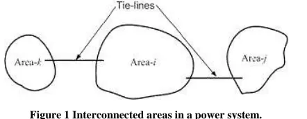
zero. Similarly the frequency may drop if the load increases. However it is desirable to maintain the frequency constant such that Δf=0 . The power flow through different tie-lines are scheduled - for example, area- i may export a pre-specified amount of power to area- j while importing another pre-specified amount of power from area- k . However it is expected that to fulfill this obligation, i absorbs its own load change, i.e., increase generation to supply extra load in the area or decrease generation when the load demand in the area has reduced. While doing this
area- i must however maintain its obligation to
[image:2.612.63.284.361.447.2]areas j and k as far as importing and exporting power is concerned. A conceptual diagram of the interconnected areas is shown in Figure 1.
Figure 1 Interconnected areas in a power system.
We can therefore state that the load frequency control (LFC) has the following two objectives:
Hold the frequency constant ( Δf = 0) against any load
change. Each area must contribute to absorb any load change such that frequency does not deviate.
Each area must maintain the tie-line power flow to its
pre-specified value. The first step in the LFC is to form the area control error (ACE) that is defined as
where Pt
ie and Psc
h are tie-line power and scheduled power through tie-line
respectively and the constant Bf is called the frequency bias
constant [1,2].
The change in the reference of the power setting ΔPref,
i , of the area- i is then obtained by the feedback of the ACE
through an integral controller of the form
(2)
Where Ki is the integral gain. The ACE is negative if the
net power flow out of an area is low or if the frequency has dropped or both. In this case the generation must be
increased. This can be achieved by increasing ΔPref, i . This
negative sign accounts for this inverse relation
between ΔPref, i and ACE. The tie-line power flow and
frequency of each area are monitored in its control center.
Once the ACE is computed and ΔPref, i is obtained from (1),
commands are given to various turbine-generator controls to adjust their reference power settings.
III. POWER SYSTEM
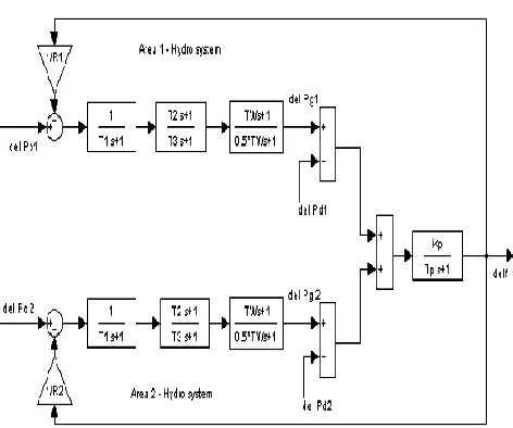
A block diagrams of two area interconnected power systems for the uncontrolled & nonlinearities is shown in figure 2.[2,10] In the diagrams, the frequency (system frequency common to all areas) is determined by integrating the net system accelerating/decelerating power (i.e. difference of total system generation and load). Since the difference between the area frequencies is neglected, the traditional approach cannot be used to compute the tie line flow deviations. In order to obtain the tie line flows the area power balance equations has been used. The power balance equation for the ith area is written as
(3)
Where Ptie is the tie line power flow, Pgi is the area generation of i th area, Pdi is the ith area load disturbance, Hi is the inertia constant of ith area and f is the system frequency [1,8]The Purpose of all AGC is the frequency used for one area to compute ACE should be the same as used in the other areas so long as they remain interconnected”.
International Journal of Emerging Technology and Advanced Engineering
Website: www.ijetae.com (ISSN 2250-2459,ISO 9001:2008 Certified Journal, Volume 3, Issue 9, September 2013)
[image:3.612.326.559.108.286.2]657
Figure 2 Transfer model of Interconnected areas in a power system.
IV. CONTROL METHODOLOGY
4.1 Open Loop
The nominal parameters of the system are given in Appendix. Matlab version 2009a has been used to obtain dynamic response such as Δf and ΔPtie, for 0.05% step load perturbation in area 2 of the system. Fig. 3(a)-(b) shows the open loop responses of the hydro-hydro system. Reference [2] clearly states that tie line power exchange should be / 2 del P . Here, tie line power deviation is 0.005 pu MW as shown in Fig. 3(b). Hence Eq. (3) is justified.
Figure 3(a) Open loop Del F.
Figure 3(b) Open loop Del Tie line
4.2 PI Controller
One the most widely used control for using the power systems . Proportional controller is used get to the steady state condition much quicker.The controller produce a control signal proportional to the error in the system. Integrator tends to increase control action, thus driving the plant out put towards the demand output[10]. The control signal can be written as,
(4)
(5)
Where Kp and Ki are proportional and integral controller gain respectively. To find the optimum value of the conventional Kp and Ki, integral square error (ISE) criterion has been used. For ISE technique the objective function used is, [1]
(6)
[image:3.612.53.289.134.331.2] [image:3.612.65.277.489.635.2]International Journal of Emerging Technology and Advanced Engineering
Website: www.ijetae.com (ISSN 2250-2459,ISO 9001:2008 Certified Journal, Volume 3, Issue 9, September 2013)
658 4.3 Fuzzy controller
Fuzzy logic is a problem solving control technique in control system engineering. The concept of fuzzy logic was
developed by Zadeh in 1965[9]. The 1st fuzzy controller
developed by Mamdani and Pappis in 1977, was steam engine controller and later fuzzy traffic lights. The FLCS design can be normally divided in to three areas namely allocation of area of inputs, determination of rules and defuzzifying of outputs into a real value[7]. In this study the proposed fuzzy controller takes the input as ACE and ACĖ, which is given in (1).
[image:4.612.331.557.321.644.2]The block diagram of fuzzy logic controller is shown in Figure 4 [4]. Membership Functions (MF) specifies the degree to which a given input belongs to set. Here, seven membership function have been used to explore best settling time namely, Negative Big (NB), Negative Medium (NM), Negative Small (NS), Zero (ZO), Positive Small (PS), Positive Medium (PM) and Positive Big (PB).
Fig. 4 Fuzzy Logic Controller
Fuzzy rules are conditional statement that specifies the relationship among fuzzy variables. These rules help us to describe the control action in quantitative terms and have been obtained by examining the output response to corresponding inputs to the fuzzy controller. Rules are given in Table I. The rules are interpreted as follows,
If ACE is NB and ACĖ is NS then output is PM
V. SIMULATION AND RESULTS
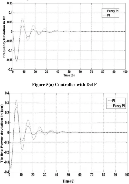
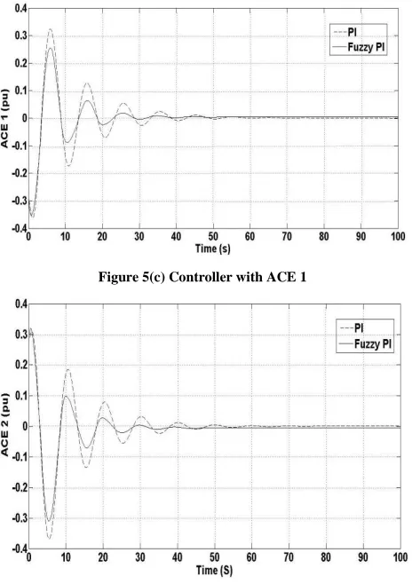
Performed simulations using PI and fuzzy controllers applied to a two area interconnected power systems. The developed system is simulated with 0.5% step load disturbance in area. Due to this the change in dynamic responses of the system has been observed, as shown in Fig. 5(a)-(d). It is examine from the output responses that the proposed FLC is stable and less oscillations and the settling time also improved considerably. Also this output justified that this interconnection is valid for hydro hydro systems. For conventional PI controller and fuzzy logic PI controller, the main objective is to minimize the ACE for better control performance, as given in (1). Referring Fig. 5(c)-(d) that ACE (for both the area) is minimized considerably with fuzzy logic controller which in turn tells good control performance.
Figure 5(a) Controller with Del F
[image:4.612.77.257.359.444.2] [image:4.612.60.282.540.647.2]International Journal of Emerging Technology and Advanced Engineering
Website: www.ijetae.com (ISSN 2250-2459,ISO 9001:2008 Certified Journal, Volume 3, Issue 9, September 2013)
659
Figure 5(c) Controller with ACE 1
Figure 5(d) Controller with ACE 2
VI. CONCLUSION
In this paper a new technique fuzzy logic PI controller is designed for automatic load frequency control of interconnected power systems. The controller performances Fuzzy logic PI approach is in work for a Load Frequency Control for Generation of Interconnected Power System. The proposed controller can handle the non-linearity’s and at the same time faster than other conventional controllers. The effectiveness of the proposed controller in increasing the damping of local and inter area modes of oscillation is demonstrated in a two area interconnected power system. Also the simulation results are compared with a conventional other controller. The result shows that the proposed intelligent controller is having improved dynamic response and at the same time faster than conventional other (like as PI, PD) controller
APPENDIX
Data for interconnected hydro-hydro system [3] Pr1 = Pr2 = 2000 MW
Kp = 120 Hz/pu MW Tp = 20s
T1 = 48.75s T2 = 5s T3 = 0.513s Tw = 1s H = 5s
B1 = B2 = 0.425 pu MW/Hz R1 = R2 = 2.4Hz/pu MW
REFERENCES
[1] K. C. Divya and P.S.Nagendra Rao, “A simulation model for AGC
studies of hydro-hydro systems,” Electrical Power and Energy Systems, vol. 27, pp. 335-342, 2005.
[2] O.I.Elgerd, Electric Energy Systems Theory: An Introduction, Mc-
Graw Hill, New York, 1983.
[3] Janardan Nanda, Ashish Mangla and Sanjay Suri, “Some new
findings on automatic generation control of an interconnected hydrothermal system with conventional controllers,” IEEE Transactions on Energy Conversion, vol.21, No. 1, pp. 187-193, March 2006.
[4] J.Nanda and A.Mangla, “Automatic generation control of an
interconnected hydro-thermal system using conventional Integral and fuzzy logic controller,” 2004 IEEE International Conference on
Electric Utility Deregulation, Restructuring and Power
Technologies, Hongkong, pp. 372-377, April 2004.
[5] S.C.Tripathy, R.Balasubramanian and P.S.Chandramohanan Nair,
"Effect of superconducting magnetic energy storage on automatic generation control considering governor deadband and boiler dynamics”, IEEE Transactions on Power Systems, Vol.7, No.3, pp. 1266–1272, August 1992.
[6] IEEE Committee report, “Dynamic models for steam and hydro
turbines in power system studies,” IEEE Trans. on Power Apparatus and Systems, Vol. 92, No. 4, pp. 1904-1911, 1973.
[7] G.A.Chown and R.C.Hartman, “Design and Experience with a fuzzy
logic controller for automatic generation control” IEEE Trans. On Power Systems, Vol.13, No.3, pp. 965-970, August 1998.
[8] Nathan Cohn, “Some aspects of tie-line bias control on
interconnected power systems,” AIEE Trans, Vol. 75, pp. 1415-1436, February 1957.
[9] L.A.Zadeh, ”Fuzzy sets”, Information and control, Vol.8,
pp.338-353,1965.
[10] B.Anand and A. Ebenezer Jeyakumar , “Load Frequency Control of
[image:5.612.54.286.137.466.2]