International Journal of Emerging Technology and Advanced Engineering
Website: www.ijetae.com (ISSN 2250-2459,ISO 9001:2008 Certified Journal, Volume 4, Issue 5, May 2014)
415
Microcontroller Based Tool Wear Monitoring during End
Milling of Hardened Steel
S. B. Chandgude
1, M. Sadaiah
2 1K. K. Wagh Institute of Engineering Education and Research, Nashik-422003, Maharashtra, India
2Dr. Babasaheb Ambedkar Technological University, Vidyavihar, Lonere-402103, Raigad, Maharashtra, India
Abstract— In the world of machining, cutting force is considered to be the important variable that best describes the cutting process. The cutting force signal provides rich information for tool wear in end milling operation, hence is considered for tool condition monitoring system. From experimental tests in end milling on AISI-D2 steel, it has been found that the flank wear is the prominent wear under normal cutting conditions. Hence, the standard criterion that determines significant flank wear of an end mill is used to set the corresponding threshold values for the cutting force signal in the tool condition monitoring system. The resulting complex variations of the cutting force attempts to correlate the tool wear with the measured force signal. The primary objective of this research is to monitor tool wear during end milling of AISI-D2 steel, using a cost-effective microcontroller. The results of the tool wear on the end mill cutter; with and without tool condition monitoring system have been analyzed.
Keywords— Hardened steel, End milling, Tool wear monitoring
I. INTRODUCTION
In the world of machining, cutting force is considered to be the important variable that best describes the cutting process. The mechanical or physical contact between the tool and workpiece leads to increase or decrease of the cutting forces depending upon the tool condition. It can be measured either directly from dynamometer (strain gauge type, piezoelectric type), or indirectly by evaluating the motor current, torque, vibration or sound when cutting. Cutting force components are more sensitive to chipping and fracture than vibration and motor current.
The force signal in end milling is periodic with tooth frequency. In a multi-tooth end mill cutter, if one of the teeth is broken, the tooth following the broken one will have a bigger chip load to remove the workpiece material left by the broken one. Therefore, the characteristics of the cutting force signal will change once per revolution when one of the teeth is broken during the milling process. As cutting force is the most prominent amongst the other variables, hence is considered for tool condition monitoring (TCM) system.
A. Tool wear in end milling
Tool wear is a complex phenomenon occurring in different metal cutting processes. It is an event inherent in the cutting process.
Tool wear can occur gradually or in drastic breakdowns. Gradual wear may occur by adhesion, abrasion or diffusion, and it may appear in two ways: wear on the tool’s face or wear on its flank. Contact with the chip produces a crater on the tool’s face. Flank wear, on the other hand, is commonly due to friction between the tool and the workpiece material.
The monitoring of tool failure and tool wear has been the subject of active research. In spite of current advancements, the main questions about the mechanism of tool wear are still open. Since there is no single criterion for deciding when a tool needs sharpening, different lifetimes may be predicted for the same tool employed in the same process. Two widely used criteria are catastrophic failure and changes in tool geometry. Other criteria that are sometimes used are a degraded tool-surface finish, deviation in representative variables (e.g. cutting forces, vibration and acoustic emission signals), increased power consumption, overheating, non-tolerant pieces and the appearance of chattering.
Generally, worn tools adversely affect the surface finish of the workpiece and therefore, there is a need to develop tool wear condition monitoring systems that alert the operator to the state of the tool, thereby avoiding undesirable consequences. The cutting force signal provides rich information for tool wear in end milling operation. Several deterministic and stochastic factors contribute to the fluctuations in the cutting force. The resulting complex variations of the cutting force attempts to correlate the tool wear with the measured force signal. From experimental tests in milling, it has been found that the flank wear is the prominent wear under normal cutting conditions. Hence, the standard criterion that determines significant flank wear of an end mill is used to set the corresponding threshold values for the cutting force signal in the tool condition monitoring system.
B. Scope and Objective of the Research
AISI-D2 tool steel is widely used for many applications, and it is also a difficult-to-machine material in hardened condition. Therefore, end milling of
hardened AISI-D2 steel (HRc 50 ± 52) is taken as a
International Journal of Emerging Technology and Advanced Engineering
Website: www.ijetae.com (ISSN 2250-2459,ISO 9001:2008 Certified Journal, Volume 4, Issue 5, May 2014)
416
Since on-line measurement of tool wear is difficult,cutting forces; lateral (Fx), longitudinal (Fy), and axial
(Fz) are measured on-line using a Kistler cutting force
dynamometer. From these signals, the force components that correlates well with the flank wear is identified for control purpose. In our study we have considered the resultant cutting force.
The primary objective of this research is to monitor tool wear during end milling of AISI D2 steel, using a microcontroller with cost-effective data acquisition system. At first, using the orthogonal array and DOE, the experiments are conducted; the cutting forces and tool wear are recorded. The optimum values for machining of AISI-D2 material are obtained by using the Principal Components Analysis (PCA). The model is established based on the data obtained from experiments. The validation experiments are conducted based on the optimum values determined by PCA. The value of the resultant cutting force is calculated from the model. This value obtained is used in the TCM system. The results obtained with the TCM system are compared with the results without the TCM system.
II. LITERATURE REVIEW
Several condition monitoring strategies have been proposed and evaluated during the last 20 years. The foregoing section discusses a brief literature review of TCM systems in end milling.
Pai and Rao [1] applied acoustic emission analysis for tool wear monitoring in face milling. Tseng and Chou [2] have discussed sensor integration, data extraction, data processing, monitoring the cutting tool, safety of the tool machinery and quality of the components in processing. Chung and Geddam [3] have used a multi-sensor approach to the monitoring of end milling operations. Haber and Alique [4] presented a model-based approach of an intelligent process supervision for predicting tool
wear in machining processes. Troncoso et al. [5]
presented a driver current signal analysis for sensorless tool breakage monitoring of CNC milling machines. The influence of signal components such as high-frequency noise, current control commutation and ball screw effects was estimated in order to determine the optimal parameters for signal conditioning. Haber et al. [6] presented an investigation of tool wear monitoring in a high-speed machining process on the basis of the analysis of different signals’ signatures in the time and frequency domain.
Axinte and Gindy [7] carried out the assessment of the effectiveness of a spindle power signal for tool condition monitoring in machining processes: milling, drilling and turning. Based on cutting force/torque, the cutting power was calculated and a comparison between the theoretical cutting power and the spindle power signal was performed.
Choi et al. [8] presented cutting force tends and tool wear effects in ramp cut machining as machining progresses. In ramp cuts, the depth of cut is continuously changing. Cutting forces are compared with cutting forces obtained from progressively worn tool as a result of machining. A wavelet transform is used for signal processing and is found to be useful for observing the resultant cutting force trends.
Shao et al. [9] described a cutting power model in face milling operation where cutting conditions and average tool flank wear are taken into account. Song et al. [10] proposed a new a cutting state monitoring approach for real-time predicting of the machining trouble and the surface quality. Chen and Chen [11] proposed an artificial neural-networks-based in-process tool wear prediction system in milling operations. Cho et al. [12] proposed an intelligent tool breakage detection system which uses a support vector machine (SVM) learning algorithm to provide the ability to recognize process abnormalities and initiate corrective action during milling
process. Milfelner et al. [13]presented an approach, for
the systematic design of condition monitoring system for machine tool and machining operations.
Li et al. [14] presented an experimental study of the tool wear propagation and cutting force variations in the end milling of Inconel 718 with coated carbide inserts. Amer et al. [15] presented method for the condition monitoring of the milling cutting process based upon combination of sweeping filters and tooth rotation energy estimation (TREE) techniques. Ritou et al. [16] analyzed process-based indicators using a cutting force model and suggested a versatile in-process monitoring method. Yesilyurt [17] presented the use of the mean frequency of a scalogram to end mill defect detection under varying feed rates.
International Journal of Emerging Technology and Advanced Engineering
Website: www.ijetae.com (ISSN 2250-2459,ISO 9001:2008 Certified Journal, Volume 4, Issue 5, May 2014)
417
Bassiuny and Xiaoli, [22] proposed an approach to
detect end mill flute breakage via the feed-motor current signals, which implemented Hilbert-Huang transform (HHT) analysis and a smoothed nonlinear energy operator (SNEO) to extract the crucial characteristic from the measured signals to indicate tool breakage.
Bhattacharyya et al. [23] presented combinations of signal processing techniques for real-time estimation of tool wear in face milling using cutting force signals. Ghosh et al. [24] developed a neural network based sensor fusion model for tool condition monitoring. Hongrui et al. [25] proposed a novel method based on lifting scheme and Mahalanobis distance for detection of tool breakage via acoustic emission (AE) signals generated in end milling process. Onwubolu et al. [26] presented an enhanced approach to predictive modelling for determining tool wear in end milling operations based on enhanced group method of data handling (e-GMDH). Xiaoli et al. [27] applied the permutation entropy of feed motor current signals in end milling to detect tool
breakage. Bhattacharyya et al. [28] proposed a method
for continuous on-line estimation of tool wear, based on the inexpensive spindle motor current and voltage measurements, for the complex and intermittent cutting face milling operation. Zhang and Chen [29] demonstrated a tool condition monitoring approach in an end milling operation based on the vibration signal collected through a low-cost, microcontroller-based data acquisition system.
Zhu et al. [30] reviewed the state-of-the-art of wavelet analysis for tool condition monitoring (TCM) and provides a comprehensive survey of the current work on wavelet approaches to TCM and also proposed two new prospects for future studies in this area. Zuperl et al. [31] developed an adaptive network based inference system for estimation of flank wear in end milling. Franco-Gasca
et al. [32] presented a hardware signal processing unit
implemented in a single field-programmable gate array (FPGA) for acquisition conditioning, and basic signal monitoring in several machining processes.
Cho et al. [33] studied the design of multisensory-based TCM when machining 4340 steel by using a multilayer-coated and multi-flute carbide end mill cutter. Ghani et al. [34] has developed an on-line tool wear measurement and monitoring system using low-cost sensor and user friendly graphical interface. Prickett et al. [35] developed a low-cost microcontroller-based end milling cutter monitoring and management system. Zhang et al. [36] proposed a new approach based on shape mapping to acquire tool wear in order to establish an off-line tool wear predicting model for assessing the degree of wear and remaining useful life.
Prickett et al. [37] presented methodology, utilizing ultrasonic sensors for the real-time monitoring of the depth of cut arising during end milling operations an outlines the architecture of a tool condition monitoring system based upon state-of-the-art microcontrollers.
Ai et al. [38] monitored the tool wear using the cutting sound acoustic spectrum and the linear predictive cepstrum coefficient (LPCC) of the milling sound signal, was used as the acoustic spectrum characteristic parameter. Tansel et al. [39] proposed Index Based Reasoning (IBR) for chatter detection and tool wear estimation by using the torque signal data of rotary dynamometer during the end milling operation. Wang &
Wang,70 presented a method based on the continuous
Hidden Markov Model (HMM) to solve the problems of tool condition monitoring and prediction of remaining useful life of the tool.
Research in the field of condition monitoring during the last two decades has used two distinct methods: theoretical and empirical. The theoretical techniques normally use simulation and analytical modelling to understand fully the main factors influencing the process condition. These models are difficult to implement as an on-line self-learning condition monitoring system. They also include a great deal of simplification which makes them difficult to implement in real industrial environments. Empirical modelling, on the other hand, uses experimental work to evaluate the performance of the process and then the monitoring system is designed based on the experimental results found. Some of these
techniques, however, require extensive off-line
experimental work before application to real on line industrial conditions.
A number of researchers have studied a variety of machining signals related to machine condition monitoring such as tool wear and tool breakage detection, surface roughness prediction, and dimensional quality optimization. However, none of those studies has found its way to real industrial use. Our present research work is based on the use of microcontroller in the proposed tool condition monitoring system which is low cost and meets the industry requirements.
III. ANALYSIS OF CUTTING FORCES IN END MILLING
International Journal of Emerging Technology and Advanced Engineering
Website: www.ijetae.com (ISSN 2250-2459,ISO 9001:2008 Certified Journal, Volume 4, Issue 5, May 2014)
418
Monitoring cutting forces can then provide an indication of the amount of material removed. This leads to the assumption that the metal removed by a broken tooth is less than normal and hence the cutting force declines. It then follows that the sharp tooth following a broken tooth removes a larger volume of material than normal and that the cutting force reflects this extra work.It is difficult to detect tool breakage using the instantaneous cutting force signal directly because the cut geometry, run-out, vibration, measurement error, noise, etc., distort the cutting force signal. When a tool engages or exists from the workpiece, the cutting force signal change very significantly. Tool breakage detection techniques based on the analysis of various features of the measured force signal have been considered by several researchers. The cutting force components acting on one tooth of the end mill cutter, using the table system of cutting forces is shown in figure 1, where:
Fx = instantaneous feed component (the projection of
resultant cutting force in the X direction);
Fy = instantaneous normal component (the projection of
resultant cutting force in the Y direction);
Fz = instantaneous vertical component (the projection of
resultant force in the Z direction); and
FR = instantaneous resultant cutting force (table system)
acting on the workpiece.
The table system of cutting forces does not depend on the kinematics of the cutting and is, therefore, stationary. The cutter system of cutting forces is:
Ft = instantaneous tangential component (force passing
through the tangent to the circle circumscribed on the contour of the cutter cross-section);
Fr = instantaneous radial component (perpendicular to
the cutter axis and acting along the radius of the cutter or tip of the tooth;
Fa = instantaneous axial component of the cutting force
(passing through the axis of the cutter);
FR’ = instantaneous resultant cutting force (cutter system)
acting on the cutter.
[image:4.595.62.266.647.748.2]Up-milling Down-milling
Figure 1. Cutting-force components acting on one tooth of an end mill [40]
In end milling process the resultant force on each cutting edge of a milling cutter has three components.
The tangential component Ft, is the main cutting force,
the radial component Fr, and the axial component Fa. In
this section, only the case of up-milling is presented. The
instantaneous tangential force acting on a single tooth ‘i’
at a rotational angle may be expressed as:
( ) ( )
Where,
= specific cutting pressure of workpiece material
(N/mm2)
= axial depth of cut (mm)
= feed rate per tooth (mm/tooth) (chip load)
= angular displacement of tooth i (degree)
= the edge force constant (N/mm2)
= the average width of flank wear (mm)
The radial component of force is given by,
( ) ( )
Where,
= the ratio of radial to tangential forces on the rake face
= the ratio of radial to tangential forces on the flank face
Also the axial component of force is given by,
( ) ( ) ( ) Where, λ= helix angle of the cutter (degree)
Thus, the resultant force (cutter system) is given by
√ ( ) ( ) ( )
Equations (1) and (2) consists of two terms. The first term is due to the formation of the chip and the second term is due to the friction force caused by flank wear
( ), which is determined by experimental measurement
of the average flank wear on each tooth of the end mill cutter using a tool maker’s microscope as shown in figure
2. The equation for flank wear ( ), is expressed as
follows:
∑
( ) ( )
Where,
International Journal of Emerging Technology and Advanced Engineering
Website: www.ijetae.com (ISSN 2250-2459,ISO 9001:2008 Certified Journal, Volume 4, Issue 5, May 2014)
[image:5.595.75.244.135.252.2]419
Figure 2. Flank wear on end cutting edge of end millThe equation for is developed from the experiments
conducted and is expressed as:
( )
During the material removal process, the tooth of the cutting tool has to withstand instantaneous tangential
component Ft, instantaneous radial component Fr, and
instantaneous axial component Fa (cutter system). In fact
since a dynamometer measures the feed force (Fx),
normal force (Fy), and vertical force (Fz) in the X, Y, and
Z directions respectively, we can compute these by using
the following expressions:
[ ( ) ( ) ( )
] [ ] ( )
Where,
[ ( ( ) ( ) ( )) ] ( )
Substituting equations (1), (2), and (6) in equation (4)
gives the resultant cutting force, (cutter system)
equation.
For static equilibrium it is assumed that and
that when the cutter is correctly mounted, the cutter axis
and spindle axis coincide, so that then . The
relationship of cutting forces in end milling is assumed as a plane system in which the axial forces are equal to zero in both the up-milling and down-milling mode. The above equations (7) and (8) are used to describe the cutting forces on single tooth, but there may be more than one tooth cutting simultaneously in multi-tooth end milling.
( ) ∑ ( ) ( )
( )
( ) ∑ ( ) ( )
( )
and
( ) { ( )
Where,
( ) = instantaneous force in X-direction at rotation
angle
( ) = instantaneous force in Y-direction at rotation
angle
= the engaged cutting angle = the disengaged cutting angle
As a result, the instantaneous resultant cutting force
(table system) at rotation angle can be stated in the
following form:
( ) √ ( ) ( ) ( )
IV. STRUCTURE OF THE PROPOSED TOOL CONDITION
MONITORING SYSTEM
The experimental set-up developed in this research consists of a dynamometer, a pre-amplifier, an A/D converter, and a personal computer. The personal computer is used to record the variations in cutting force components measured by three-dimensional (component) force dynamometer, Kistler type 9257B.
A. Hardware System Development
The hardware circuit of Tool Condition Monitoring (TCM) system is shown in the figure 3. The following section describes the development of the hardware system, software system and integration with PC.
The analog signals received from the dynamometer (the cutting force signals) are converted in to digital format in a microcontroller-based data acquisition device. This device is interfaced with the computer program installed in a PC via a USB port. The cutting force signals are sampled simultaneously in the range 1-1000 Hz and output voltage is in 0-10V range.
In order to capture the real machining signal, electronic circuits are built to amplify output voltages and filter noises. The functions of the components are: Dynamometer: converts the physical force into
voltage signal.
Signal conditioning circuit: Amplifies the voltage signal and improves the resolution.
Microcontroller (16F877): Carries out A/D conversion and captures the signal.
International Journal of Emerging Technology and Advanced Engineering
Website: www.ijetae.com (ISSN 2250-2459,ISO 9001:2008 Certified Journal, Volume 4, Issue 5, May 2014)
420
Catastrophic tool failure is always accompanied by characteristic pattern of the cutting force components. Therefore, their measurements are used here as reference signals to indicate when the catastrophic tool failure has actually occurred. In the present work resultant cuttingforce (FR) is taken into consideration for tool
state/condition. The cutting forces measured during the experiments are used to validate the model.
The workpiece material is AISI-D2 steel and the tool
is TiAlN coated flat solid carbide end mill, mm
with four flutes. No cutting fluid was used during the end milling operation. The flank wear of the tool was measured by means of Nikon’s Toolmakers Microscope and the workpiece surface roughness was measured by SURFTEST-211 series.
B. Software System Development
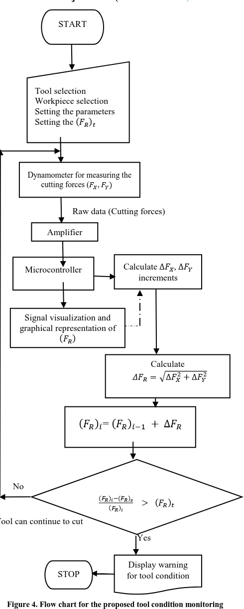
Software developed for the monitoring purpose enables the resultant cutting force data to be used for detecting the tool state/condition. Variations of resultant cutting force signals gathered by 16F877 microcontroller are displayed graphically. The graphical display renders to see the range that the resultant force vary, but it is possible to observe the analogue results as well. Developed software is written in C-Sharp (C#) and runs in Windows environment. Flow chart of the tool condition monitoring software is shown in figure 4.
The inputs of the software are:
Cutting tool-workpiece material
Cutting conditions (v, f, ae, ap)
(FR)t threshold value
Measured cutting parameters and calculated output values:
Cutting forces (FX, FY)
Current cutting force components (FX1, FY1) at
specified flank wear
System alarm for warning the state/condition of the
tool.
In this research, in order not to take the variations of cutting forces in initial stage into consideration as the tool failure warning; average resultant cutting force is calculated along a given period of time. This is necessary since it takes time until the cutting force becomes stable at the start of the cut.
The period along which the average resultant cutting force is calculated, and input to the software. This period and the threshold value were determined after a series of experiments for the appropriate workpiece-cutting tool and the cutting conditions. Tool monitoring system operates by continuously collecting signals of resultant cutting force at the given conditions and then judging whether tool replacement is necessary or not, depending upon the amount of tool wear.
Force signals are highly sensitive carriers of information about the machining process. The resultant cutting force displays, were also reported to provide evidence of the nature of the relationship between force and wear but was affected by cutting conditions.
The variation of the resultant cutting force that exceeds the threshold value indicates the warning for tool replacement. This threshold value was calculated as 150 N for TiAlN coated flat solid carbide end mill in the work done.
The cutting force increments are calculated and compared during the cutting processes. When the
normalized resultant cutting force (FR)n reaches to the
threshold value, a warning is generated. Feed and normal forces after every measurement can be expressed as:
( ) ( )
√ ( )
Where, and are the cutting force increments
calculated from the consecutive measurements and is
the increment of the resultant cutting force. The resultant cutting force after every measurement can be stated in the following form:
√ ( )
And the normalized resultant cutting force can be expressed as:
( ) ( ) ( )
International Journal of Emerging Technology and Advanced Engineering
Website: www.ijetae.com (ISSN 2250-2459,ISO 9001:2008 Certified Journal, Volume 4, Issue 5, May 2014)
[image:7.595.51.276.137.537.2]421
Figure 3. Hardware circuit for the proposed tool conditionmonitoring system of end milling
Where,
( ) = normalized resultant cutting force
( ) = the current resultant cutting force
( ) = the resultant cutting force at the start
( ) threshold of resultant cutting force
The system developed, should be capable of analysing the force variations accurately. In metal cutting processes sudden variations in cutting forces that differ according to the cutting tool, workpiece material or the cutting parameters is usually encountered. Excessive amount of tool wear causes sudden change of the value of the cutting forces much faster than, i.e. changes associated with a variation of depth of cut. In order not to get a false tool wear warning, this increase in cutting forces should continue constantly for a certain period.
V. RESULTS AND DISCUSSION OFTCMSYSTEM
A. Integration and Testing of the TCM System
The cutting conditions for the experiment were as
follows: Spindle speed (v), Feed (fz), Radial depth of cut
(ae), Axial depth of cut (ap). As the wear on the cutting
edge (flank wear in this case) increases, the cutting force increases. The cutting process was paused in every one pass (70 mm) and the flank wear was measured. Thus, the flank wear progression was investigated and wear versus experimental run and resultant cutting force versus experimental run graphs were plotted. Refer figure 7 and figure 8.
B. Tool Condition Monitoring and Tool Failure Experiments
[image:7.595.322.541.516.661.2]Whenever the tool breaks, the contact between the tool and workpiece is lost and a significant drop of cutting force is encountered. If the force increases above the preset threshold and drops suddenly, it is considered to be a tool failure. The variation of resultant cutting force at the moment of tool breakage is shown in figure 6. When the measured force exceed a limit that is predetermined, the tool is assumed to have failed due to excessive wear. In many cases resultant cutting force increment may not be easily separable from those due to other disturbances, for example hard spots in the workpiece material or unexpected change of depth of cut. And also resultant cutting force does not increase significantly, even during breaking of cutting edge. For this reason, if the value of resultant cutting force that exceeded the threshold value stays stable this is accepted as a successful detecting.
International Journal of Emerging Technology and Advanced Engineering
Website: www.ijetae.com (ISSN 2250-2459,ISO 9001:2008 Certified Journal, Volume 4, Issue 5, May 2014)
422
[image:8.595.64.309.128.738.2]Output of the software developed for tool failure detection is shown in figure 5 and figure 6. A warning pops up when the threshold value is reached. The increase and the drop of the cutting force just before the tool failure are obvious in this figure. The software is capable of plotting the variation of resultant cutting force when it is necessary.
Figure 6. Screen shot of cutting force variations in a worn end mill
VI. CONCLUSIONS
The tool wear detection using tool condition monitoring with microprocessor is tested experimentally on AISI-D2 material and performances of this integration are compared and evaluated. These tests were performed in real time with different cutting conditions and several conclusions can be summarized as follows:
With the developed TCM system it is possible to
detect the tool wear on the end mill. Besides, it is also possible to determine in advance the tool failure by setting the threshold value and to find out the moment that the tool wears as per the standard criterion.
There are many methods used in tool condition
monitoring but amongst these methods, cutting force measurements is considered to be the most popular. In the TCM system developed which is based on the cutting force measurement it is observed that resultant force increases as the tool wear progresses consistently.
The resultant cutting force is considered as the
decision making parameter.
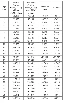
The average percentage error of resultant cutting
force from Table 1, was found to be ± 5% which is well within the acceptable range.
With the developed TCM system to some extent it
was possible to convert the stochastic system into mechanistic system.
No
Tool can continue to cut START
Tool selection Workpiece selection Setting the parameters
Setting the (𝐹𝑅)𝑡
Dynamometer for measuring the cutting forces (𝐹𝑋,𝐹𝑌)𝑋
Amplifier
and filter
Calculate Δ𝐹𝑋,Δ𝐹𝑌
increments Microcontroller
Signal visualization and graphical representation of
(𝐹𝑅)
Calculate 𝛥𝐹𝑅 Δ𝐹𝑋 Δ𝐹𝑌
(𝐹
𝑅)
𝑖=
(𝐹
𝑅)
𝑖−Δ𝐹
𝑅Raw data (Cutting forces)
Yes
(𝐹𝑅)𝑖−(𝐹𝑅)𝑠
(𝐹𝑅)𝑖 (𝐹𝑅)𝑡
Display warning for tool condition STOP
[image:8.595.329.535.223.366.2]International Journal of Emerging Technology and Advanced Engineering
Website: www.ijetae.com (ISSN 2250-2459,ISO 9001:2008 Certified Journal, Volume 4, Issue 5, May 2014)
[image:9.595.38.295.147.723.2]423
TABLE IPer cent Error of Resultant Cutting Forces With and Without Integration of TCM System
Expt. No.
Resultant Cutting
Force, Fr (N)
without TCM system
Resultant Cutting
Force, Fr (N)
with TCM system
Absolute
error % Error
1 76.095 76.564 -0.469 -0.616
2 88.333 95.109 -6.777 -7.672
3 118.292 117.952 0.339 0.287
4 97.119 105.441 -8.321 -8.568
5 99.084 93.676 5.409 5.459
6 85.986 85.141 0.845 0.983
7 98.763 93.850 4.913 4.974
8 88.329 87.509 0.819 0.927
9 106.234 103.251 2.982 2.807
10 88.523 87.386 1.138 1.285
11 109.780 102.635 7.145 6.509
12 124.707 122.182 2.525 2.025
13 122.510 109.944 12.565 10.257
14 82.658 101.850 -19.191 -23.217
15 90.568 95.041 -4.472 -4.938
16 100.725 102.485 -1.760 -1.747
17 101.713 97.870 3.843 3.778
18 104.635 106.833 -2.197 -2.100
19 93.841 94.647 -0.806 -0.859
20 106.094 106.600 -0.507 -0.478
21 119.848 122.852 -3.003 -2.506
22 106.504 110.888 -4.384 -4.116
23 120.108 106.463 13.644 11.360
24 104.870 101.380 3.490 3.328
25 104.268 107.560 -3.291 -3.157
26 99.871 104.670 -4.800 -4.806
27 105.930 106.854 -0.924 -0.872
Figure 7. Resultant cutting forces with and without integration of TCM system
Figure 8. Flank wear progression in an end mill
REFERENCES
[1] Srinivasa Pai, P. and Ramakrishna Rao, P. K., "Acoustic Emission Analysis for Tool Wear Monitoring in Face Milling," International Journal of Production Research, Vol. 40, No. 5, pp. 1081-1093, 2002.
[2] Tseng, P. C. and Chou, A., "The Intelligent On-line Monitoring of End Milling," International Journal of Machine Tools and Manufacture, Vol. 42, No. 1, pp. 89-97, 2002.
[3] Chung, K. T. and Geddam, A., "A Multi-Sensor Approach to the Monitoring of End Milling Operations," Journal of Materials Processing Technology, Vol. 139, No. 1-3, pp. 15-20, 2003. [4] Haber, R. E. and Alique, A., "Intelligent Process Supervision for
Predicting Tool Wear in machining Processes," Mechatronics, Vol. 13, pp. 825-849, 2003.
[5] Romero-Troncoso, R., Herrera-Ruiz, G., Terol-Villalobos, I. and Jauregui-Correa, J., "Driver Current Analysis for Sensorless Tool Breakage Monitoring of CNC Milling Machines," International Journal of Machine Tools and Manufacture, Vol. 43, No. 15, pp. 1529-1534, 2003.
[6] Haber, R. E., Jimenez, J. E., Ronei, P. C. and Alique, J. R., "An Investigation of Tool Wear Monitoring in a High- Speed Machining Process," Sensors and Actuators, Vol. 116, pp. 539-545, 2004.
[7] Axinte, D. and Gindy, N., "Assessment of the Effectiveness of a SpindlePower Signal for Tool Condition Monitoring in Machining Processes," International Journal of Production Research, Vol. 42, No. 3, pp. 2679-2691, 2004.
[8] Choi, Y., Narayanaswami, R. and Chandra, A., "Tool Wear Monitoring in Ramp Cuts in End Milling using the Wavelet Transform," International Journal of Advanced Manufacturing Technology, Vol. 23, pp. 419-428, 2004.
[9] Shao, H., Wang, H. L. and Zhao. X. M., "A Cutting Power Model for Tool Wear Monitoring in Milling," International Journal of Machine Tools and Manufacture, Vol. 44, No. 14, pp. 1503-1509, 2004.
[10] Song, D. Y., Otani, N., Aoki, T., Kamakoshi, Y., Ohara, Y. and Tamaki, H., "A New Approach to Cutting State Monitoring in End Mill Machining," International Journal of Machine Tools and Manufacture, Vol. 45, No. 7-8, pp. 909-921, 2005.
[11] Chen, J. C. and Chen, J. C., "An Artificial-Neural-Networks-Based In-Process Tool Wear Prediction System in Milling Operations," International Journal of Advanced Manufacturing Technology, Vol. 25, pp. 427-434, 2005.
[12] Cho, S., Asfour, S., Onar, A. and Kaundinya, N., "Tool Breakage Detection using Support Vector Machine Learning in a Milling Process," International Journal of Machine Tools and Manufacture, Vol. 45, No. 3, pp. 241-249, 2005.
0 20 40 60 80 100 120 140
1 5 9 13 17 21 25
Re su lt an t cu tt in g f o rc e , Fr (N) Experimental run Resultant Cutting Force, Fr (N) with TCM system Resultant Cutting Force, Fr (N) without TCM system 0 0.1 0.2 0.3 0.4 0.5
0 10 20 30
[image:9.595.39.292.164.579.2]International Journal of Emerging Technology and Advanced Engineering
Website: www.ijetae.com (ISSN 2250-2459,ISO 9001:2008 Certified Journal, Volume 4, Issue 5, May 2014)
424
[13] Milfelner, M., Cus, F. and Balic, J., "An Overview of Data Acquisition System for Cutting Force Measuring and Optimization in Milling," Journal of Materials Processing Technology, Vol. 164-165, pp. 1281-1288, 2005.
[14] Li, H. Z., Zeng, H. and Chen, X. Q., "An Experimental Study of Tool Wear and Cutting Force Variation in the End Milling of Inconel 718 with Coated Carbide Inserts," Journal of Materials Processing Technology, Vol. 180, No. 1-3, pp. 296-304, 2006. [15] Amer, W., Grosvenor, R. I. and Prickett, P. W., "Sweeping Filters
and Tooth Rotation Energy Estimation (TREE) Techniques for Machine Tool Condition Monitoring," International Journal of Machine Tools and Manufacture, Vol. 46, No. 9, pp. 1045-1052, 2006.
[16] Ritou, M., Garnier, S., Furet, B. and Hascoet, J. Y., "A New Versatile In-process Monitoring System for Milling," International Journal of Machine Tools and Manufacture,Vol. 46, No. 15, pp. 2026-2035, 2006.
[17] Yesilyurt, I., "End Mill Breakage Detection using Mean Frequency Analysis of Scalogram," International Journal of Machine Tools and Manufacture, Vol. 46, No. 3-4, pp. 450-458, 2006.
[18] Yesilyurt, I. and Ozturk, H., "Tool Condition Monitoring in Milling using Vibration Analysis," International Journal of Production Research, Vol. 45, No. 4, pp. 1013-1028, 2007. [19] Lee, K. J., Lee, T. M. and Yang, M. Y., "Tool Wear Monitoring
System for CNC End Milling using a Hybrid Approach to Cutting Force Regulation," International Journal of Advanced Manufacturing Technology, Vol. 32, pp. 8-17, 2007.
[20] Amer, W., Grosvenor, R. and Prickett, P., "Machine Tool Condition Monitoring using Sweeping Filter Techniques," Journal of Systems and Control Engineering, Vol. 221, pp. 103-117, 2007. [21] Dini, G. and Tognazzi, F., "Tool Condition Monitoring in End
Milling using a Torque-Based Sensorized Toolholder," Journal of Engineering Manufacture, Vol. 221, pp. 11-23, 2007.
[22] Bassiuny, A. M. and Xiaoli, L., "Flute Breakage Detection during End Milling using Hilbert-Huang Transform and Smoothed Nonlinear Energy Operator," International Journal of Machine Tools and Manufacture, Vol. 47, No. 7, pp. 1011-1020, 2007. [23] Bhattacharyya, P., Sengupta, D. and Mukhopadhyay, S., "Cutting
Force-Based Real-Time Estimation of Tool Wear in Face Milling using a Combination of Signal Processing Techniques," Mechanical Systems and Signal Processing, Vol. 21, pp. 2665-2683, 2007.
[24] Ghosh, N., Ravi, Y. B., Patra, A., Mukhopadhyay, S., Paul, S., Mohanty, A. R. and Chattopadhyay, A. B., "Estimation of Tool Wear during CNC Milling using Neural Network-Based Sensor Fusion," Mechanical Systems and Signal Processing, Vol. 21, No. 1, pp. 466-479, 2007.
[25] Hongrui, C., Xuefeng, C., Yanyang, Z., Feng, D., Huaxin, C., Jiyong T. and Zhengjia, H., "End Milling Tool Breakage Detection using Lifting Scheme and Mahalanobis Distance," International Journal of Machine Tools and Manufacture, Vol. 48, No. 2, pp. 141-151, 2008.
[26] Onwubolu, G. C., Buryan, P. and Lemke, F., "Modeling Tool Wear in End Milling using Enhanced GMDH Learning Networks," International Journal of Advanced Manufacturing Technology, Vol. 39, pp. 1080-1092, 2008.
[27] Xiaoli, L., Gaoxiang, O. and Zhenhu, L., "Complexity Measure of Motor Current Signals for Tool Flute Breakage Detection in End Milling," International Journal of Machine Tools Manufacture, Vol. 48, No. 3-4, pp. 371-379, 2008.
[28] Bhattacharyya, P., Sengupta, D., Mukhopadhyay, S. and Chattopadhyay, A. B., "On-line Tool Condition Monitoring in Face Milling using Current and Power Signals," International Journal of Production Research, Vol. 46, No. 4, pp. 1187-1201, 2008.
[29] Zhang, J. Z. and Chen, J. C., "Tool Condition Monitoring in an End Milling Operation Based on the Vibration Signal Collected Through a Microcontroller- Based Data Acquisition System," International Journal of Advanced Manufacturing Technology, Vol. 39, pp. 118-128, 2008.
[30] Zhu, K., Wong, Y. S. and Hong, G. S., "Wavelet Analysis of Sensor Signals for Tool Condition Monitoring: A Review and Some New Results," International Journal of Machine Tools and Manufacture, Vol. 49, No. 7-8, pp. 537-553, 2009.
[31] Zuperl, U., Cus, F. and Kiker, E., "Adaptive Network Based Inference System for Estimation of Flank Wear in End Milling," Journal of Materials Processing Technology, Vol. 209, No. 3, pp. 1504-1511, 2009.
[32] Franco-Gasca, L. A., Romero-Troncoso, R. J., Herrera-Ruiz, G. and Peniche-Vera, R. R., "FGPA Based Failure Monitoring System for Machining Processes," International Journal of Advanced Manufacturing Technology, Vol. 40, pp. 676-686, 2009.
[33] Cho, S., Binsaeid, S. and Asfour, S., "Design of Multisensor Fusion-Based Tool Condition Monitoring System in End Milling," International Journal of Advanced Manufacturing Technology, Vol. 46, pp. 681-694, 2010.
[34] Ghani, J. A., Rizal, M., Nuawi, M. Z., Ghazali, M. J. and Haron, C. H. C., "Monitoring On-lIne cutting Tool wear using Low-Cost Technique and User Friendly Graphical user Interface," Wear, Vol. 271, No. 9-10, pp. 2619-2624, 2011.
[35] Prickett, P. W., Siddiqui, R. A. and Grosvenor, R. I., "A Microcontroller Based End Milling Cutter Monitoring and Management System," International Journal of Advanced Manufacturing Technology, Vol. 55, pp. 855-867, 2011. [36] Zhang, C., Liu, X., Fang, J. and Zhou, L., "A New Tool Wear
Estimation Method Based on Shape Mapping in the Miling Process," International Journal of Advanced Manufacturing Technology, Vol. 53, pp. 121-130, 2011.
[37] Prickett, P. W., Siddiqui, R. A. and Grosvenor, R. I., "The Development of an End Milling Process Depth of Cut Monitoring System," International Journal of Advanced Manufacturing Technology, Vol. 52, pp. 89-100, 2011.
[38] Ai, C. S., Sun, Y. J., He, G. W., Ze, X. B., Li, W. and Mao, K., "The Milling Tool Wear Monitoring using the Acoustic Spectrum," International Journal of Advanced Manufacturing Technology, Vol. 61, pp. 457-463, 2012.
[39] Tansel, I. N., Li, M., Demetgul, M. and Bickraj, K., "Detecting Chatter and Estimating Wear from the Torque of End Milling Signals by using Index Based Reasoner (IBR)," International Journal of Advanced Manufacturing Technology, Vol. 58, pp. 109-118, 2012.
![Figure 1. Cutting-force components acting on one tooth of an end mill [40]](https://thumb-us.123doks.com/thumbv2/123dok_us/8715298.882888/4.595.62.266.647.748/figure-cutting-force-components-acting-tooth-end.webp)