International Journal of Emerging Technology and Advanced Engineering
Website: www.ijetae.com (ISSN 2250-2459, ISO 9001:2008 Certified Journal, Volume 8, Issue 3, March 2018)
157
Fabrication and Performance Analysis of A Retrofitting Type
Air Inducing Mechanically Agitated Contactor Aeration
Enkuahone Abebe
1, R. Srinu Venkat Rao
2,
Tsedale Tesfaye
3 1, 2, 3Department of Chemical Engineering, College of Engineering, Debre Berhan University, Debre Berhan, Ethiopia
Abstract-- Attempts have been made to convert a conventional mechanically agitated vessel into an air inducing reactor and to simplify the mechanism and fabrication of self-air inducing impeller system. A specially designed tube bundle fabricated using L-shaped tubes was used as the primary impeller for inducing air which when attached to the impeller shaft of a conventional agitated vessel converted it into an air inducing reactor. Two different tube bundles (3-Ltubes and 6-L tubes) were used for this study. A straight turbine and disc-turbine with six-blades were used as the secondary impellers. The primary impellers were used separately and combined with one secondary impeller at a time. Critical speed for the induction of air, gas holdup and power consumption per unit volume of the working fluid were observed by varying the impeller combination, bottom clearance, submergence depth of the orifice and inter-impeller distance in order to observe the hydrodynamic aspects and performance of the proposed system. It was found that the critical speed for induction of air into the reactor increased with increase in submergence depth of the orifice and decreased with bottom clearance when water was used as the working fluid.
Keywords: Air inducing impeller; self-ingesting reactor; Gas holdup; Hydrodynamics.
I. INTRODUCTION
A gas inducing mechanically agitated contactor or reactor is basically a gas liquid contacting equipment with or without the presence of solids which lacks the bottom spurge for air admission and instead it sucks the gas through its rotor or the impeller when it rotates as a result of the geometrical features imparted to them and also to the entire reactor set up. The very simple classification given to the air inducing reactors is dead end systems and open end systems. A typical dead end system recycles the unreacted gas internally through the reactor and ensures its effective utilization. In contrast the open end systems are in contact with the atmosphere and virtually there will be no recycle of the reactant gases. The open end systems are extensively used when air is being used as the gaseous reactant where a recycle operation is not necessary. [7][28] In chemical process industries, gas liquid contacting, with or without solids is one of the most important operations. In many of the cases, the per pass conversion of gas is fairly low and is also desirable to recycle the unreacted gas back to the reactor because the gas may be highly toxic, may pose safety problems or of economic considerations.
Typical examples include alkylation, ethoxylation, hydrogenation, chlorination, ammonolysis, oxidation, and so forth. In such a situation the importance of a reactor system which recycles the excess unreacted gas without an external compressor loop is more significant and a kind of that system can ensure plant and environmental safety into a larger extend in an economical way. [2][23]
The use of gas inducing reactors gaining industrial importance now a day as it is eliminating the wear and tear problems with the Spurger holes and the blockage apart from the economic and environmental benefits. The absence of the expensive compressor in the external loop make a gas inducing mechanically agitated contactor (GIMAC) less capital and less power consuming and an effective reactor system for gas liquid solid contacting.[5][30] These kinds of contactors can also produce higher mass and heat transfer rates when comparing with other counterparts. It is also been proved that the air inducing systems are highly efficient in the waste water treatment. [4][19]
II. MATERIALS AND METHODS
International Journal of Emerging Technology and Advanced Engineering
Website: www.ijetae.com (ISSN 2250-2459, ISO 9001:2008 Certified Journal, Volume 8, Issue 3, March 2018)
158
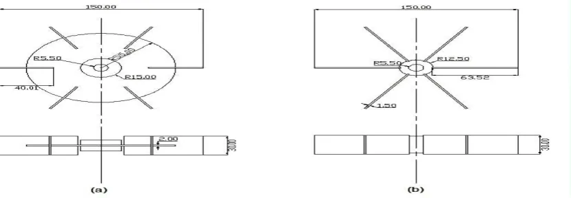
The tubes were arranged in an equiangular radial array. The circular blocks were having holes at the center to get inserted to the shaft. The submersion depth of the horizontal part of the tubes can also be varied by sliding it on the shaft. In the experimentation two kinds of tube bundles which are of three and six in number can be used for better analysis of the system behavior. Detailed scale diagrams of the tube bundles with its dimensions in millimeters are given in the following figures.
For the proposed study the following secondary impellers can be used [28].
1. Turbine impeller 2. Disc turbine impeller
[image:2.595.46.527.287.552.2]The drawing of the above two impellers were given in the following figures with its dimensions in millimeters. The combination of the primary and the secondary impeller made the system to act as a dual impeller agitated reactor system. Using the above set up all the required proposed studies can be completed. For the mass and heat transfer studies the thermocouples and the dissolved oxygen probes have to be incorporated in the system appropriately. [14]
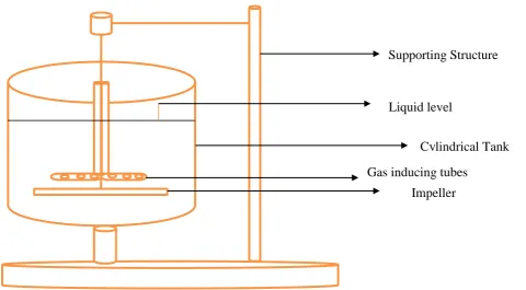
Figure 1: Gas inducing mechanically agitated contactor
A conventional baffled agitated vessel was retrofitted with a specially designed air inducing tube bundle and the schematic diagram of the experimental setup is shown in figure flat bottomed cylindrical agitated vessel made up of acrylic material, was mounted on a torque table fixed to the floor. Four vertical baffles were fitted to seized the vortex formation and ensure effective mixing of the working fluid. The impeller, mounted on a vertical solid shaft, was driven by a 2hp alternating current (AC) induction motor. The rotational speed of the impeller was regulated by a speed control drive and the power consumed by the motor was measured using two digital watt meters. The shaft power was calculated from the counter weight on a load cell which was connected to the torque table.
The impeller speed was measured using a digital tachometer. Two tube bundles (with 3-tubes and 6-tubes) were fabricated by bending the tube to L-shape and attaching them to the impeller shaft and used to induce the air into the vessel. During the experiment, for a given level of liquid in the tank, the impeller immersion depth and bottom clearance were fixed by adjusting the position of the impeller. The rotational speed of impeller was gradually increased using speed control drive until the start of the suction of air and the corresponding speed (critical speed) was measured using tachometer. Critical speed, gas holdup and power consumption (both motor power and shaft power) were measured by varying the total liquid height, orifice submersion depth, impeller combination and bottom clearance.
Impeller
Gas inducing tubes
Liquid level
International Journal of Emerging Technology and Advanced Engineering
Website: www.ijetae.com (ISSN 2250-2459, ISO 9001:2008 Certified Journal, Volume 8, Issue 3, March 2018)
159
[image:3.595.76.520.99.248.2]Figure 2: (a) Single tube with orifices, (b) plan view of a 3 tube set, (c) elevation of 3 tube set, (d) plan view of 6 tube set
Figure 3: Types of Solid Impellers (a) Disc turbine impeller, (b) Turbine impeller
The solid suspension studies could be made at various solid loadings with the respective system conditions. The solid loading can be varied from 1% to 15% and the particle size can be varied from 100 micron to 1000 micron. The tank should be fitted with baffles to ensure that the vortex formation is seized and medium was effectively mixed. Water can be used as the working fluid in case of the analysis of the Newtonian systems.
[image:3.595.105.520.280.424.2]International Journal of Emerging Technology and Advanced Engineering
Website: www.ijetae.com (ISSN 2250-2459, ISO 9001:2008 Certified Journal, Volume 8, Issue 3, March 2018)
[image:4.595.47.558.163.667.2]160
Table 1:A detailed technical specification of the experimental setup]
III. RESULT AND DISCUSSION
Critical Speed
From the results, it was observed that the critical speed was found to increase with increase in impeller immersion depth for all the impeller assemblies used in this study.
This is due to the fact that an increase in impeller immersion depth increases the centrifugal force required to overcome the stagnation pressure. The impeller immersion depth decreases as the bottom clearance increases and hence the critical speed decreases with increase in bottom clearance.
Tank
Internal diameter of the tank 455 mm
Depth of the tank 570 mm
Thickness of the tank wall 12 mm
Baffle width 40 mm
Diameter of the shaft 10mm
L-shaped tube bundle
Outer diameter of the tube 10 mm
Inner diameter of the tube 7 mm
Height of vertical section 345 mm
Length of horizontal section 140 mm
Number of tubes 3 and 6
Diameter of the orifice 2 mm
Inter orifice distance 15 mm
Impellers
Type of impellers Turbine, Disc turbine
Diameter of the impeller 150 mm
Width of the impeller 30 mm
Thickness of the impeller 1.5 mm
International Journal of Emerging Technology and Advanced Engineering
Website: www.ijetae.com (ISSN 2250-2459, ISO 9001:2008 Certified Journal, Volume 8, Issue 3, March 2018)
161
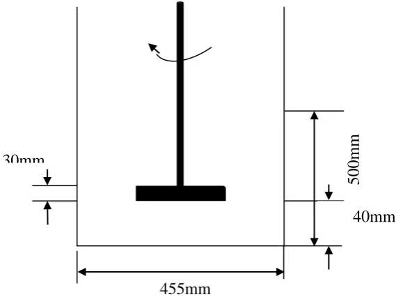
[image:5.595.145.430.158.371.2]Calculation on Critical Impeller Speed, Ncs
Figure 4: Diagram for impeller
Based on Ncs proposed by Sawant and Joshi [1].
Ncs2DI2/g*h*(µ/µw)0.11=0.21………1
From the reactor the impeller diameter (DI) is 150mm. where, h=500mm, is the impeller submersion depth, DI= impeller diameter, µ is the liquid phase viscosity, µ water is the water viscosity while g is the acceleration due to gravity.
For the present stirred tank arrangement, h =18.3 mm, DI = 30 mm and the liquid phase was water, µ/ µ water = 1, Based on Ncs proposed by Sawant and Joshi [1], and given as:
(N2cs*DI2/gh)*(µ/ µw)2=0.21………2
Where, h is the impeller submersion depth, DI = impeller diameter, µ is the liquid phase viscosity, µ water is the water viscosity while g is the acceleration due to gravity. For the present stirred tank arrangement, h=500mm, DI = 150 mm and the liquid phase was water,
µ/µw=1, Ncs= (0.21gh) 2/DI, Substituting the above value the Ncs =19,659.3 m/min. From our system, h=500mm, g=9810 mm/s2 and substitute the above equation. However, this Ncs only valid if speed loss coefficient lie between 0 and 1 (0<K<1).
In order to prove this, Bernoulli equation is used as a basis given as:
gh+P2/L= P2/L+U12/2+ghf1………3
Where, u is a relative velocity between gas outlet and the liquid and given as u=πDIINsK
Where;
Ns=impeller stirring speed (rpm)
K=impeller speed loss coefficient
hf1=energy loss in the turbulent field
DI = the impeller diameter at gas outlet orifices; Thus,
Rearranging the above equation
( )
455mm
40mm
500mm
International Journal of Emerging Technology and Advanced Engineering
Website: www.ijetae.com (ISSN 2250-2459, ISO 9001:2008 Certified Journal, Volume 8, Issue 3, March 2018)
162
For gas to flow from the headspace to the liquid at the gas outlet orifice, P2-P1≥0, thus at critical impeller speed, Ns=Ncs, thus P2=P and equation becomes:
√ ( )
In the case of turbulent flow, hf1≤gh. Thus, gh-hf1˷gh. Therefore, Equation the equation is reduced to:
√
In this case K=0.98, Thus confirming 0<K<1
Power Consumption
The prediction of the power for gassed systems is only possible when the agitator and the process hydrodynamics are understood and predictable.
The power number, NP, which gives an indication of the power requirement for mixing is given by:
[image:6.595.87.511.356.666.2]Np=P/
l*Ns
3*DI
5………..7
Table 2:
Power consumption per unit volume of liquid, W/m3
Power consumption per unit volume of liquid, W/m3 Impeller immersion depth, cm
0 10
100 15
200 20
300 25
400 30
500 35
600 40
700 50
Figure 5: Power consumption versus impeller immersion depth for a bottom clearance of 15cm
Since the increase in impeller immersion depth increases the hydrostatic pressure at the orifice of the primary impeller and leads to higher critical speed and higher power consumption. Figure 2 shows the effect of impeller immersion depth on power consumption per unit volume of liquid for a bottom clearance of 15 cm.
The addition of secondary impeller, irrespective of the type of assembly, increases the total mass of the rotor and hence the power consumption is also increased. For a given liquid level in the tank, the power consumption decreases with increase in bottom clearance of the primary impeller for all the impeller assemblies studied.
0
200
400
600
800
1 2 3 4 5 6 7 8
P
ow
er
c
on
su
m
p
sion
p
er
u
n
it
volu
m
e
of
li
q
u
id
,
W/m
3
Impeller immersion depth, cm
International Journal of Emerging Technology and Advanced Engineering
Website: www.ijetae.com (ISSN 2250-2459, ISO 9001:2008 Certified Journal, Volume 8, Issue 3, March 2018)
163
Gas holdup
Transient Gas-liquid Mass Transfer Measurements These measurements are generally made using a dissolved oxygen tension (DOT) probe to follow the transient of oxygen transferred to or from the liquid following a step change in the inlet conditions due to a step change in either the inlet gas phase composition or the pressure. DOT probes obtained commercially are of two general types: galvanic or polarographic. Oxygen sensitive electrodes consist usually of two metal electrodes in contact with an electrolyte and separated from the test medium by an oxygen permeable membrane. The galvanic types are simple electro-chemical cells in which oxygen is reduced at an inert cathode according to the equation. The current produced by the galvanic reaction is limited by the rate of oxygen diffusion across the membrane, which is proportional to the oxygen concentration in the test medium. With the polarographic type electrodes a polarizing voltage is applied across the electrodes and current flows in the presence of oxygen, which is proportion to the partial pressure of oxygen in the test medium. For example a polarographic probe with a silver anode, a platinum cathode and a potassium chloride solution electrolyte causes oxygen to be reduced at the Platinum cathode according to the above equation. The cell reaction sets up a current flow due to the conduction of electrons from anode to cathode. The hydroxyl ions in the cell are entirely from oxygen transported across the membrane since this is designed to be impermeable to these ions. The probes consume oxygen. This means that if the fluid turnover at the membrane is not sufficiently fast then local oxygen depletion will occur. This means that the probe position is important.
[image:7.595.65.527.555.694.2]Also the faster the probe response is, generally, the more oxygen they consume and the more they are sensitive to the local hydrodynamics. It measures a local concentration. This concentration may only be representative of the whole vessel if the liquid phase mixing is fast compared to the mass transfer. In earlier work, Cooke et al. (1988) showed that the mixing had to be approximately three times faster than the mass transfer in order for the “well-mixed” liquid with respect to the mass transfer assumption to be realistic. [27]The probe reading is proportional to the partial pressure of oxygen which is required to produce the equilibrium oxygen concentration in the solution, regardless of its solubility in the solution at a given temperature. Hence, if the solubility changes, due changes in composition of the solute, the equilibrium reading will not change. This is important in systems like fermentations where changes in glucose concentrations with time can have a marked effect on oxygen solubility with a consequent change in calibration. Following from the above, they do not differentiate between the oxygen partial pressure in the liquid and the oxygen partial pressure in the gas. They measure both without distinction. It has been showed that ignoring the influence of the gas phase contribution to the probe readings could lead to an overestimation of the overall mass transfer factor kLa. Votruba et al. (1977 and 1978) suggested a method of correcting for the effect of local hold up on the probe. To minimize the effect of gas bubbles “seen” by the probe membrane the probe needs to be orientated so that the probe. Dynamic response analysis using DOT probes consists of analyzing the response of probes to a step change in either the inlet gas phase composition or the pressure. [18]
Table 3:
Evaluation of fractional gas holdup of an impeller and immersion depth, cm
Fractional gas holdup at 600 rpm clearance of 5cm
0 10
0.05 15
0.1 20
0.15 25
0.2 30
International Journal of Emerging Technology and Advanced Engineering
Website: www.ijetae.com (ISSN 2250-2459, ISO 9001:2008 Certified Journal, Volume 8, Issue 3, March 2018)
[image:8.595.68.525.106.269.2]164
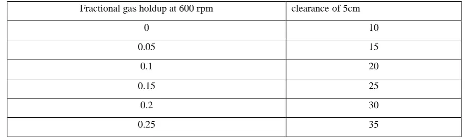
Figure 6: Fractional gas holdup at 600 rpm for a bottom clearance of 5cm
The gas holdup increases with increase in impeller speed due to higher induction rate if air. Figure 8 shows the dependence of fractional gas holdup on impeller speed for an immersion depth of 15 cm. At all rotational speeds of the impeller greater than the critical speed for a given liquid level, the increase in orifice submergence leads to decrease in the gas holdup in the vessel.
The gas holdup was observed for both the tube sets (tube sets with 3 tubes and 6 tubes) for all the immersion depths studied. It was noticed that the gas holdup was more for tube set with 6 tubes as compared with the tube set with 3 tubes. Figure 8 shows the effect of impeller immersion depth on fractional gas holdup at 600 rpm for a bottom clearance of 5 cm.
Rate of Gas Induction Based on Bernoulli equation;
P1/ +U1/2+gh1= P2/ +U2/2+gh2………7
Where,
P1, P2= pressure at location 1 and 2
U1, U2= fluid velocity at location 1 and 2
h1, h2= static head at location 1 and 2
= density of the dispersed phase, in this case the gas phase
g = gravitational acceleration (9.81 m/s2)
In agitated tank reactor, the rate gas induction can be estimated once the Ncs is obtained, thus the Bernoulli equation becomes;
P1/G + 0.5 (QG Orifice) 2 +ghf2= P1/G…………..………8
Where,
QG = gas volumetric flow rate
A Orifice = gas outlet orifice area
UG = gas phase density
hf2 = energy loss during gas flow through the impeller shaft from inlet to exit
Substitute Equation (2) into (1), yields;
QG=2Aorfice2 *(
)………9
Gas liquid stirred vessels are widely employed to carry out chemical reactions involving a gas reagent and a liquid phase. The usual way for introducing the gas stream into the liquid phase is through suitable distributors placed below the impeller. An interesting alternative is that of using “self-ingesting” vessels where the headspace gas phase is injected and dispersed into the vessel through suitable surface vortices.
In this work the performance of a Long Draft Tube Self-ingesting Reactor dealing with gas-liquid-solid systems, is investigated. Preliminary experimental results on the effectiveness of this contactor for particle suspension and gas-liquid mass transfer performance in presence of solid particles are presented.
International Journal of Emerging Technology and Advanced Engineering
Website: www.ijetae.com (ISSN 2250-2459, ISO 9001:2008 Certified Journal, Volume 8, Issue 3, March 2018)
165
It is found that the presence of low particle fractions causes a significant increase in the minimum speed required for vortex ingestion of the gas. Impeller pumping capacity and gas-liquid mass transfer coefficient are found to be affected by the presence of solid particles, though to a lesser extent than with other self- ingesting devices. The hold-up values observed at the various agitation speeds. As it can be seen, gas hold-up increases while increasing agitation speed, in agreement with expectations, while the presence of suspended particles appears to have no influence on total gas hold-up. However, visual observation of the reactor shows that the presence of particles modifies the gas hold-up distribution inside the reactor, sensibly reducing the gas fraction inside the annular section and increasing that in the down comer, though the total gas hold-up remains constant. This, in turn, may reduce the mass transfer efficiency of the system. The reason behind the slight decrease is clearly the larger gas hold-up at higher rotational speeds. The relatively constant value observed may anyway be regarded as an indication of hydrodynamic robustness. It is worth noting that the increase of power consumption due to the presence of just 1 % wt. of solid particles is surprisingly high, being of the order of 25%. In order to explain such a large sensitivity of power on particles presence one may postulate that particles concentrate in the annular section and give rise to a sort of fluid friction increase that reduces fluid recirculation. This in turn lowers gas down-flow in the draft tube, hence increasing the power number of the lowest radial turbine. Considering that the lowest radial turbine having the largest diameter is the one that contributes the most to power consumption, the above chain of effects might well explain the observed dramatic increase of this last.As explained in the discussion of the gas holdup, the presence of solids which accumulate in the annulus strongly modifies the gas hold up distribution inside the reactor and hence the flow rate of ingested gas also is reduced, resulting in a lower interfacial area. This would seem to be the primary mechanism by which the volumetric gas–liquid mass transfer coefficient is reduced by the presence of solids in a vortex ingesting gas– liquid–solid reactor. A secondary effect may be that of turbulence damping by the particles resulting in lower values of kLa. [6]
IV. CONCLUTIONS AND RECOMENDATIONS
The hydrodynamic characteristics of the proposed gas inducing impeller system were investigated for suction and distribution of atmospheric air into the working fluid (water). Three L-shaped tube-sets, one with 3-tubes and 6-tubes, were fabricated and used as the primary impeller for inducing air and the results were found to be satisfactory.
International Journal of Emerging Technology and Advanced Engineering
Website: www.ijetae.com (ISSN 2250-2459, ISO 9001:2008 Certified Journal, Volume 8, Issue 3, March 2018)
166
REFERENCES
[1] Sawant, S.B. and J.B. Joshi, Critical impeller speed for the onset
of gas induction in gas-inducing types of agitated contactors. The Chemical Engineering Journal, 1979. 18(1): p. 87-91.
[2] Alaa K. Mohammed, Hassanin Ali Hussen and Safa Abid
Al-Rassul, (2008), Performance of Gas Induction in a Dual Impeller Agitated Bioreactor, Al-Khwarizmi Engineering Journal, 4, 1-8.
[3] Andrzej Heim, Andrzej Kraslawski, Edward Rzyski, Jacek
Stelmach, (1995), Aeration of bioreactors by self-aspirating impellers, The Chemical Engineering Journal, 58, 59-63.
[4] Ashwin W. Patwardhan and Jyeshtharaj B. Joshi, (1999), Design
of Gas-Inducing Reactors, Ind. Eng. Chem. Res38, 49-80.
[5] Bawadi Abdullah, Chirag Dave, Tuan-Huy Nguyen, Cyrus G.
Cooper, Adesoji A.Adesina, (2011), Electrical resistance tomography-assisted analysis of dispersed phase hold-up in a gas-inducing mechanically stirred vessel, Chemical Engineering Science, 66, 5648-5662.
[6] B.N. Murthy, N.A. Deshmukh, A.W. Patwardhan, J.B. Joshi,
(2007), Hollow self-inducing impellers: Flow visualization and CFD simulation, Chemical Engineering Science, 62, 3839– 3848.
[7] B.N. Murthy, R.B. Kasundra, J.B. Joshi, (2008), Hollow
self-inducing impellers for gas–liquid–solid dispersion: Experimental and computational study Chemical Engineering Journal, 141,332– 345.
[8] C. Aldrich and J.S.J. van Deventer, (1994), Observations on
induced aeration in agitated slurries, The Chemical Engineering Journal, 54, 199-205.
[9] E.Dietrich, C.Mathieu, H. Delmas and J.Jenck, (1992)
Raney-nickel catalyzed hydrogenations: Gas-liquid mass transfer in gas-induced stirred slurry reactors, Chemical engineering science, 47, 3597-3604.
[10] Fan Ju, Zhen-Min Cheng, Jian-Hua Chen, Xiao-He Chu,
Zhi-Ming Zhou, Pei-Qing Yuan, (2009), a novel design for a gas-inducing impeller at the lowest critical speed, Chemical Engineering Research and Design, 87, 1069-1074.
[11] F. Scargiali, R. Russo, F. Grisafi, A. Brucato, (2007), Mass
transfer and hydrodynamic characteristics of a high aspect ratio self-ingesting reactor for gas–liquid operations, Chemical Engineering Science, 62, 1376 – 1387.
[12] Jyh-Herng Chen, Yung-Chien Hsu, Y.-F. Chen, Chih-Chu Lin,
(2003), Application of gas-inducing reactor to obtain high oxygen dissolution in aeration process, Water research, 37, 2919–2928.
[13] Kaliannagounder Saravanan, Vishwas D. Mundale, Ashwin W.
Patwardhan, and Jyeshtharaj B. Joshi, (1996) Power Consumption in Gas-Inducing-Type Mechanically Agitated Contactors, Ind. Eng. Chem. Res, 35, 1583-1602.
[14] Kaliannagounder Saravanan, Veerappan Ramamoorthy,
Kothandaraman Chandramohan, (2009) Gas holdup in multiple impeller agitated vessels 3, 49–59.
[15] K.C. Ruthiya, J. van der Schaaf, B.F.M. Kuster, J.C. Schouten,
(2003), Mechanisms of physical and reaction enhancement of mass transfer in a gas inducing stirred slurry reactor Chemical Engineering Journal, 96, 55–69.
[16] M. Cooke, P.J. Heggs, T.L. Rodgers, (2007),The effect of solid on
dense phase gas fraction and gas liquid mass transfer at condition close to heterogeneous regime in a mechanically agitated vessel, Chemical engineering research and design, 86, 869–882.
[17] M. Jafari and J. S. Soltan Mohammad Zadeh, (2005), Mixing
time, homogenization energy and residence time distribution in a gas-induced contactor, chemical engineering research and design, 83, 452-459.
[18] Mounir Bouaifi, Michel Roustan, (2001), Power consumption,
mixing time and homogenization energy in dual-impeller agitated gas–liquid reactors, Chemical Engineering and Processing, 40, 87–95.
[19] Mousa Jafari, Jafar S. Soltan Mohammad Zadeh, (2004), Power
consumption and onset speed for gas induction in a gas-induced contactor, Chemical Engineering Journal, 103, 1-5.
[20] N. A. Deshmukh, S. S. Patil and J. B. Joshi, (2006), Gas induction
characteristics of hollow self-inducing impeller, Chemical Engineering Research and Design, 84(A2): 124–132.
[21] R. Lemoine, B. Fillion, A. Behkish, A.E. Smith, B.I. Morsi,
(2003),Prediction of the gas liquid volumetric mass transfer coefficients in surface-aeration and gas-inducing reactors using neural networks, Chemical Engineering and Processing, 42, 621- 643.
[22] Romain Lemoine, Badie I. Morsi, (2005), An algorithm for
predicting the hydrodynamic and mass transfer parameters in agitated reactors, Chemical Engineering Journal, 114, 9–31.
[23] R.N. Sharma, Abdulla Shaikh, (2003), Solid suspension in stirred
tanks with pitched blade turbines, Chemical engineering science, 58, 2123–2140.
[24] Rouzbeh Jafari, Philippe A. Tanguy, and Jamal Chaouki, (2012),
Characterization of minimum impeller speed for suspension of solids in liquid at high solid concentration, using gamma-ray densitometry, International journal of chemical engineering, 53, 1-10.
[25] S.E. Forrester, C.D. Reilly, (1994), Modelling of increased gas
capacity of self-inducing impellers, Chemical engineering science, 49, 5709-5718.
[26] S.E Forrester, CD Reilly, KJ Carpenter, (1996), Gas inducing
impeller design and performance characteristics, Chemical engineering science, 56, 603-615.
[27] S. Poncin,C. Nguyena, N. Midouxa, J. Breysse, 2002),
Hydrodynamics and volumetric gas–liquid mass transfer coefficient of a stirred vessel equipped with a gas-inducing impeller, Chemical Engineering Science, 57, 3299 – 3306.
[28] Tomas Moucha, Vaclav Linek, Eva Prokopova, (2003), Gas
hold-up, mixing time and gas–liquid volumetric mass transfer coefficient of various multiple-impeller configurations: Rushton turbine, pitched blade and technology mixture impeller and their combinations, Chemical Engineering Science, 58, 1839 – 1846.Yoggaang Zhu, Jie Wu, (2002),Critical impeller speed for suspending solids in aerated agitation tanks, Canadian journal of chemical engineering, 80, 1-6.
[29] Development and Performance analysis of Novel Agitated
Vessel, C.Gomadurai, K.Saravanan, Eldho Abraham and N. Deepa, Korean Journal of Chemical Engineering (Springer Link).
[30] Hydrodynamic Studies on Air-Inducing Impeller System,
C.Gomadurai, K.Saravanan, Eldho Abraham and N. Deepa, International Journal of ChemTech Research, CODEN (USA): IJCRGG ISSN : 0974-4290 , Vol.6, No.10, pp: 4471-4474, September 2014.
[31] A review on Hydrodynamics of Gas Inducing Mechanically
Agitated Contactors, Eldho Abraham, International Journal of Technochem Research, ISSN 2395-4248,Vol 1, No 1, 35 – 49, 2015.
[32] Study on Gas Induction and Comparison of Power Consumption
of Gas Inducing Mechanically Agitated Contactors with the Gas Sparging Mechanically Agitated contactors, Eldho Abraham, International Journal of Technochem Research, ISSN 2395-4248, Volume 1, No 1, 25 – 34, 2015.
[33] 34.https://sphinxsai.com/2014/RACE/1/(4471-4474)%
20014.pdf
[34] https://pure.unipa.it/it/publications/gas-liquid-solid
-operation-of-a-long-draft-tube-self-ingesting-re-2
[35] https://pure.unipa.it/en/publications/gas-liquid-solid-
![Table 1: A detailed technical specification of the experimental setup]](https://thumb-us.123doks.com/thumbv2/123dok_us/8679824.874371/4.595.47.558.163.667/table-detailed-technical-specification-experimental-setup.webp)