International Journal of Emerging Technology and Advanced Engineering
Website: www.ijetae.com (ISSN 2250-2459, ISO 9001:2008 Certified Journal, Volume 4, Issue 1, January 2014)656
Effects of Vapor Generator on Organic Rankine Cycle for Low
Temperature Heat Source
Pattanachok Saiai
1, Sumpun Chaitep
2, Damorn Bundhurat
3, Pipatpong Watanawanyoo
41
Student of Mechanical Engineering Program, Chiang Mai University, Thailand.
2Assoc.Prof., 3Lect., Department of Mechanical Engineering, Chiang Mai University, Thailand.
4Lect. Department of Mechanical Engineering, College of Engineering, Rangsit University, Thailand.
Abstract – This paper proposes an experimental study of the vapor generator for low temperature and low pressure to drive a micro–turbine engine. The thermodynamic performances of an ORC system under this designed configuration have been analyzed. The vapor generator constructed from copper tube. The turbine consisted of a single stage radial impulse turbine with a rotor diameter of 80 mm and 18 blades. The blade thickness was 4 mm. and radial blade width is 10 mm. The turbine designed to the incline angle of the nozzle is 25 degree with respect to the tangential line. The working fluid selected is HCFCs-141b (1,1-Dichloro-1-fluoroethane) is used in the system, which preferable thermo - physical properties, i.e., flammable liquid, non-destructive to the atmosphere, high molecular mass and a low boiling point. Experiment was conducted with following set up conditions, i.e., of operating temperatures between 90oC -
100oC, as well as at the starting heat of 30oC. The variables parameters were observed, i.e., heat rate of vapor generator, mass flow rate of working fluid flow through the vapor generator, inlet and outlet temperature and pressure through the flow vapor generator, and power output. These were being recorded in order to determine the performance and thermal efficiency of the vapor generator. The results in this study show the potential of using a vapor generator for the driving of a low pressure turbine cycle in a small electricity production.
Keywords-- low pressure turbine, organic Rankine cycle, vapor generator, low temperature heat source
I. INTRODUCTION
The present day energy situation of the world is beginning into crisis. As the energy demand is rapidly increase and with escalating rate the future. International Energy Agency (IEA) predicts the energy demand of the world in 17 years (2030) in the future, that it will be increased 2 in 3 parts of energy demand in present or 9,179 Mtoe. [1] The research and development of heat energy for from other source such as geothermal energy, exhaust gas from engine, waste heat from industrial or solar energy to achieve maximum benefit with a closed loop Rankine cycle which uses organic chemical (ORC) and change heat energy at low temperature to electric energy. The use of these heat sources could be studied [2].
This approach is particularly interesting to development of energy production system.
Maizza et al., (2001) [3] reported that the fluid thermodynamic characteristics give rise to thermodynamic limitations to the amount of energy that can be extracted from the heat source. Some refrigerants satisfy the above mentioned criteria more than the others. One such refrigerant is HFCs-245fa. Liu et al, (2002) [4] reported performed a simulation on an ORC with various working fluids for a hot temperature of 150oC and a cold temperature of 30oC. It turned out in this simulation that HCFCs-123 had a slightly better efficiency than iso-pentane. HFCs-245fa and n-pentane were not taken into account in that study. Badr et. al., [5] was developed ORC machine including of working fluid and amplifier device. From the research of variables design of Lee et., al., [6] concluded that saturated vapor temperature in evaporator, condense temperature at condenser, and superheated vapor temperature from high heat vapor generator are important to the economics of energy recovery system. Hung et. al., [7] is studied dry working fluid for ORC which use waste heat recovery and the efficiency of system. This cycle was uses low temperature working substance such as benzene, ammonia, CFCs-11, CFCs-12, HFCs-134a and CFCs-113. Furthermore, there are the other researches which use Rankine organic cycle with other cycle such as solar energy using, space energy cycle, geothermal energy, other efficiency energy using.
The organic Rankine cycle (ORC) system exhibits great flexibility, high safety, and low maintenance requirements in recovering this grade of waste heat. Integrating the ORC to the energy system, such as power plants, could achieve using low grade energy to generate high grade energy (power), easing the power burden, and enhancing system efficiency [8]. Since the ORC consumes virtually no additional fuel, for the same added power, the emission of environmental pollutants such as carbon dioxide (CO2),
sulfur dioxide (SO2) and so on will be decreased.
International Journal of Emerging Technology and Advanced Engineering
Website: www.ijetae.com (ISSN 2250-2459, ISO 9001:2008 Certified Journal, Volume 4, Issue 1, January 2014)657
Little attention has been given to these systems because of the low thermal efficiency of the Rankine cycles which are operated at low temperatures and low pressure. Such systems, however, have a simple structure; can be constructed at low cost, with existing technologies [9-11]. This application system is an appealing option for remote, low power applications. One of the main advantages of ORC lies in mechanical simplicity. As mentioned before, ORC typically consist of a single stage expander which consists of a single rotating component for the entire system. For the past several decades, thousands of ORC have been developed and used for remote terrestrial applications with power outputs ranging from 1kW to 1MW. A few examples of remote applications that have used efficient, reliable, unattended ORC power sources include communication stations, data gathering buoys, satellite communication power supplies, as well as irrigation pumps, and turbo–generators.
In this studied, an experimental system was developed using a low temperature vapor generator to vaporize the working fluid for driving the micro – turbine engine, which is considered as one of possible type of the turbine. Other commercially available components were also used. The experimental results were conducted and the turbine performance for various rotation speeds was investigated. It is a model which can work in stable and high efficiency for electric production. This model can use for case of studying in efficiency and energy capability increasing. Include the using with other low temperature waste heat sources which are in the world. These are the way of energy technology development with relate to the sustainability of the world.
II. CYCLE SIMULATION AND EXPERIMENT OF AN
ORGANIC RANKINE CYCLE
A.Cycle Thermodynamic Simulation
In this research, the thermodynamic simulation to determine the optimum design and operating condition carried out by thermodynamics analysis. The power cycle model system is determined from the effects of heat source at vapor generator, mass flow rate of working fluid, turbine inlet pressure, and turbine inlet temperature, whereas the performance is then can be determined. The overall efficiency, which can evaluate the system performance, is selected as for optimizing system by computer program.
The outline of the procedure involves the system to determine the cycle efficiencies as well as irreversibility for simple Rankine cycle diagram; presented in Fig. 1 the cycle simulation in this research uses assumptions as following.
- The operation of the cycle is in the steady state conditions.
- The power cycle system is reversible process.
- Working fluid is saturated vapor at the inlet turbine and is saturated liquid at the condenser exit.
- The turbine and pump operates at isentropic process. - No pressure drops in the vapor generator, condenser,
and pipe.
[image:2.612.325.566.135.401.2]- Cycle simulation used spread sheet from Microsoft Excel
Fig. 1 schematic diagram of organic Rankine cycle for numerical simulation [12-16]
B.Organic Rankine cycle experimental setup
The experimental setup was described briefly. The thermal energy produced from heat source by vapor generator, as shown in Fig. 2, the preheated and vaporized the working fluid in this system. The superheated vapor or saturated vapor is fed to drive to the turbine where the generated mechanical output work was directly coupled for an electric generator. The radial flow turbine type is used in this experimental design. The sub-cool liquid at the condenser outlet is pressurized by the pump. In case of working fluid, after the expansion from the turbine is assigned to situate in the superheated vapor region. As the temperature of the superheated vapor at the turbine outlet is more than that of the liquid at the inlet of the vapor generator, it is possible to improve thermal efficiency of the cycle by adding in a regenerator. The temperature of the vapor generator being fed can be further increased by bleeding of working fluid from the turbine and mixing it with the vapor generator feed in a direct contact heater. Simultaneous regeneration and turbine bleeding improves the thermal efficiency of the power cycle.
International Journal of Emerging Technology and Advanced Engineering
Website: www.ijetae.com (ISSN 2250-2459, ISO 9001:2008 Certified Journal, Volume 4, Issue 1, January 2014) [image:3.612.49.288.132.258.2]658
Fig. 2 The thermal energy produced from heat source by vapor generator unit
C.Experimental conditions
[image:3.612.318.569.160.633.2]This system uses HCFCs-141b as a working fluid in the system, because of its better thermo physical properties, non-flammable liquid, non-destructive to the atmosphere, high molecular mass and a low boiling point. The experimental designs are to be conducted on 4 conditions of working fluid mass flow rate varies between 112kg/h to 372 kg/h and a temperature heat input of vapor generator is set as 100oC for experiment. Temperature, pressure, torque and rotation shaft speed can be measured. Performance estimation of system is determined from experimental data. Following example information is the input/output result obtained from an experiment setting at vapor generator and condenser i.e., 90oC and 30oC respectively.
Table 1 Specifications of the system
Vapor generator
Heat conduction area : 1.517m2 Volume flow rate : 0.00406m3/s
Water cool condenser
Heat conduction area : 0.773m2 Volume flow rate : 0.001852m3/s
Turbine Impulse radial turbine
Diameter 80 mm. and Thickness 4 mm. No. of blade : 18
Hot source Hot water from electric heater, Temperature range 90~100oC Heater Electric heater 6 kW Cold source Circulate water
Temperature range : 10 ~ 15oC Feed pump High pressure piston pump type
mass flow rate : 112-372kg/h
Working fluid HCFC-141b (1,1-Dichloro-1-fluoroethane)
Molecular wight : 116.95
Boiling temperature : 32.07oC
Table 2
Physical and chemical properties of HCFCs-141b
HCFCs-141b physical and chemical properties
Molecular Weight 116.95
Boiling Point (1 atm) oC 32.07
Freezing Point (1 atm) oC -103.5
Density of liquid at 25 °C g/cm3 1.227
Vapor of Density (Air = 1) 4.1
Vapor Pressure at 25 °C MPa 0.079
Ozone destroy potential (ODP) 0.11
Percent Volatiles by Volume (20 °C) 100
Critical Pressure MPa 4.25
Critical Density g/cm3 0.433
Latent Heat of Vaporization at boiling point kJ/kg 223
Conductivity of Heat, Vapor (1 atm, 25 °C) mW/mK 8.3
Solubility in Water at 25 °C w% 0.509
Specific heat (25 °C), aqua kJ/kg.K 1.16
Global Warming Potency(GWP) 0.09
[image:3.612.319.568.168.626.2]Critical Temperature oC 204.5
Fig. 3 Schematic diagram of vapor generator with organic Rankine cycle engine experiment
III. RESULT AND DISCUSSION
[image:3.612.47.286.475.713.2]International Journal of Emerging Technology and Advanced Engineering
Website: www.ijetae.com (ISSN 2250-2459, ISO 9001:2008 Certified Journal, Volume 4, Issue 1, January 2014)659
This result is follow to Carnot’s cycle efficiency. Thermal efficiency is increased when the temperature of heat source is increasing.
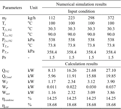
Table 3 show the theoretical analysis of thermal efficiencies of the system for the working fluid mass flow rate difference between 112kg/h to 372kg/h and the heat source temperature was 100°C. The theoretical work turbine results were between 1.16-3.86kW, whereas the experimental thermal efficiency for the temperature heat source is show in the Table 4. In the all case of heat source temperature were 100oC, the Rankine cycle efficiency was 14.25%.
These results imply that the pressure difference dominates the turbine torque and power. In other words, and appropriate working fluid that can maximize the pressure difference for a particular temperature difference should selected.
[image:4.612.317.570.168.528.2]Table 4 lists the maximum power output condition for temperature heat source were 96.1, 96.8, 95.6, and 96.8oC, the maximum turbine power were 1.60, 4.35, 12.50, and 15.73W, while the theoretical turbine power were 1.17, 2.34, 3.12, and 3.90kW, respectively. The thermal efficiency of system for the temperature heat source in the Table 4 are as follow, in the case of heat source temperature was 96.8oC the measure thermal efficiency was 0.019%, while the theoretical thermal efficiency was 16.52%. It can be seen that experimental thermal efficiency is very less than of the theoretical thermal efficiency.
Table 3
The results of the numerical simulation (Theoretical analysis)
Parameters Unit Numerical simulation results Input condition
mf kg/h 112 223 298 372
Ts
o
C 100 100 100 100
Tf,i,VG oC 30.3 30.3 30.3 30.3
Tf,o,VG oC 90.0 90.0 90.0 90.0
Pf,o,VG kPa 538 538 538 538
TT,o oC 73.8 73.8 73.8 73.8
PT,o kPa 358.4 358.4 358.4 358.4
Pr - 1.5 1.5 1.5 1.5
Calculation results
QVG kW 8.13 16.26 21.68 27.10
QCond kW 5.96 11.91 15.88 19.85
WT kW 1.17 2.34 3.12 3.90
WP kW 0.011 0.022 0.030 0.037
Wnet kW 1.16 2.32 3.09 3.86
rankine % 14.25 14.25 14.25 14.25
[image:4.612.319.569.169.521.2]cnt % 18.68 18.68 18.68 18.68
Table 4
The experimental results and performance of maximum power output condition
Parameter Unit Maximum Power Output Condition
mf kg/h 128.9 239.1 305.5 384.4
Ts oC 96.1 96.8 95.6 96.8
Tf,i,VG
o
C 31.8 30.7 33.4 31.7
Pf,o,VG kPa 478 484 398 397
Tf,o,VG oC 85.1 85.6 77.8 82.3
Qin,VG kW 8.41 15.78 17.33 23.73
Pr - 1.15 1.18 1.13 1.13
N rpm 573 946 1420 1369
N.mm 0.023 0.044 0.084 0.110
WT,max W 1.60 4.35 12.50 15.73
sys % 0.02 0.03 0.07 0.07
cnt % 14.8 15.1 13.2 14.2
0.00 0.25 0.50 0.75 1.00 1.25 1.50
0.0 1.0 2.0 3.0 4.0 5.0 6.0 7.0 8.0 9.0 10.0
60 70 80 90 100 110
W
o
rk
turbi
ne,
kW
Hea
t
ra
te
o
f
v
a
po
r
g
ener
a
to
r,
kW
Vapor generator temperature, oC HCFC-141b
m = 112 kg/h
Fig. 4 the effects of vapor generator temperature on the turbine inlet mass flow rate and the turbine output
Fig. 4 show the effects of vapor generator temperature (TVG) on the heat rate of vapor generator and the turbine
output on mass flow rate of working fluid of 112 kg/h, while the temperature heat source at the vapor generator is fixed at 70oC to 100oC. As for the case of TVG = 100oC, the
turbine output increases as the mass flow rate decreases. Conversely, it only slightly decreases in the case of TVG =
[image:4.612.44.294.487.711.2]International Journal of Emerging Technology and Advanced Engineering
Website: www.ijetae.com (ISSN 2250-2459, ISO 9001:2008 Certified Journal, Volume 4, Issue 1, January 2014)660
It is therefore understood that the turbine output decreases when the mass flow rate in the turbine inlet decreases rapidly. If a working fluid with a low latent heat is used, the saturated vapor at the turbine inlet would give the good operating conditions.
0.0 0.5 1.0 1.5 2.0 2.5 3.0
0 50 100 150 200 250 300 350 400
50 60 70 80 90 100
T
u
rb
in
e
ou
tp
u
t
[ k
W
]
M
as
s
fl
ow
r
ate
[ k
g/
h
]
Turbine inlet temperature [ oC ] HCFC - 141b
Pressure ratio 5
[image:5.612.50.283.202.344.2]Turbine inlet pressure 0.54 MPa
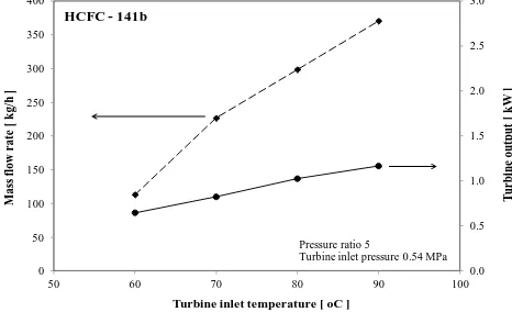
[image:5.612.324.566.258.415.2]Fig. 5 the effects of heat source temperature on the turbine inlet mass flow rate and the turbine output
Fig. 4 show the dependence of the turbine output on the temperature inlet temperature under the superheated vapor conditions at the turbine inlet temperature of vapor generator. In the case of each temperature heat source, the turbine output increases proportionally with the increase in the temperature heat source. These results can be understood as follows. The theoretical turbine efficiency will be increase as temperature heat source, turbine inlet temperature, pressure ratio, and only the mass flow rate increases proportionally as the compact vapor generator input increases. Accordingly the relationship between the turbine output and the temperature heat source is obviously expressed. These simulation results show that HCFC-141b gives the good performance, even though the system uses low temperature heat sources.
0.0 2.5 5.0 7.5 10.0 12.5 15.0 17.5 20.0
50 55 60 65 70 75 80 85 90 95 100
cyc
le
e
ffi
ci
en
cy
[ % ]
Turbine inlet temperature [ oC ]
Rankine cycle % Carnot cycle %
[image:5.612.325.563.446.604.2]HCFC - 141b
Fig. 6 Relationship between turbine inlet temperatures with cycle efficiency
Fig. 6 presents the dependency of the turbine inlet temperature on the cycle efficiency for turbine inlet temperature difference between 60°C to 90°C of HCFCs-141b. These results tell us the characteristics of each temperature heat source and the effect of the pressure ratio. The cycle efficiency of each turbine inlet temperature increases as pressure ratio rises, and working fluid has a good efficiency. Therefore raising the turbine inlet temperature, for the case of using HCFCs-141b give high system performance
0 50 100 150 200
0 500 1000 1500 2000 2500
T
urbi
ne
to
rque,
N
.m
m
Turbine rotation speed, RPM
Ts = 96.1C(128.9kg/h) Ts = 96.1C(239.1kg/h) Ts = 96.5C(305.5kg/h) Ts = 95.4C(384.4kg/h)
Fig. 7 Relationship between turbine torque and rotation speed in the
cases of average temperature heat source Ts between 95.4oC to 96.5oC
0 5 10 15 20
0 500 1000 1500 2000 2500
T
urbi
ne
Output,
W
Turbine rotation speed, RPM
Ts = 96.1C(128.9kg/h) Ts = 96.1C(239.1kg/h) Ts = 96.5C(305.5kg/h) Ts = 95.4C(384.4kg/h)
Fig. 8 Relationship between turbine output and rotation speed in the
cases of average temperature heat source between 95.4oC to 96.5oC
[image:5.612.55.287.554.689.2]International Journal of Emerging Technology and Advanced Engineering
Website: www.ijetae.com (ISSN 2250-2459, ISO 9001:2008 Certified Journal, Volume 4, Issue 1, January 2014)661
In the heat source temperature is 96.5oC the maximum torque and maximum power reached 169.12N.mm and 15.73W, respectively; similar results were obtained the all cases of temperature heat source. The maximum torque increment was caused by pressure difference pressure ratio between the turbine inlet and outlet in the case of small system
Fig. 9 shows relationship between turbine output and turbine torque dependence on the working fluid mass flow rate at a compact vapor generator under the superheated vapor at the turbine inlet. In the case of each working fluid mass flow rate, the turbine output increases proportionally with the increase in the vapor generator temperature input. These results can be described as follows, the turbine output is inlet temperature while set as pressure ratio are constant, and only the mass flow rate increases proportionally as the vapor generator input increases. Accordingly the relationship between the turbine output, turbine torque versus the working fluid mass flow rate under temperature heat source input range 95.6oC to 96.8oC are expressed as a linear straight line, however at different value of slopes. These experimental results tell us that working fluid gives the good performance, even though the ORC uses low temperature heat sources.
0 5 10 15 20
0 20 40 60 80 100 120
100 150 200 250 300 350 400
T
u
rb
in
e
ou
tp
u
t,
W
T
u
rb
in
e
tor
q
u
e, N.m
m
Working fluid mass flow rate, kg/h
[image:6.612.325.563.136.295.2]Torq (N.mm) PT,max (W)
Fig. 9 Relationship between working fluid mass flow rate, turbine torque and turbine output
0 100 200 300 400 500 600
75 78 81 84 87 90
V
ap
or
ge
n
er
at
or
p
re
ss
u
re
,
k
P
a
Vapor generator outlet temperature, oC
Ts=96.1C Ts=96.1C Ts=96.5C Ts=95.4C
Fig. 10 Relationship between temperature and pressure at the vapor generator
Fig. 10 shows the characteristics of temperature heat source and when the working fluid is HCFCs-141b. For fourth cases, there are optimum operating conditions in the relationship between the turbine output and the rotation speed. These optimum operating conditions shift to a higher rotation speed as the vapor generator input rises. In the case of a vapor generator temperature of 96.1oC, the maximum outlet pressure at the vapor generator is 483.9kPa. Whereas the temperature heat source at 76.9oC, the maximum outlet pressure at the vapor generator is 389.4kPa.
IV. CONCLUSION
[image:6.612.52.293.418.575.2]International Journal of Emerging Technology and Advanced Engineering
Website: www.ijetae.com (ISSN 2250-2459, ISO 9001:2008 Certified Journal, Volume 4, Issue 1, January 2014)662
In this study concluded that, at the heat source temperature between 95.4oC to 96.1°C and working fluid mass flow rate between 128.9kg/h to 384.4 kg/h were the measured turbine torque and turbine output of the system were between 28.7 to 109.7N.mm and 1.60 to 15.73W. The measured thermal system efficiency was 0.013% to 0.052%, while the theoretical thermal efficiency was 14.25%. These efficiencies are not high enough for realizing an actual system. The maximum turbine output was 15.73W in the case of temperature heat source was 96.8°C. A few pressure differences between the turbine inlet and outlet resulted in few turbine output.
Acknowledgment
The authors would like to thank the Graduate School, Faculty of Engineering, Chiang Mai University and Energy Policy and Planning Offices, Ministry of Energy for supporting the facilities and financial for this study.
Nomenclature
m Mass flow rate, kg/s W Work, kJ/kg Ρ Pressure, kPa T Temperature, °C W Work, kJ/kg Q Heat released, W
Torque, N.mm Pr Pressure ratio, -
Efficiency, %
Subscripts
c condenser vg vapor generator p pump
t turbine s heat source f working fluid th theoretical s heat source exp experiment i inlet
o outlet d diameter cnt carnot cycle sys system
REFERENCES
[1 ] S. Chaitep, S. Wongsiri. and N. Vorayos., (2006), Design and Development of Small Free Power Turbine, 3rd Aerospace Engineering Conference of Thailand, Kasetsart University, Bangkok, Thailand, March 17-18.
[2 ] Saleh, B. Koglbauer, G. Wendland, M. Fischer, J. (2007). Working fluids for low – temperature organic Rankine cycles. Energy J., 32, 1210-21.
[3 ] Maizza, V. Maizza, A. (1996). Working Fluids in Non-steady Flows for Waste Energy Recovery Systems. Applied Thermal Engineering J., 16(7), 579-90.
[4 ] Lui, B. Chien, K. Wang, C. (2004). Effect of working fluids on organic Rankine cycle for waste heat recovery”, Energy J., 29, 1207-17.
[5 ] Badr O, Probert S.D., O’Callaghan P.W., (1985), Selecting a workingfluid for aRankine cycle engine, Applied Energy J., 21(1), PP: 1–42.
[6 ] Lee M.J., Tien D.L., Shao C.T. (1993). Thermophysical Capability of Ozone Safe Working Fluids for an Organic Rankine Cycle System. Heat Recovery System & CHP J., 13, 409-18.
[7 ] Hung, T. C. (2001). Waste heat recovery of organic Rankine cycle using dry fluids. Energy Convers Manage J., 5, 539-53.
[8 ] Borsukiewicz – Gozdur, A., and Nowak, W., (2007), Maximising the working fluid flow as a way of increasing power output of geothermal power plant, Applied Thermal Engineering J., 27(11-12), PP: 2074–2078.
[9 ] [9] Lui, B., Chien, K., and Wang, C., (2004), Effect of working fluids on organic Rankine cycle for waste heat recovery, Energy J., 29(8), PP: 1207–1217.
[10 ]Wei, D., Lu, X., Lu, Z., and Gu, J., (2007), Performance analysis and optimization of organic Rankine cycle (ORC) for waste heat recovery, Energy Conversion and Management J., 48(4), PP: 1113– 1119.
[11 ]Chandramahan Somayaji, (2008), First and second law analysis of Organic Rankine cycle, Ph.D. Thesis, Mississippi State University, Mississippi, USA, 128 Pages.
[12 ]Saiai, P., Chaitep, S., Bundhurat, D., and Wattanawanyoo, P., (2013), Performance Assessment and Thermal Efficiency of a Compact Vaporizers Used in Low Pressure Turbine Cycle, the 2013 on International Conference of Alternative Energy in Developing Countries and Emerging Economies, May 30-31, Pullman Bangkok King Power Hotel, Bangkok, Thailand.
[13 ]Saiai, P., Chaitep, S., Bundhurat, D., and Wattanawanyoo, P., (2013), Performance Assessment and Thermal Efficiency of a Compact Vaporizers Used in Low Pressure Turbine Cycle, Energy Procedia, (2013), Published by Elsevier.
[14 ]Saiai, P., Chaitep, S., Bundhurat, D., Na Lampang, T., and Wattanawanyoo, P., (2013), Preliminary Design and Experimental Studies of Low Pressure Turbine for Organic Rankine Cycle Engine, National Conference on 12th Heat and Mass Transfer in Equipment
and Process, March, 14-15, Imperial Golden Triangle Resort Hotel, Chiang Rai, Thailand., PP: 275–280.
[15 ]Saiai, P., Chaitep, S., Bundhurat, D., and Wattanawanyoo, P., (2014), Design and Testing of Vapor Generator for Low Pressure Turbine, J. of Engineering and Technology, College of Engineering, Rungsit University, Thailand.
![Fig. 1 schematic diagram of organic Rankine cycle for numerical simulation [12-16]](https://thumb-us.123doks.com/thumbv2/123dok_us/8721087.884207/2.612.325.566.135.401/fig-schematic-diagram-organic-rankine-cycle-numerical-simulation.webp)