AUTOMATIC ADAPTIVE RECONFIGURABLE FPGA WITH
REUSABLE TECHINIQUES USING ARM
1C. SUBASHINI, 2Dr. UMA RAJARAM,3DR.S.RAVI
1,2
Dr. MGR Educational and Research Institute University, Chennai, INDIA
Email: 1subashini200235617@yahoo.co.in, 2umarajaram1@yahoo.com, 3 ravi_mls@yahoo.com
ABSTRACT
This papers discusses about reconfigurable system that allow online adaptation, whenever a fault occurs in the system. This is obtained by using FPGA that switches among Configurable Logic Block(CLB) automatically which has same features in an optimal manner. This reduces the time and complexity. Also the faulty CLB is tested for its output and if it matches with a desired output pattern, then it can be used instead of a spare so that the area efficiency improves. Automatic adaptation, selection of signals and controlling is obtained using ARM STM32 controller . Different modulation application is chosen to enumerate this reconfiguration by the controller.
Keyword: Field Programmable Gate Array (FPGA), Configurable Logic Blocks (CLB), ARM
1. INTRODUCTION
Fault tolerance is becoming an increasing important issue. Runtime reconfigurable hardware architecture have a power to balance fault tolerance with performance, allowing the amount of fault tolerance to be tuned at runtime [9,11], BIST can be designed to run on and take advantage of runtime reconfigurable architecture.
An analysis of the fault tolerance is achieved by an autonomous fully embedded evolvable hardware system [1] which uses a combination of partial dynamic reconfiguration and an evolutionary algorithm. It demonstrates the system that may self-recover from both transient and cumulative permanent faults [3,16]. Extra resource requirements are minimal and recovery time is also minimal.This paper shows that the integration of online testing in reconfigurable systems incurs only minimum impact on performance while delivering high fault coverage and low test latency. The algorithm provides multi resilience, model free coverage,autonomy, compartmentalized throughput and recovery [2] and also time and area efficiency for FPGA systems.In life-like behavior in respect to isolating faults, repairing faulty components and maintaining the pre-defined system goals is achieved [4]. Fault isolation using actual run time functional inputs is achieved.
The exhaustive testing procedures or resource intensive evaluation is also avoided.An area-efficient dynamic fault-handling approach achieves high survivability for DSP circuits [5,7]. Fault
detection, isolation, and recovery are performed using discrepancy information derived from the existing functional throughput by reconfiguring one of the N+1 Reconfigurable Partitions (RPs) to replicate each of the N modules in succession [15,18].
In the forth coming sections (2) the basic block diagram that explains about the experimental setup is discussed. Next in (3) the description of the proposed system is given. In section (4) the hardware features is enumerated. Section (5) gives the pin diagram of the setup that is to be implemented. In the section 6 the simulation results and future scope is discussed.
2. EXPLANATION
The basic idea is to develop a system to test online requirement using FPGA. For achieving this on line reconfiguration of the system should be done. Automatic recovery from fault should be done for better coverage of area.
The main concept here is on line adaptation and automatic fault tolerance. This is important to automatically configure the devices and to test for automatic selection of CLBs so that it can cover large volume of faults.
Fig. 1 Basic block diagram
The fault tolerance and selecting the core is done by using an application of selecting either ASK, FSK or BPSK modulation type [6]. First different modulation signals are generated using MAT lab. Then the pattern so obtained is fed to the reconfigurable controller, here ARM STM32 is used [10,13]. This selects the signals and bit file is created and thus, the bit file that is created is fed to FPGA.
The modulation recognizer constantly monitors the type of the modulation present in the input signal and generates distinct enable signals for ASK, FSK or BPSK modulation type. Each of the demodulator is equipped with a modulation recognizer at the front end so that can track the changes in the modulation of the input signal [12,14]. While the data is being demodulated the enable signals are read using the ARM. The ARM program keeps the state of the FPGA configuration as to what the current demodulator is. If the modulation changes the FPGA is reconfigured by downloading the appropriate bit file. So the ”Logic Core” can be either ASK, FSK or BPSK modulation type with a modulation recognizer hooked onto it.If the recognizer fails then the nearest spare CLB is identified and functionally and structurally mapped to continue operation.
2.2 Example
For example, let there be six CLB out of which three alone are configured and active. In case of fault, the nearest spare CLB has to be identified and mapped functionally and structurally to continue operation. (Refer Figure 2).
Fig. 2 FPGA State-1
When the first active CLB becomes faulty, the nearest spare PE is (row2, column1) is mapped
[image:2.595.309.505.552.634.2]along with the routing details, connectivity details and functional details. This is shown in Figure 3.
Fig.3 FPGA State-2
Now for example let us assume that the second active CLB becomes faulty then the nearest spare PE for this (row1, column 2) is mapped along with the routing details, connectivity details and functional details. This is shown in Figure 4.
Fig.4 FPGA State-3
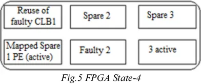
In the previous states when one CLB goes faulty, then its nearest spare is configured. For example, when we have many faulty CLB, instead of configuring the spares, we can find if there is any faulty CLB that gives the pattern or output that matches the output or pattern of any one of the CLB that is faulty and use that CLB. For example, in the state 3 it can be assumed that faulty 1 CLB gives that output that 2 active has to give then instead of using another spare we can reuse the faulty 1 CLB. Thus, the area or number of CLB used is reduced.
Fig.5 FPGA State-4
3. PROJECT DESCRIPTION
[image:2.595.97.260.617.700.2]3.1 Automatic FPGA Code Generation
[image:3.595.282.506.78.391.2]Using matlab different modulation signals using sysgen was generated. The output got here is .mdl file. This generates FPGA code for different modulation techniques automatically. Hence .ise file is got.
Fig. 6 Automatic FPGA code generation
3.2 Controller Generation
[image:3.595.99.279.204.271.2]STM32 ARM controller was used as controller for reconfiguring FPGA. This finds what was the input signal and corresponding pattern is generated and that is loaded in FPGA.
Fig. 7 Controller Generation
3.3 Top Module Implementation
.ise file created by matlab was given to FPGA for implementing the signal pattern; next the patterns are synthesized and checked. This was stored and its corresponding structure and configuration is stored in near CLB which is marked as its spare. This process is done for all the modulation signals.
Fig. 8 Downloading the bit file into FPGA and getting output in CRO
Then it is loaded in the Xilinx. For selecting what is the signal that is received Arm processor is used for controlling and comparing the signal received and only the respective signal is given to the FPGA. The transmission of signal and its output is viewed using CRO through FPGA.
During transmission if the path fails then the FPGA is configured such that the signal immediately takes the nearest path for transmitting the signal.Fault detection is an important step in guaranteeing the correct selection and transmission of the signal without any loss. Moreover, fault diagnosis is required. The selection of the nearest path can be done by using the configured spare CLB that is having the same configuration. The main part is selecting the correct CLB.
4. HARDWARE AND SOFTWARE
REQUIREMENTS 4.1 Features of STM32
STM32 was used as the controller. The features of STM32 are,
• 32-bit RISC processor
[image:3.595.92.291.377.470.2]• LCD parallel interface
• Nested vectored interrupt controller • I²C bus
• USART
• Serial peripheral interface
• Inter-integrated sound • SDIO
• Controller area network • Universal serial bus
• GPIOs • ADC • DAC
• Serial wire JTAG debug port • Embedded Trace Macrocell
Fig.9 STM32 ARM kit
4.2FPGA Used Reconfiguration
Spartan 3was used as reconfiguration
core.VHDL was the software used.
5. CONNECTION BETWEEN ARM AND FPGA
The above circuit diagram shows the
interconnection between ARM and FPGA.
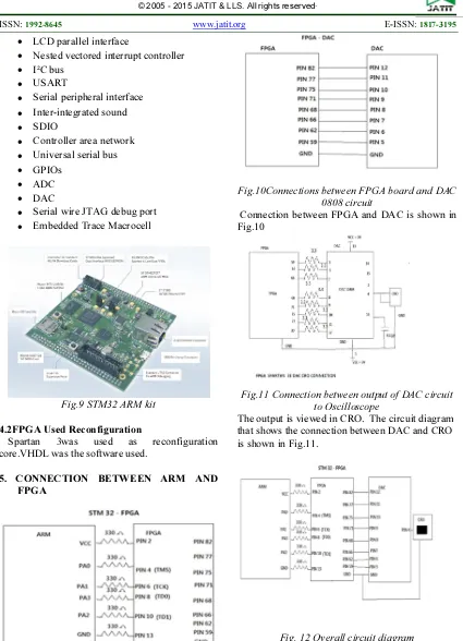
Fig.10Connections between FPGA board and DAC 0808 circuit
[image:4.595.89.514.95.683.2]Connection between FPGA and DAC is shown in Fig.10
Fig.11 Connection between output of DAC circuit to Oscilloscope
[image:4.595.89.467.518.734.2]The output is viewed in CRO. The circuit diagram that shows the connection between DAC and CRO is shown in Fig.11.
6. RESULTS AND DISCUSSION
[image:5.595.88.292.206.332.2]The output waveforms of the modulated waves are shown in the following figures Fig.13, Fig.14, Fig.15, Fig.16. that are reconfigured.
Fig. 13 Downsampler Waveform
Fig. 14 Output Waveform Of ASK Signal
Fig. 15 Output Waveform Of FSK Signal
Fig. 16 Output Waveform Of BPSK Signal
7. CONCLUSION
The capabilities offered by the re-configurable platform have been demonstrated which can be a promising choice.The faulty cores were mapped and reconfigured in FPGA automatically. The bit files or configuration word are stored in ARM which is the controller and matlab .mdl files are created and converted to .ise file and dumped in FPGA using sysgen automatically. Thus , providing reconfiguring the FPGA. This has helped to reduce time, cost and area of usage. This is demonstrated using different modulation signls. This shown by simulation. The future scope is to implement in hardware. Also to calculate the energy needed, and to do spectral analysis.
REFERENCES:
[1] Lars Bauer, “Test Strategies for Reliable Runtime Reconfigurable Architectures”, IEEEtransactions on computers, Vol. 62, No. 8, August 2013.
[2] Naveed Imran, “Amorphous Slack Methodologyfor Autonomous Fault-Handling in Reconfigurable Devices”, International Journalof Multimedia and Ubiquitous Engineering, Vol. 7, No. 4, October 2012.
[3] Carthik A. Sharma, “Self-healing reconfigurable logic using autonomous grouptesting”, Microprocessors and Microsystems 37, pp. 174–184, 2013.
[4] Naveed Imran, “Fault-Mitigation by Adaptive Dynamic Reconfiguration for Survivable Signal-Processing Architectures”,International Journalof Control and Automation Vol. 6, No. 2, April 2013.
[5] P.Prakasam, M.Madheswaran,
[6] Rajib Das, “FPGA Implementation of DigitalModulation Schemes: BPSK and QPSK Using VHDL”, IJECT, Vol. 5, Issue2, Jan.– March2014.
[7] B.Harikrishna and S.Ravi, “Autonomous Self-Healing of Reconfigurable Circuits”, Indian Journal of Research, Vol. 2, Issue9, Sept. 2013.
[8] Molabanti Praveen Kumar, T.S.R Krishna Prasad, M.Vijaya Kumar, “Implementation of Digital CommunicationLaboratory on FPGA”, International Journal of Advanced Research in Computer and Communication Engineering, Vol. 2, Issue 11, November 2013.
[9] Wang Lie, Wu Feng-yan, “Dynamic partial reconfiguration in FPGAs”, Third International Symposium on Intelligent Information Technology Application, IEEE Computer Society, 2009.
[10]Khoa Dang Pham, Abhishek Kumar Jain, Jin Cui, Suhaib A. Fahmy, Douglas L. Maskell, “Microkernel Hypervisor for aHybrid ARM-FPGA Platform”, ASAP, IEEE, 2013.
[11]M. Hubner, D. Gohringer, J. Noguera and J. Becker, “Fast dynamic andpartial reconfiguration data path with low hardware overhead on XilinxFPGAs”, in IEEE International Symposium on Parallel DistributedProcessing, Workshops and Ph.D. Forum (IPDPSW), pp. 1–8, 2010.
[12]H. So, A. Tkachenko and R. Brodersen, “A unified hardware/softwareruntime environment for FPGA-based reconfigurable
computers using BORPH”, in
Hardware/Software Co-design and System Synthesis(CODES+ISSS), pp. 259–264, 2006. [13]M. Hubner, P. Figuli, R. Girardey, D. Soudris,
K. Siozios, and J. Becker,“A heterogeneous multicore system on chip with run-time reconfigurable virtual FPGA architecture” IEEE International Symposiumon Parallel and Distributed Processing Workshops (IPDPSW), 2011.
[14]P. Sedcole, B. Blodget, T. Becker, J. Anderson and P. Lysaght, “Modular dynamic reconfiguration in Virtex FPGAs”, Field Programmable Logic and Applications, IEE Proceeding Computer Digital Technology, Vol. 153, No. 3, May 2006.
[15]Steiger, C., Walder, H., and Platzner, M., “Heuristics for onlinescheduling real-time tasks to partially reconfigurable devices”, Field-Programmable Logic and Applications, (Springer-Verlag), pp. 575–58, September 2003.
[16]Blodget, B., James-Roxby, P., Keller, E., McMillan, S. andSundararajan, P., “A self-reconfiguring platform”, Field-Programmable Logic and Applications, (Springer-Verlag), pp. 565–574, September 2003.
[17]Huebner, M., Becker, T., and Becker, J.: “Real-time LUT-basednetwork topologies for dynamic and partial FPGAself-reconfiguration”, Symposium on Integrated Circuits and SystemsDesign, ACM, pp. 28–32, 2004.