ANALOG COMPUTER STUDY OF A SEMI-BATCH REACTOR
INTRODUCTION: This paper considers a reactor design application of the PACE® TR-48 General Purpose Analog Computer, viz: the chlorina-tion of benzene in a semi-batch reactor. The major objective of the
study will be to relate the maximum production of intermediate chloro-benzenes to the chlorine feed rate and the time of reaction. Another objective consists of illustrating how experimental kinetic data can be fitted on such a computer to obtain reaction rate constants.
Since the majority of both inorganic and organic chemical products of the chemical industry are formed by one or more chemical reactions, the chemical engineer is continually faced with the problem of designing flow, batch, or semi-batch reactors. In recent years, the cost of design-ing and optimizing a reactor has been sharply reduced through the use of the general purpose analog computer. The computer is used to simulate the behavior of the process in question. Proposed changes in the process and its eventual optimization can then be accomplished quickly, and with-out expensive equipment modifications.
THE PHYSICAL SYSTEM
The chlorination of benzene (C 6H6) produces monochlorobenzene (C 6H5Cl), dichlorobenzene (C6H4CI2), and trichlorobenzene (C6H3CI3) through successive, competing chemical reactions:
HCI, EXCESS Cl z
C
6H6 + CI2 - - . C6H5CI + HCI (1) C
6H5C1 + C12 ----.C6H4C12 + HC1 (2) C
6H4C12 + C12 - - . C6H3C13 + HCI (3)
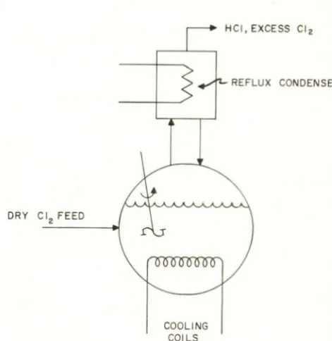
These reactions are carried out in a lead-lined or iron vessel, which is shown in Figure 1, with ferric chloride (FeCl3) as a catalyst. The vessel is fitted wi th cooling coils, since the chlorination reactions are exothermic, and a reflux condenser. The pur-pose of the reflux condenser is to return vaporized chlorobenzenes to the system, while allowing the hydrogen chloride and excess chlorine vapor to leave the system. In order to maintain the react-ing mixture at a uniform temperature and to mini-mize mass-transfer effects, the reacting mixture is well agitated.
Printed in U.S.A. 113
1
DRY Clz FEED
COOLING COILS
[image:1.614.333.569.394.636.2]REFLUX CONDENSER
Figure 1. Semi-Batch Reactor Diagram No chlorobenzenes can be formed until some ofthe chlorine gas, which is being bubbled through the liquid benzene, has gone into solution. The amount of chlorine which is capable of going into solution
@Electronic Associates, Inc. 1963 All Rights Reserved
is limited by the solubility of chlorine in the react-ing mixture, which depends on the operatreact-ingcondi- operatingcondi-tions of the reactor, Since the chlorobenzenes are formed successively, the concentrations of mono-and dichlorobenzene will each pass through a def-inite maximum at some time during the process, Eventually, all of the benzene will have reacted to pure trichlorobenzene (and other chloro-hydrocar-bons, which have been neglected),
The following restrictions can be made on the system:
(1) No liquid or vapor hold-up occurs in the reflux condenser,
(2) The system operates under isothermic and isobaric conditions,
(3) Changes in the volume of the reacting mix-ture are negligible,
(4) Hydrogen chloride gas vaporizes and leaves the system,
(5) Negligible mass transfer resistance occurs between the gaseous chlorine and the chlo-rine in solution (up to solubility limit of chlorine),
THE MATHEMATICAL MODEL
The equations defining the reaction kinetics of the system, given in several references (2,5), are
v
(4)(5)
(6)
(7)
where
v
Volume of reacting mixturet Time
N(t) Moles per unit volume
k Rate constant in volume per unit mole per unit time,
and the subscripts represent the following:
C Chlorine
M Monochlorobenzene
D Dichlorobenzene
T Trichlorobenzene
B Benzene
1 Rea c t ion producing monochloroben-zene
2 =: Reaction producing dichlorobenzene
3, =: Reaction producing trichlorobenzene
These equations have the initial conditions:
NB(O) =: N
0 (8A)
NC(O) 0 (8B)
NM(O) 0 (8C)
ND(O) 0 (8D)
NT(O) 0 (8E)
Equations 4-7 can be added and integrated to ob-tain the benzene material balance equation
If the mass transfer effect of chlorine being trans-ferred from the vapor to the liquid phase is ne-glected, the chlorine concentration in the system is described by the material balance equation
t
NC(t)
=
Jr
dt x(t) (10)LV-'
~
'----y--l
moles of moles of moles of chlorine in chlorine chlorine solution supplied reacted
(in terms of the chlorobenzene concentrations) from the stoichiometry of the system, namely
(11)
The solubility of chlorine in the reacting mixture was obtained by considering the total pressure above the liquid, 7f, which is equal to the sum of the
par-tial pressures, p, of the inidividual components in the vapor phase. Thus
(12)
Since its tenure in the system is only momentary, the partial pressure of hydrogen chloride was ne-glected. * By applying Raoult's Law, which states that the partial pressure is equal to the product of
. N(t)
the mole fractlOn, NO + NC (t)' and the vapor
pressure, po, equation 12 becomes
This equation can be solved for the maximum chlorine concentration, NC (t), to obtain
(14)
NT ( t)
0]
- NO PT
Since the vapor pressures are functions of tem-perature only and the system is isothermal and isobaric, the maximum chlorine concentration de-pends only on the chlorobenzene concentrations. Any excess chlorine supplied to the system leaves it through the reflux condenser.
A more convenient form** of the system equations may be obtained by defining
k NO
h=-V-8
=
h t*System operated above critical temperature of HCl.
(15)
(16)
**The equations were written in terms of 6,
H,
and ~ because experi~ mental data was avai lable on the ratios of the rate constants; and kl was unknown.3
8 (8 )= N8( 8) I NO
M(8 )=NM( 8) I NO
0(8)= NOW) INO
T(8)=Nr( 8) INO
x
(8)=
X (8) I NO(17) (18) (19) (20) (21) (22) (23)
Using these definitions, equations 4 - 7, 9 and 11 become
d ~(:) = _ 8(8) C( 8)
(24)
d M ( 8 )
=
8( 8) C ( 8 ) - [ k 2 ] M ( 8) C (8 )d8 kl (25)
dO(8)
[k21
[k3]
d 9
= TrJ
M(8)C(8)-k7"
0(8)C(8) (26)dT(8) =
[~]
0(8)C(8) (27) d8 kl1= 8(8) +M(8) +0(8) +T(8) (28)
X(8) = M(8) + 20(8) +3T(8) (29)
Equation 10 can now be represented as
C (8 ) =
Ih
d8 - X ( 8 ) o(30)
which can be differentiated to obtain
dC(8) d X(8) = G
-d8 d8 (31)
or, by substituting
d~~8) =G-[B(8)C(8)+(:~) M(8)C(8)+(~~){32)
0(8)C(8)]
Equation 32 is the best form of the chlorine con-centration equation for computational purposes.
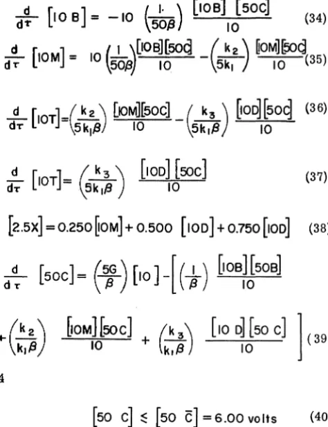
this system (4)--and 2 absolute atmospheres--which was assumed. Based on these operating conditions, the saturation concentration of chlor-ine, C(8), can be assumed constant and equal to 0.120. The proof ofthis fact is shown in Appendix A. This means that the constraint on equation 32 is
C(8)~
C
= 0.120 (33)PROGRAMMING THE COMPUTER***
This problem, which was solved on a ±10 volt PACE®, TR-10 General Purpose Analog Com-puter, presents no magnitude scaling problems. From the stoichiometry of the system it is obvious that B(8), M(e), D(e), and T(e) cannot exceed unity and that X(O) cannot exceed three. The chlorine concentration, C(8), is limited to 0.120; therefore its maximum value is obvious. These maximum values and their associated scale factors and com-puter voltages are tabulated in Table I. Table II lists the systems parametric data.
TABLE I. MAGNITUDE SCALING
Physical Estimated Scale Factor Computer Variable Maximum Value Volts Per Variable (Dimensionless) (Dimensionless) Dim. Unit (Volts)
B 1.0 10 [10 B]
M 1.0 10 [10 M]
D 1.0 10 [10 D]
T 1.0 10 [10 Tl
X 3.0< 4.0 2.5 [2.5 X]
C 0.12< 0.2 50 [50
c]
TABLE II. PARAMETER DATA
k
_2 = 0125(2)
k . 1
k
k3 =0.00417(2) 1
Dimensionless
Dimensionless
o
:$G:$0.008 (ASSUMED) Dimensionless***It is assumed that the reader is familiar with fundamentals of onalog computer programming.
The scaled voltage equations, which are based on the information contained in Tables I and II, are
d [10 B] = -10
f._
I_. ) [lOB] [50C] (34)dT \50,9 10
d [ . ]
f.
I \[IOB][50Q(k2 \
~OM][50q
~ 10M = 10 \50{3) 10 -\~) 10 (35)
d~ [IOT]=~:I~)
(37)[2.5X] = 0.250
~OM]
+
0.500 [100]+
0.750 [100] (38)4
[50 C]
~
[50C]
=6.00 volts (40)where machine time, T, is defined in terms of the
time scale factor {3, and 8 as
t' =,98 (41)
The computer diagram implementing these equa-tions is shown in Figure 2 and the components used are summarized in Appendix C. Potentiometer and amplifier assignments are tabulated in Tables III and IV. The time scale factor chosen for this problem was 0.05 (seconds of machine time per dimensionless unit). This choice was based on the fact that the feedback to the integrators had to be attenuated by responsible potentiometer settings in order to run the problem in a reasonable length of computer time (20 £: T £: 100 seconds).
When fitting experimental data to determine rate constants, it is advantageous to plot the results in time, t, rather than in the dimensionless variable, 8, since the kinetic data will be in terms of time. Time, which is related to 8 by equation 16, can be obtained from the equation
dt I
[image:4.615.308.545.84.392.2]+10
10
-10
FSI
101.1
9 >..;..:O..;.T _ _ _ -{ SOC
TPI
"16~
, 1
-SOC''''':
o
'"
/
,
:~
:
-50C ~
1, •
SOMC 51.13
- 0 '
~---~12~-~2~.5~X~---~1 14~~2~ .. 5~)(~
5SC 51<, OC
+
-fJ {.JII,
+10 0.500
r---~---{~--~14
-10 0.375 ~-+---l<1 12
10
ON
'>---¢---b-o FS2
50C
UP
SOC
-10
-~
0.010 [0.1T]
OR OR
V j}
[~tLt]"
k,NofJtL
<> ANALYSIS OF 1(1 NETIC DATA FOR RATE CONSTANTS
Figure 2. Computer Diagram
TPI
[image:5.793.69.750.103.511.2]TABLE
m
ELECTRONIC ASSOCIATES INC. EDUCATION
a
TRAINING GROUPTR-IO POTENTIOMETER ASSIGNMENT SHEET
PROBLEM
S~.~~
Ro.~
DATE _ _ _ _ _ _
SETTING STATIC SETTING POT PARAMETER CHECK
NO. DESCRIPTION STATIC OUTPUT RUN NOTES CHECK VOLTAGE NUMBER I
I
Cof-.)!.-y", .. n- cot.
V/~*
N"
-tLf>
o.
OJ 02
'/ld;;o(3
O. I <DO 0.4-003 Co~<;"TAt-..JT O,r;:;OC!
4
{'alsfe,~
o. r;-DO
===.-'--.'---5 Cot0'f.T A t01 c.SCO
6
-k3/S~,
f3
<0. ':;00 0.0117
C-e
Nc;:r-{l.t-3T
O,SOO8
Co
t-J
5.\i\
t-J \
():I~O9 CDt0~lA.
tJI
o.2.C;:D10
S:6/f3
0.\ 0 0 0 . 0 0 0II
Co
f-j $!~101
(0.<00012
L/
tv\IT
0.-.::sIS""
Af'F~i<-lkAIE13
14
L
I fv\ iT <0.s;-oo
~ t\J'P~O.K-11-t AlE15
16
17
18
19
20
21
22
23
fS 1
v..'P
J)l}24
FS
"2-
uP
U?
bt0
M673
6
POT NO.
I
2
3
4
5
6
7
8
9
10
II
12
13
14
15
16
17
18
19
20
21
22
23
Al'.1P NO.
I
2
a
4
5
G
7
8
9
10
II
12
13
14
15
16
11
113
19
20
TABLE IV
ELECTRONIC ASSOCIATES INC EDUCATION
e
TRAINING GROUPTR-IO AMPLIFIER ASSIGNMEN SHEET
PROBLEM
~.- ~
R.a.~
DATIE __________ __
OUTPUT STATIC CHECK
FB VARIABLE CALCULATED MEASURED
',~~lWI1§'J8n OUTPUT 1\I];'tGjl~~'C? OUTPUT
I
"l:/10
e'I..oot/t~
O.IOt
\0. cOOI
~\OBto
.co
t -\0.00~~
- S-oB.C
-to.oo
S
loB
\ 0 . 0 0I
10M4.
t;;ot
S.oo
I
-
\0])
-3,0(')i
£;,,00S
-
10M-S".oo
S
loD
- t;:,(DOI
IDT
-I,~Dt
\0.00I
SoC
-"3.00 A» lO.OCt-\~
S'oMC
~.ooS
-2.£;'")(- 6.'2£"'
I-\G
- SO
'be
~.ooS
'2.5"X
to.~~S
t;;o
C
<0.00S
-S'oC
to.oo
$
£BC/(1
+s
&"
bC
/~'f'
'2..'3s
'*
j\.f>J
i'<L ... , SI S ofK
I i\.lE"'f\c J:>A'TA fpI:!
'RA-,E
Co~->-r; i'tJrSt
IDOK FeE't>~A~ IN c...~Ec..K NA'PUf ~fHlI-FeE'bSi\oCk I~ C.I"E'~ AMI>LlF
~
10K
M6S9
7
NOTES
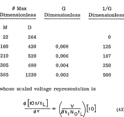
TABLE V. TIME OF MAXIMUM PRODUCTION VERSUS CHLORINE FLOWRATE
DATA
8 Max Dimensionless
M D
22 264
160 430
210 520
305 680
585 1230
G Dimensionless 0.008 0.006 0.004 0.002 I/G Dimensionless 0 125 167 250 500
whose scaled voltage representation is
d [IOUtLJ
-
~kl ~
0 tL) [101
dT (43)
The symbol tL is the maximum time required for the data analysis, and depends on the data being fitted.
A dynamic check of the computer circuit was made after completion of successful static check. The dynamic check consisted of checking the maximum concentration of monochlorobenzene and the time at which the maximum occurred, against the com-puter results for a special case of reactor opera-tion. The special case (FSI - DN, FS2- UP) assumes that the chlorine flow rate is infinite and that the reaction mixture is always saturated with chlorine. Calculations made on this basis indicate the maxi-mum value of M(O) will be 0.74 when 0 is 22 (Refer to Appendix B).
RESULTS
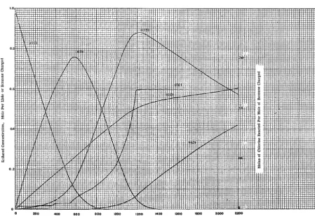
In addition to the dynamic check run, as shown in Figure 3, four additional runs were made at values of G ranging from 0.002 to 0.008. These results, which are plots of B(O), M(O), D(O), T(O), X(e) and
C(e) versus e, are shown in Figures 4-7. From this information, it was possible to obtain the values of 8, 0 max at which the maximum amount of
8
the intermediate products was present in the sys-tem. This data and the corresponding values of the flow rate variable, G, are tabulated in Table V. A plot of log {} max versus l/G is shown in Figure 8 for each of the intermediate products.
Figure 9, which is a plot of B(t), M(t), D(t) , and T(t) versus time for three values of k3/kl' serves to illustrate how experimental data can be fitted using the analog computer. By varying the reaction rate constants, which are unknown, the computer solution can be made to coincide with the experi-mental results to obtain these constants.
When this trial and error process is performed in real time, using an X- Y plotter, it is quite time-consuming. However, when high speed repetitive operation, which yields up to 60 solutions per sec-ond, is used in conjlL.'1ction with an oscilloscope, a transparent overlay of the experimentaldatacan be fitted in a matter of minutes, due to the fact that the effect of parameter variations on computer results can be observed instantly on the high per-sistence scope.
CONCLUSIONS
From Figure 3-7 it is obvious that the maximum reduced concentration of the intermediates is inde-pendent of the chlorine flow rate. These maximums, which occur at 0.74 and 0.88, can only be altered by changes in the reaction rate constants. This can be verified by consulting Figure 9. The chlorine feed rate, which controls the amount of chlorine available for reaction, affects the time at which the maximum concentrations occur. As shown in Figure 8, when the chlorine flow rate is infinite (l/G = 0) and the reaction mixture is always satur-ated with chlorine, {} max has its minimum values of 22 and 264. When the chlorine feed rate is re-duced, {} max increases. Obviously, if the feed rate of chlorine is zero (I/G-oo), {} must be infinite.
max
[image:8.621.37.276.77.302.2]1.0
'" "
~ u
~
~
"'
'0 oS
:3 " '" "
~
f
§ §
u '" 0 0.21
.g
~ t
o 40 00 .20 .00 000 :2:40 2C<l :00 400 440 400
Dimensionless Time, 0
Figure 3. Reduced Concentrations Versus Dimensionless Time For Infinite Chlorine Feed Rate
0.0
'" 0
~
t'l
'li
11 l':'
~ .!!
Ci u
0.' ~
~
Ci ~" '0
0
~
..
"0
"
::l 0
0.
t
OA N ~~ tll
0
§ f
u ~
'" ~ u
'0
TI -a
.
0.2 ::l
o
o 200 400 000 000 1000 ':000 1400 1000 '000 2000
Dimensionleas"Tlme,O
Figure 4. Reduced Concentrations Versus Dimensionless Time (G = 2. OxlO-3)
[image:9.623.87.555.36.345.2] [image:9.623.104.554.389.697.2]}
u
~
i
'a 0.0
0
~
" 0
..
.
~
S 0.4I
Su
al
~
0:
o.
200 400 000 000 1000 1200
Dimensionless Time, 8
Figure 5. Reduced Concentrations Versus Dimensionless Time (G
=
4. Ox10- 3)1.0
o o
-400
-
000 1000 1200Dimensionless Time, 8
Figure 6. Reduced Concentrations Versus Dimensionless Time (G=6. Ox10- 3)
[image:10.626.56.510.38.343.2] [image:10.626.56.513.389.700.2]200 400
Dimensionless Time, 8
Figure 7. Reduced Concentration Versus Dimensionless Time (G
=
8. OxlO- 3)A 01 CHLOROBENZENE
Reciprocal Chlorine Flow Rates, G-1
Figure 8. Dimensionless Time of Maximum Mono-and Dichlorobenzene Production Versus Reciprocal Chlorine Flow Rate
[image:11.620.92.549.36.340.2] [image:11.620.176.467.401.688.2]al
btl
..
01 .<:: U'"
s::'"
..
s::
!
'a~
~
..
'"
III
Ul
~
s::".~
':;j
..
1:'"
t>
s::
0
U
"5l
t>
"
~
1.0'0.9
0.8
o.r
0.6
0.5
0.4
0.3
0.2
0.1
o o
.01
c-;(
M
0 BENZENE
f1 MONOCHLOROBENZENE
0 DICHLOROBENZENE
0 TRICHLOROBENZENE
10 20 :so 40 50 60
Time, Minutes
[image:12.798.52.710.79.539.2]APPENDIX A
SOLUBILITY CONSTRAINT CALCULATIONS
The vapor pressure data at the 55 deg. C operating temperature, necessary to solve the equation
c (
t)=
---=-o-_-7T-Pc
is tabulated in Table VI.
]
TABLE VI. VAPOR PRESSURE DATA AT 55 C
Data Component Vapor Pressure Source
Benzene 327 mm of HG 3
Monochlorobenzene 48.8 mm of HG 3
Dichorobenzene 11.5 mm of HG 3
Trichlorobenzene <5 mm of HG 3
Chlorine 16.9 ATM 1
(A-1)
If this data is substituted into equation A-I, it can be seen that for all practical purposes since the total pressure is two atmospheres (see Table II), and the concentration variables cannot exceed unity. Based on equation A-2 the range of C(t) is
C (
t ) (A-2)0.105<
C(
t) < 0.134 (A-3)which is very narrow; therefore, variations in C(t) will have little effect on the results of the problem. The average value of C(t), 0.120, was considered sufficiently accurate for this study.
[image:13.621.213.447.328.445.2]APPENDIX B
DYNAMIC CHECK CALCULATIONS
If the reacting mixture is always saturated with chlorine, the equations describing the behavior of mono-chlorobenzene and benzene are
and
where
These equations have the initial conditions
and
The solution to equation B-1 is
dB
df
(e) = - B{e)B (O)
=
M{O)= 0=
Ii-e
which can be substituted into equation B-2 to obtain
whose solution is
M{O=
The maximum concentration of M(~) occurs when
where ~ , is the value of the argument at which the maximum occurs . . .
e'
=--k:-2-
--r;-This may be substituted back into equation B-8 to obtain the maximum value of M( ~ )
k21 kl
I (k2 ) l-k2/kl
M(e)=
-k.
kSince.2. is one-eighth (see Table II) and C is 0.12 (see Appendix A)
k1
M(el
=
O. 74and 8'= ~=
e-
22C
14
(B-1)
(B-2)
(B-3)
(B-4)
(B-5)
(B-6)
(B-7)
(B-8)
(B-9)
(B-lO)
(B-ll)
(B-12)
APPENDIX C
EQUIPMENT REQUIRED TO PERFORM SIMULATION
The equipment required to perform this simulation was:
1 -
x-
Y Plotter
and
3 - Quarter Square Multipliers
17 - Operational Amplifiers
6 - Integrator Networks
13 - Potentiometers
2 - Function Switches
NOMENCLATURE
B
=
Reduced Benzene concentration, dimension-lessC = Reduced Chlorine concentration, dimension-less
C = Reduced Maximum Chlorine concentration, dimensionless
D = Reduced Dichlorobenzene concentration, di-mensionless
G = Modified chlorine flowrate, dimensionless
M
=
Reduced Monochlorobenzene concentration, dimensionlessN = Concentration variable, moles
NC = Maximum chlorine concentration, moles
T
=
Reduced trichlorobenzene concentration, di-mensionlessv =
Volume of reacting mixture, cubic feetX
=
Reduced reacted chlorine variable, dimen-sionlessh = Modified rate constant, seconds-l
k
=
Reaction rate constant, cubic feet/mole sec-ondp
=
Partial pressure, atmospherespo = Vapor pressure, atmospheres
r
=
Chlorine feed rate, moles/ secondt = Time, seconds
tL = Maximum time, seconds
x
=
Moles of chlorine reacted7r
=
Absolute pressure, atmospheres(J = Dimensionless time variable, dimensionless T = Machine time, seconds
{3
=
Time scale factor, seconds/dimensionless unit~ = Dimensionless time variable, dimensionless
SUBSCRIPTS
B
=
BenzeneC
=
ChlorineD
=
DichlorobenzeneM
=
Monochlorobenzeneo
= Initial ValueT = Trichlorobenzene
1
=
Reaction producing Monochlorobenzene2 = Reaction producing Dichlorobenzene
3
=
Reaction producing TrichlorobenzeneREFERENCES
1. Perry, J.H., Chemical Engineers Handbook; pg. 150; 3rd Ed.; McGraw-Hill Book Co., Inc., New York, N.Y. (1950)
2. MacMullin, R.B., Distribution Reaction Products in Benzene Chlori-nations; Chern. Eng. Prog: 44; 183 (1948)
3. Lange, N.A., Handbook of Chemistry; pg. 962; Handbook Publishers, Inc., Sandusky, Ohio (1934)
4. Shreve, R.N., The Chemical Process Industries; 1st Ed.; pg. 851; McGraw-Hill Book Co., Inc., New York, N.Y. (1945)
5. Smith, J.M., Chemical Engineering Kinetics; pg. 62; McGraw-Hill Co., Inc., New York, N. Y. (1956)