EVALUATION OF STATCOM FOR GRID CONNECTED PV
SYSTEM
1 R.GANESH, 2 DR. V. SENTHIL KUMAR
1
Assistant Executive Engineer R&D TANGEDCO, Chennai, Tamilnadu, India
2
Associate Professor, Department of Electrical and Electronics Engineering, College of Engineering Guindy, Anna University, Chennai, Tamilnadu, India
E-mail: [email protected]
ABSTRACT
Demand in electricity makes the passion for renewable energy. The renewable energy can be effectively utilized when it is grid connected. In this paper Photo Voltaic (PV) power system is proposed for grid connected applications. Important factors to be considered in grid connection are quality of power, stability of the voltage and reliability. The quality and stability of voltage in a grid connected PV system can be improved by a STATCOM. Many researchers analyzed the performance of STATCOM with
balanced grid voltage dips. Under unbalanced grid voltage dips, the negative sequence voltage causes
poor power quality of power. In this paper, grid connected PV system with a STATCOM is proposed with
balanced and unbalanced voltage sags and swells. The positive and the negative sequence voltage
compensation by a STATCOM is proposed to improve the stability and quality of voltage. The entire system is analyzed by simulation using MATLAB/ Simulink.
Keywords: Photo Voltaic (PV) system, STATCOM, Incremental conductance Maximum Power Point Tracking (MPPT), balanced/unbalanced load.
1. INTRODUCTION
In the past decades, enormous amount of natural resources has been unlimitedly dissipated and our living environment has been severely polluted [1]. With increasing concern of global warming and the depletion of fossil fuel reserves, many are looking at sustainable energy solutions to preserve the earth for the future generations. Other than hydro power, wind and photovoltaic energy holds the most potential to meet our energy demands. Alone, wind energy is capable of supplying large amounts of power, but its presence is highly unpredictable. The technical and operational characteristics of wind-diesel hybrid systems are found various disadvantages like power generation only in remote areas, the high cost for its complicated and heavy mechanism of gears.
The other vital renewable energy is the solar energy presents throughout the day. It has emerged in the last decades since it has the aforesaid advantages and less maintenance, no wear and tear. The main applications of PV systems are either stand-alone systems such as water pumping, domestic and street lighting, electric vehicles,
military and space applications or grid-connected configurations like hybrid systems and power plants.
Safety is one of the major concerns in PV systems due to unintended is landing at the time of fault occurrence at the grid side. Here, PV systems continue to feed the load even after the network is disconnected from the utility grid, which may lead to electric shock of workers. PV systems usually are designed to operate near unity power factor to fully utilize solar energy. In this case, the PV system only injects active power into the utility grid, which may change the reactive power flow of the system. Therefore, voltages of nearby buses can be increased because of the lack of reactive power. The over-voltage produced by the PV system can have negative effects on the operation of both the utility and customer sides. Power fluctuation may cause power swings in lines, over- and under loadings, unacceptable voltage fluctuations, and voltage flickers [2].
All these investigations have covered,
balanced grid faults, but the majority of grid
faults is of the unbalanced nature. The unbalanced
voltage can cause many problems like unbalanced
torque, leading to mechanical vibration and
additional acoustic noise [3]. The STATCOM
control structure can be adapted to these
unbalanced-voltage conditions [4], and the positive
and the negative sequence of the voltage can be
controlled independently. Different current
injection methods based on symmetrical
components can also be applied to the STATCOM,
resulting in different output-power distributions
[5], [6]. This paper proposes the integration of STATCOM with the grid connected PV system for voltage control during balanced and unbalanced change in load.
2. PV POWER SYSTEM
The analyzed PV system consists of PV panels and DC-DC converter controller using MPPT technique.
2.1 PV Panel
The PV cell generates DC electricity whenever it is subjected to sunlight. Solar radiation sustains all forms of life on earth.
According to estimates, the sun radiates 1.74 x 10 17
W of power per hour to earth the daily solar energy
radiation varies from 4-7 kWh per and there are
[image:2.595.89.288.497.593.2]270-300 sunny days in a year. Generated power in the single PV cell is very less. For practical applications many PV cells are interconnected. Number of cells in series decides the voltage and the number of cells in parallel decides the current [7].
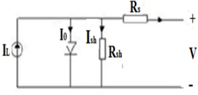
Figure 1: Equivalent Circuit of Solar Panel
The following parameters were used in the calculation of the net current of a PV cell.
Saturation current of the diode, Io, Net current from
the PV panel I, Light-generated current inside the cell IL, Series resistance Rs, which is the internal
resistance of the PV panel, Shunt resistance Rsh, in parallel with the diode, Rsh, is very large unless many PV modules are connected in a large system, Diode quality factor, n. In an ideal cell Rs is 0 and Rsh is infinite. The net current of the PV cells is the difference between the output current from the PV cells and the diode current is given by [8] [9].
I I Ie
౩
1 1
Where V is the voltage across the PV cell,
k is the Boltzmann’s constant (1.381 x 10 _23J/K), T
is the junction temperature in Kelvin, q is the electron charge (1.602 x 10_19 C), n is the diode quality factor (1.62).
2.2 Incremental Conductance Mppt
Maximum power point tracking is essential in solar power system because of its variable power and voltage throughout the day. An incremental Conductance algorithm is proposed for MPPT In this paper. It decides duty ratio of DC-DC converter connected after PV panel based on the power deviation. In incremental conductance method the array terminal voltage [10] [11] is always adjusted according to the MPPT voltage it is based on the incremental and the instantaneous conductance of the PV module.
The basic equations of this method are as follows.
dI
dV u 2i
dI
dV u 3i
dI
dV u 4i
Figure 2: Incremental Conductance MPPT Flow Chart
In this method the peak power of the module lies at above 98% of its incremental conductance. This method is easy to implement.
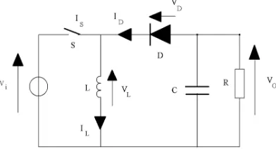
2.3 DC–DC Buck-Boost Converter
Buck boost converters are capable of increasing and decreasing the output voltage with respect to the input voltage [14]. It has been proposed in this paper in sequence with PV panel; since the PV panel voltage is varied with radiation.
The buck boost converter is designed with
at least two semiconductor switches such
as diode and a transistor
,
and at least two energy storage element, a capacitor and an inductor. Theswitch is typically of a MOSFET, IGBT or BJT
in
this paper MOSFET is proposed.
Figure 3shows the circuit of buck boost converter.
Figure 3. Schematic Of Buck-Boost Converter
The Buck boost converter is the combination of buck converter and boost converter. The output–input voltage conversion ratio is the conversion ratio of the two converters in cascade when the switches in both the converters have the same duty cycle. Buck–boost conversion ratio obtained through buck converter in the first stage results in a buck-boost-cascaded converter. Based on the requirement D can be varied widely which is necessary for the PV power system.
Buck-boost converter, thus does not have an on-operational zone that is no limitation for duty ratio. So changing the duty cycle enables operation from short-circuits current to open-circuit voltage of PV panel.
3. CONTROL STRUCTURE OF
STATCOM
Voltage oriented Vector control with grid voltage is the basic principle of the STATCOM [13]. It is the combination of two control structures such as inner current controllers and outer DC voltage and reactive power controllers. The control structure is adapted in four steps to guarantee safe operation and to achieve the given current injection targets under unbalanced grid voltage condition. 1. Positive and negative sequence detection based on dual second order generalized integrator's (DSOGI)
2. Current injection target calculation based on the power calculations under unbalanced grid voltage 3. Negative sequence current control using resonant controllers
4. DC voltage and reactive current control loop modifications.
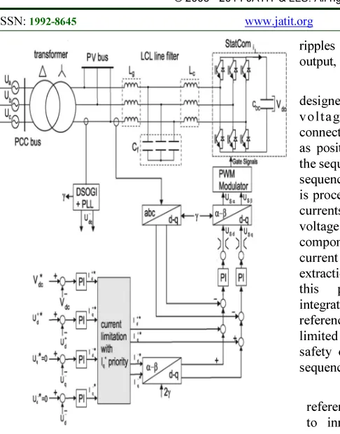
[image:3.595.91.287.621.727.2]Figure 4: The Proposed Control Structure Of The STATCOM To Control The Positive And The
Negative-Sequence Voltage Independently.
Proportional Integral (PI) controller is proposed in the inner current controllers a n d i n v o l t a g e c o n t r o l l e r in a rotating dq
reference frame with grid voltageorientation in
STATCOM. The PI controller equation is
. 5
The modeling and P I controller gain
design for three phase converter are described in
[15], [16].
The inner current loop is designed with a PI controller for negative sequence and positive sequence current in STATCOM. The overall control
structure is shownin Figure 3.
The number of levels of voltage source converter in the STATCOM is chosen based on
the power rating. Nominal power
applications are employed with two-level
voltage source converter, while multilevel
topologies will be used for high-power applications.
Since IGBTs are used in converter the output voltage is non sinusoidal, so LCL filter in sequence with the converter is proposed in this paper to remove
ripples and produce pure sine wave from inverter output,
The outer voltage control loops are designed to control the DC voltage and A C v olta g e. A C v ol ta ge is the voltage at the connection point of the STATCOM and is separated as positive and negative sequence voltage. Using the sequence separation, the positive and the negative
sequence of the voltage appear as dc values and it
is processed by PI controllers to produce reference
currents. It states the separation of the measured
voltage into positive- and negative- sequence
components decides the accuracy of reference current and voltage compensation. Many sequence extraction methods are discussed in [18], [19], in
this paper dual second-order generalized
integrators [17] is proposed. The current
references given by the four outer controllers are
limited to the maximum STATCOM current for
safety operation. The priority is on the positive-sequence reactive current.
The positive and negative sequence current
references are added to produce reference signals
to inner current loop. The negative sequence current references must be transformed into the positive rotating reference frame by a coordinate transformation with twice the grid voltage angle [20].
In this paper the balanced and unbalanced load faults in grid are compensated using positive-sequence voltage and the negative-positive-sequence
voltage compensation method.
4. SIMULATION RESULTS AND ANALYSIS
The system analyzed consists of a 1MW PV power system connected with the grid. The STATCOM is connected between PV system and
grid. The STATCOM is modeled as controlled
voltage sources. Both devices are connected to
the same low voltage bus and then connected to the medium voltage bus by a transformer. The
medium voltage level is connected to the high
voltage level by a second transformer. Both
transformers are rated for the sum of the PV
system and STATCOM power and have a series
impedance of5% and 10% per unit. The grid fault
is assumed at the high voltage level of the grid.
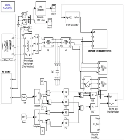
system with STATCOM is analyzed with various loads in the grid. , When sudden changes of load in the grid will create sag and swell in the grid voltage. In this paper, balanced and unbalanced loads are considered for analysis. The sudden rise in the load makes sag in voltage whereas a sudden drop in load causes swelling in voltage. The simulation model of the system is shown in figure 4.
Figure 5: The Simulation Model Of The System
[image:5.595.290.517.73.254.2]The system is initially with sag by balanced and unbalanced load. The figure 7 shows the sag caused by a sudden rise in load in three phases equally.
Figure 6: Sag In Voltage By Balanced Load Change
[image:5.595.89.288.228.453.2]Figure 6 shows that the uncompensated sag in three phase voltage. All phase voltages are suddenly reduced (sag) equally because of balanced load.
Figure 7: Sag In Voltage By Unbalanced Load Change
The figure 7 shows the sag caused by a sudden rise in load in three phases unequally.
Figure 8: Swell In Voltage By Balanced Load Change
[image:5.595.308.513.308.427.2]Figure 8 shows that the uncompensated swell in three phase voltage that is all phase voltages are suddenly raised (swell) equally because of balanced load.
Figure 9: Swell In Voltage By Unbalanced Load Change
[image:5.595.306.511.508.631.2] [image:5.595.89.292.521.642.2]Figure 10: Compensated Voltage By STATCOM
The figure 10 shows that the compensated voltage by the STATCOM for all above cases discussed. Figures 6-9 shows various instability in voltage due to change in load. From the figure 10 it is clear that the proposed STATCOM compensates oscillation in voltage and provides constant voltage.
5. CONCLUSION
Effective utilization of renewable energy is important than generation. Instability in voltage of grid connected PV system reduces efficiency of PV system and quality of voltage. To overcome this problem integration of grid connected PV system with the STATCOM is analyzed in this paper. The performance of STATCOM is analyzed with various parameters such as sag, swell, balanced and unbalanced load. From the simulation results it is
obvious that the STATCOM effectively
compensates the oscillations in voltage and maintains power quality. The application of STATCOM effectively increases the utilization of PV systems in grid. This control system may extend to other grid connected renewable power system.
R E F E R E N C E S
[1] BurriAnkaiah, Jalakanuru Nageswararao,
“Enhancement of Solar Photovoltaic Cell by Using Short-Circuit Current Mppt Method”, International Journal of Engineering Science Invention, Vol.2, No.2, 2013, pp.45-50. [2]. Eltawil, M.A. and Z. Zhao. Grid-connected
photovoltaic power systems: Technical and potential problems—A review. Renewable and Sustainable Energy Reviews, 14 (2010), No.1, 112-129.
[3]. E. Muljadi, D. Yildirim, T. Batan, and C.
Butterfield, “Understanding the
unbalanced-voltage problem in wind turbine
generation,” in Conf. Rec. 34th IEEE IAS
Annu. Meeting, 1999, vol. 2, pp. 1359–1365.
[4]. C. Hochgraf and R. Lasseter, “STATCOM
controls for operation with unbalanced
voltages,” IEEE Trans. Power Del., vol. 13,
no. 2, pp. 538–544, Apr. 1998.
[5]. C. Wessels, S. Grunau, and F. W. Fuchs,
“Current injection targets for a STATCOM
under unbalanced grid voltage condition and
the impact on the PCC voltage,” in Proc.
EPE Joint Wind Energy TD Chapters Sem., Apr. 2011.
[6]. P. Rodriguez, G. Medeiros, A. Luna, M.
Cavalcanti, and R. Teodorescu,“Safe current
injection strategies for a STATCOM under
asymmetrical grid faults,” in Proc. IEEE
ECCE, Sep. 2010, pp. 3929–3935.
[7]. B. Singh, S. Murthy, and S. Gupta, “STATCOM-based voltage regulator for self-excited induction generator feeding
nonlinear loads,” IEEE Trans. Ind.
Electron., vol. 53, no. 5, pp. 1437–1452, Oct. 2006.
[8]. A. Ortiz, T. Ostrem, and W. Sulkowski,
“Indirect negative sequence volt- age control
for STATCOM supporting wind farms
directly connected to the grid,” in proc.
IEEE 37th IECON, Nov. 2011, pp. 1903– 1908.
[9]. Roman Keding, David St¨uwe, Mathias Kamp, Christian Reichel, Andreas Wolf, Robert Woehl, Dietmar Borchert, Holger Reinecke, and Daniel Biro, “Co-Diffused Back-Contact Back-Junction Silicon Solar Cells without Gap Regions”, IEEE Journal of Photovoltaics,Vol.3,No.1,2013,,pp.236-1242.
[10]. Surya Kumari.J and Ch. SaiBabu,
“Mathematical Modeling and Simulation of Photovoltaic Cell using Matlab-Simulink
Environment”, International Journal of
Electrical and Computer
Engineering”,Vol.2,No.1,2012,pp.26-34. [11]. DorinPetreus, CristianFarcas, Ionut Ciocan,
“Modelling and simulation of photovoltaic cells ACTA”, Technicanapocensis Electronics an, Vol.48, No.1, 2008, pp.42-47.
[12]. Snyman D, Enslin J. An experimental evaluation of MPPT converter topologies for PV installations. Renewable Energy 1993; 3: 841–8.
[13]. M.Lokanadham, K.VijayaBhaskar,
“Incremental Conductance Based Maximum
Power Point Tracking (MPPT) for
[14]. Jain S, Agarwal V. A Single-stage grid connected inverter topology for solar PV Systems with maximum power point tracking, IEEE Transactions on Power Electronics, 2007; 22:1928–40.
[15]. H. Mahmood and J. Jiang, “Modeling and
control system design of a grid connected
VSC considering the effect of the interface
trans- former type,” IEEE Trans. Smart
Grid, vol. 3, no. 1, pp. 122–134, Mar.
2012.
[16]. J. Dannehl, C. Wessels, and F. W. Fuchs,
“Limitations of voltage oriented PI current
control of grid-connected PWM rectifiers
with LCL filters,” IEEE Trans. Ind. Electron.,
vol. 56, no. 2, pp. 380–388, Feb. 2009.
[17]. N. Hoffmann, L. Asiminoaei, and F. W.
Fuchs, “Online grid-adaptive control and
active-filter functionality of PWM-converters
to mitigate voltage unbalances and
voltage-harmonics a control concept based on
grid impedance measurement,” in Proc.
IEEE ECCE, Sep. 2011, pp. 3067–3074.
[18]. H. de Souza, F. Bradaschia, F. Neves, M.
Cavalcanti, G. Azevedo, and J. de Arruda,
“A method for extracting the
fundamental-frequency positive-sequence voltage vector
based on simple mathematical
trans-formations,” IEEE Trans. Ind. Electron., vol.
56, no. 5, pp. 1539–1547,May 2009.
[19]. N. Hoffmann, R. Lohde, M. Fischer, F. Fuchs, L. Asiminoaei, and P. Thogersen, “A review on fundamental grid-voltage detection
methodsunder highly distorted conditions in
distributed power-generation net- works,” in
Proc. IEEE ECCE, Sep. 2011, pp. 3045–3052.
[20]. M. Molinas, J. Suul, and T. Undeland,
“Extending the life of gear box in wind
generators by smoothing transient torque
with STATCOM,” IEEE Trans. Ind.