3-D SPACE FLIGHT FORMATION CONTROL FOR UAVS
BASED ON MAS
1, 2,*
YANSONG DENG, 1KAIYU QIN, 3GUANGMING XIE
1 Institute of Astronautics and Aeronautics, University of Electronic Science and Technology of China,
Chengdu, Sichuan, 610054, P. R. China
2 Institute of Electrical and Information Engineering, Southwest University for Nationalities of China,
Chengdu, Sichuan, 610041, P. R. China
3State Key Laboratory for Turbulence and Complex Systems and College of Engineering, Peking
University, Beijing 100871, P. R. China
* Corresponding author. E-mail: [email protected]
ABSTRACT
A Multi-Agent System(MAS) consensus based algorithm is proposed for Multi-UAVs to maintain a specified time-varying geometric configuration for formation flight in 3-D space. Use decoupling characteristics in altitude control of Multi-UAVs, formation problem in 3-D space, was decomposed altitude control and plane control. In this approach, the proposed control strategy requires only the local neighbor-to-neighbor information between vehicles. Speed, heading angle. Then height synchronization is realized and the 3-D space formation flight can be achieved, and formation transform was investigated. The simulation results show that, this method has good robustness and scalability, simple calculation and a small amount of communication, and make the formation in 3-D space become easy to implement.
Keywords: MAS, UAV, Consensus, Formation Flight, 3-D Space
1. INTRODUCTION
One kind of intelligent weapon system
development tendencies is the autonomous
formation and cooperative guidance technology of multiple unmanned aerial vehicles (UAVs) which fits for the demand of combat mission and fire distribution. Formation control technology as one of the main research in Multi-UAVs cooperative control, play important role to realize stable and safe flying for Multi-UAVs system. Recently, decentralized formation control relying on only
local information interaction and allowing
dynamical changing communication topologies has made rapid progress.
Numerous results have been obtained for distributed coordination of multiple agents[4-8]. For example, Lafferriere [4] studied a method for decentralized stabilization of vehicle formations using techniques from algebraic graph theory. Also, Olfati-Saber[5] considered a group of mobile second-order agents moving in the plane and introduced control laws which enable the group to achieve a common velocity while avoiding collisions. Ren[6] proposed several consensus algorithms for second-order multi-agent systems
and derived sufficient conditions for state consensus of the system. Moreover, Hong[7] investigated multiple second-order agent systems with jointly-connected interconnection topologies. In engineering practice, multi-agent systems are usually subjected to various disturbances such as time-delay and the variation of network topology. Lin [8] considered consensus problems for first-order multi-agent systems with external disturbances and model uncertainty on fixed and switching topologies.
ISSN: 1992-8645 www.jatit.org E-ISSN: 1817-3195
formation are formulated in Section 3. Section 4 offers detailed simulation results for formation flight in 3-D space of Multi-UAVs. Finally, conclusions are given out in Section 5, and some possible future directions of research are also discussed.
2. CONSENSUS PROBLEM
FORMULATION AND DEFINITIONS
2.1 Graph Theory
Let G( , ,V ε A) be a directed graph of order n,
where V={ ... }υ υ1 n is the set of nodes, ε⊆ ×V Vis
the set of edges, and A =[aij] is a weighted
adjacency matrix. The node indexes belong to a
finite index setI ={1, 2,..., }n . An edge of G is
denoted byeij =( ,v vi j). The adjacency matrix is
defined as aii =0and aij ≥0. aij >0 if and only if
ij
e ∈ε. The set of neighbors of node vi is denoted
by Ni ={vj∈V: ( ,v vi j)∈ε} . The in-degree and
out-degree of node vi are defined, respectively,
as
1 1
( ) , ( )
n n
in i ji o i ij
j j
d v a d v a
= =
=
∑
=∑
. Then, the graphLaplacian with the directed graph is defined as [ ]ij
L= l where lij =do ( )vi andlij = −a iij, ≠ j. An
important fact of L is that all the row sums of L
are zero and thus 1n is an eigenvector of L
associated with the eigenvalueλ =0. A directed
path is a sequence of ordered edges of the
form(vi1 , vi2 ), (vi2 , vi3 ), . . . ,where vij∈V.If a
directed graph has the properties that
( ,v vi j) belongs to ε for any ( ,v vi j)∈ε , the
directed graph is called undirected. If there is a directed path from every node to every other node, the graph is said to be strongly connected (connected for undirected graph).
2.2 Multi-agent Systems and the Concept of Consensus
The information states with agent dynamics are given by
1, 2,...,
i i
x =u i= n (1)
where n
i
x ∈R denotes the information state of
the ith agent and n
i
u ∈R is the control input. And
the consensus algorithm to reach an agreement with respect to the states of n integrator agents [1] can be
expressed as an nth-order linear system on a graph.
( ( ) ( )) , (0)
i
n
i j N ij i j i
u = −
∑
∈ a x t −x t x ∈R (2)whereaij is the
( )
i j, entry of the adjacency matrixof the associated communication graph at time t,
and Ni represents the set of agents whose
information is available from agent ∑iat time t.
The control ui drives xi to the average position of
its neighbors.
By applying algorithm Equ.(2), we can rewrite expression Equ.(1) into
( ) ( )
x t = −Lx t (3)
where [ ,...,1 ]
T n
x= x x denotes the aggregated state
vector of the multi-agent system, and L=[ ]lij is the
graph Laplacian of the network.
The set of agents V is said to be in consensus, if
0
i j
x −x = for each ( , ) : ; 1, 2,...,i j i j = n as
0
t≥t . The set of agents V is said to
asymptotically reach global consensus if for
anyxi(0) :i=1, 2,...,n, xi−xj →0 as t tends to
infinity for each( , ) : ; 1, 2,...,i j i j = n as t≥t0 .
The set of agents V is said to be global consensus
reachable if there exists an information update
strategy (protocol) for each x ii: =1, 2,...,n that
achieves global consensus asymptotically for V.
If take each UAV as a node of graph , the UAV's perception and communication relationship as edge, formation flight of Multi-UAVs system can also see as a graph, which shows Multi-UAVs system information topology, then it is easy to study the problem of Multi-UAVs system cooperative control by using the powerful tools : graph theory.
3. FORMATION FLIGHT OF MULTIPLE
UAVS BASED ON MAS CONSENSUS
3.1 Model of UAVs Formation Flight
We assume that each UAV is equipped with standard autopilots for heading hold and Mach hold.
Let ( , )x y , h , ϕ ,θ and v denote the inertial position, altitude, heading angle, tilt angle, and velocity for the UAV respectively. Then the resulting kinematic equations of motion are
(
)
(
)
(
)
cos , sin , ,
c c
v
c h h
x v y v
v v v
h h h h
ψ
ψ ψ
α ψ α ψ ψ
α α
= =
= − = −
= − + −
(4)
whereψc,θcand c
v are the commanded heading
v
α ,αθ, and αψ are positive constants. In addition,
we assume that each UAV has the constraints that
min max
min max
max
0 v v v
a v a a
ψ ω ω
< ≤ ≤ ≤ = ≤ = ≤
(5)
, , T
c c c
u= v θ ψ is the control input in my
simulation .
In this paper,we will use UAV model equ.(4) longitudinal decoupling characteristics. The UAV formation in 3-D space, is divided into attitude control and plane formation control. This paper presents a formation based on graph theory, formation graph and consensus algorithm.
3.2 Speed Synchronization
UAV has the positive speed limit and the minimum turning radius restrictions. Before the formation, the speed and heading angle of all the UAVs should keep synchronization. Thus, all UAVs remain aggregation state, and reduce the probability of collision between each other even if there is some interference. Now we will give synchronous speed control strategy and course synchronous control strategy respectively. In order to focus on the essential issues, we will assume that altitude is held constant.
First order dynamic model of the speed of
UAV: ,
(
)
c
i v i i i
v =α v −v . To solve consensus of the
speed problem, we use the following protocol:
(
)
,
1
i
c
i i i
v i
i ij i j
j N
v v u
u a v v
α
∈
= +
= − −
∑
(6)
3.3 Heading Angle Synchronization
The ith UAV can use two kinds of different path
to change from the current heading angle ψi to the
instruction heading angleψic.One way is along the
clockwise deflection, another way is along the counterclockwise deflection. Obviously the one of the two path is farther, and synchronization time will be greatly increased due to the UAV minimum turning radius limit. So in the course control, consensus algorithm based on the control strategy, should also ensure the deflection angle is less
than
π
. To solve consensus of the heading angleproblem, we use the following protocol:
(
)
1 1 i c
i i j i
j i
ψ ψ ψ ψ
∈
= + −
+N
∑
N(7)
Where
(
ψj−ψi)
is the heading angle errorsbetween adjacent UAVs, that should satisfy
c
i i
ψ
−ψ
<π
.If communication topology fixed, ifand only if communication network topology contains directed spanning tree, all UAVs flight speed and heading angle can asymptotically to converge [5], then all the UAVs flight speed and heading angle tend to be the same.
3.4 Height Synchronization
Height control problem is very important for Multi-UAVs formation in 3-D space. The common control method is Leader-Follower method, by measuring their own and pilot UAV relative height to adjust their height. One of the disadvantage of this method is the tracking error may be gradually enlarged. Taking it that the longitudinal movement and lateral movement of UAV in 3-D space is completely decoupled into account, distributed control strategy based on consensus algorithm can be taken to achieve height synchronization.
In order to make all the UAVs flight height tends to be the same as given value, we use the following protocol:
(
)
(
)
(
)
(
)
,
, ,
*
1
1 h i c
i i i i
h i h i
i i i i
n
ij i j i j
j
h h h u
u c h h kh
a h h h h
α
α α
γ
=
= + +
= − − −
− − −
∑
+
(8)
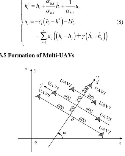
3.5 Formation of Multi-UAVs
y
UAV 1 UAV
2
UAV 3 UAV
4
200
200
200
400 400
ψ
v
UAV 5
x′
x
y′
o
o′
UAV 6
600 600
UAV 7
[image:3.612.315.525.399.661.2]200
Figure 1. Uav Formation Configuration
Assuming the position, speed and heading angle
ISSN: 1992-8645 www.jatit.org E-ISSN: 1817-3195
ground coordinate system, andx o y′ ′ ′ is the UAV
formation course coordinate system, and
v
andψ
are UAV formation speed and heading angle. In x o y′ ′ ′, and its relative position matrix can be
expressed as follows:
0 200 200 400 400 600 600 200 0 0 200 200 400 400 200 0 0 200 200 400 400 400 200 200 0 0 200 200 400 200 200 0 0 200 200 600 400 400 200 200 0 0 600 400 400 200 200 0 0
r ij x − − − − − − − − − − − − − − = − − − −
0 200 200 400 400 600 600 200 0 400 200 600 400 800 200 400 0 600 200 800 400 400 200 600 0 800 200 1000 400 600 200 800 0 1000 200
600 400 800 200 1000 0 1200 600 800 400 1000 200 1200 0
r ij y − − − − − − − − − = − − − − − − − − − − − −
Where,xijr = −xi′ x′j, yijr = yi′−y′j, qi′=
[
x yi′ ′, i]
Tisthe position coordinates of the th
i UAV in x o y′ ′ ′.
, T r r ij ij ij
r′ = x y is the ith UAV relative to expected
the jth UAV relative position coordinates.
The conversion relations between formation
course coordinate x o y′ ′ ′ and ground coordinate
system xoy is shown in Equ.(9). Formation
diagram and the position of UAV coordinates have been given, we can calculate formation constraint conditions as:
(
)
cos sin sin cos cos sin sin cosi j i j
i j
i j i j
i j
x x x x
q q
y y y y
q q ψ ψ ψ ψ ψ ψ ψ ψ ′− ′ − ′− ′ = ′ ′= − − − = − − (9)
So UAV formation flight control strategies can get as follow:
c c c
i i i
c c c
i i i
v v v
ψ ψ ψ
= + = +
(10)
where vic and
ψ
icare the synchronous control itemsof flight speed and heading angle based on consensus algorithm .The consensus algorithm
form is the same as equ.(6) and equ.(7). And vic ,
c i
ψ
is the formation control items based on
relative position feedback formation:
(
)
,
i
c r
i v i i j ij
j
v
k
x
x
x
∈
′
′
= −
∑
− −
N (11)
(
)
,
i
c r
i i i j ij
j
kψ y y y
ψ
∈
′ ′
= −
∑
− −
N (12)
where kv i, >0 , kψ,i>0 are positive feedback gain.
When they reach a balanced state, all UAVs fly according to the given geometric configuration formation, which should have
, 0
0
c c c
i i i
c c c
i i i
v v v v
ψ ψ ψ ψ
→ → →
→ → →
, (13)
That is, by adopting the control strategy for the UAV system, should ensure that the communication topology graph and the formation graph of distributed control strategy to meet the convergence condition.
In order to verify the proposed distributed formation flight control strategy is effective, in the 3-D simulation example. Assuming that all the UAVs models are the same, they have the same characteristic parameters
4. NUMERICAL SIMULATION
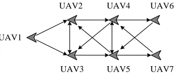
[image:4.612.336.514.508.584.2]Assume that there are 7 UAVs to form and maintain formation shown in Figure 1. The initial positions, speeds, heading angles, and height of UAVs in space are distributed arbitrarily. Initial state of UAVs is shown in the Table 1, the UAVs communication topology as shown in the Figure 2, and the weighted adjacency matrix takes as equ.(14). UAV2 UAV3 UAV4 UAV5 UAV1 UAV6 UAV7
Figure 3 Multi-UAVs Communication Topology
In the first stage, all UAVs used distributed control strategy Equ.(6) and Equ.(7), so that the
flight speed, and heading angle keep
synchronization. The UAV1 is group Leader, its speed instruction set to be 160 m/s, and heading
angle instruction set to be −π 4. After 10 seconds,
the speed instruction is changed to 200 m/s. From
the 20th seconds, the heading angle instruction is
height instruction is set to 13900. From the 40th seconds, system is switched to distributed control strategy Equ.(10) to form and keep formation shown in Figure 1.
The coefficients of distributed control strategy
equ.(11) and equ.(12) are set to be kv i, =1、
,i 0.001
kψ = , and we will obtain simulation results
[image:5.612.318.512.77.246.2]are as Figure 3 to Figure 7.
Table 1. Initial State of UAVs
Initial positon
Initial velocity
Initial heading
angle
Initial height UAV1 (0,0) 160 −π/ 4 13700 UAV2 (500,-100) 221.3 3 / 4π 14900 UAV3 (1000,-200) 245 −3 / 8π 15400 UAV4 (1500,1000) 178.3 −π/ 4 14000 UAV5 (1000,-500) 190.7 π/ 8 15000 UAV6 (-100,0) 180 −π/ 4 12500 UAV7 (-200,-1000) 200 π/ 8 14400
0 0 0 0 0 0 0 1 0 1 0 2 0 0 1 2 0 1 0 0 0 0 3 0 0 1 0 2 0 0 3 1 0 1 0 0 0 0 2 0 0 0 0 0 0 0 2 0 0 ij
A a
= =
(14)
0 20 40 60 80 100 120 140 160 150
200 250
t/s
v
(m
/s
)
0 20 40 60 80 100 120 140 160 -2
-1 0 1 2 3
t/s
ψ
(ra
d/
s)
UAV1 UAV2 UAV3 UAV4 UAV5 UAV6 UAV7
Figure 3 Change Flight Speed And Heading Angle
0 20 40 60 80 100 120 140 160 1.2
1.3 1.4 1.5 1.6x 10
4
t(s)
F
light
al
ti
tude(
m
) UAV1
UAV2 UAV3 UAV4 UAV5 UAV6 UAV7
0 20 40 60 80 100 120 140 160 -400
-200 0 200 400 600
t(s)
A
lt
it
ude c
hange r
at
e(
m
)
Figure 4. UAVs Flight Altitude and Altitude Change Rate
Easy to see that, when UAV1 flight speed or heading angle change, the rest of UAVs will follow the change, and tend to be consensus soon, and transient time is very short, as shown in Figure 3. So all UAVs flight speed and heading angle can keep synchronization under the distributed control strategy Equ.(6) and Equ.(7), so we can control the group leader to control the whole group.
As shown in Figure 4, all flight height quickly tends to be the same as the given value. When the operator setpoint changes, the consistent ( balance ) state will be broken, but soon the flight height tends to be the same as the new value.
-0.5 0 0.5
1 1.5 2 2.5 3 x 10⁴ -0.5
0 0.5 1 1.5 2 2.5 3
x 104 1.2 1.4 1.6
x 104
x y
h
[image:5.612.99.292.215.642.2]UAV1 UAV2 UAV3 UAV4 UAV5 UAV6 UAV7
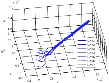
Figure 5. UAVs formation of 3-D space
[image:5.612.319.507.461.605.2]ISSN: 1992-8645 www.jatit.org E-ISSN: 1817-3195
In the actual formation flight, when emergency, because of the change of the environment or the task, may require the formation of UAVs system adjustment or conversion. In our method, only need to be given a desired formation diagram, and rationally design of topology structure.Then the formation of transform can be realized. As shown
in Figure 5, from the 40th seconds to the 100th
seconds, UAV formation configuration 1 is achieved, and the amplification of the formation is
shown in Figure 6 on the 100th seconds. From the
100th seconds to the 200th seconds, UAV formation
configuration 2 is achieved, and the amplification
of the formation is shown in Figure 7 on the 200th
seconds.
1.26 1.28 1.3 1.32 1.34 1.36 1.38 x 10⁴ 0.98
1 1.02 1.04 1.06 1.08 1.1 1.12
x 104
x(m)
y
(m
)
UAV1 UAV2 UAV3 UAV4 UAV5 UAV6 UAV7
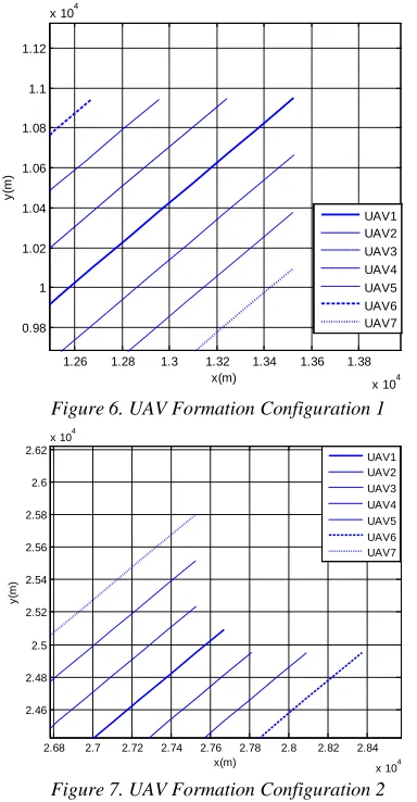
Figure 6. UAV Formation Configuration 1
2.68 2.7 2.72 2.74 2.76 2.78 2.8 2.82 2.84 x 10⁴ 2.46
2.48 2.5 2.52 2.54 2.56 2.58 2.6 2.62
x 104
x(m)
y
(m
)
[image:6.612.94.286.278.647.2]UAV1 UAV2 UAV3 UAV4 UAV5 UAV6 UAV7
Figure 7. UAV Formation Configuration 2
5. CONCLUSION
A consensus-based algorithm is proposed to maintain a specified time-varying geometric configuration for formation flight in 3-D space of Multi-UAVs. Speed, heading angle, and height
synchronization is realized and the 3-D space formation is achieved by the proposed consensus algorithm, which is shown in simulation. This research scheme laid the foundation for the application consensus algorithm for formation technology of Multi-UAVs, and some research can try in the problem for obstacle avoidance and crash avoidance in the formation control of Multi-UAVs.
A
CKNOWLEDGEMENTSThis work was supported by the Science Research Project of Southwest University for Nationalities (Grant No. 2012NFW002).
REFERENCES:
[1] Chandler P R, Pachter M, Rasmussen S. "UAV cooperative control", Proceedings of the American Control Conference. 2001, pp. 50-55. [2] Girard A R, Sousa J B, Hedrick J K. "An
overview of emerging results in networked multi-vehicle systems", Proceedings of the 40th IEEE Conference on Decision and Control, 2001,pp.1485-1490.
[3] Ryan A, Zennaro M, Howell A, et al. "An overview of emerging results in cooperative UAV control", Proceedings of the 43rd IEEE Conference on Decision and Control, 2004,pp.602-607.
[4] Lafferriere G, Williams A, Caughman J and
Veerman J 2005 System Control Letters, Vol.
54 , No.9, pp.899-910
[5] R. Olfati-Saber. "Flocking for Multi-Agent Dynamic Systems: Algorithms and Theory,"
IEEE Trans. on Automatic Control, vol. 51, No.3, Mar. 2006, pp. 401-420.
[6] Ren W. "On consensus algorithms for double-integrator dynamics", Proceedings of the 46th Conference on Decision and Control, New Orleans, USA, 2007, pp. 2295–2300
[7] Hong, Y., Gao, L., Cheng, D., Hu, J. "Lyapunov-based approach to multi-agent systems with switching jointly connected interconnection", IEEE Trans. Automat. Control, Vol.52, No.5, 2007, pp.943-948.
[8] P.Lin and Y.Jia, “Distributed robust
H∞ consensus control in directed networks of
agents with time-delay”, Systems and Control
Letters, Vol. 57 , No.8, 2008, pp. 643-653. [9] Ren W, Beard R W, Atkins E M. “Information
interaction”, IEEE Control System Magazine,
Vol. 27, No.2, 2007, pp. 71-82.
[10] Innocenti M, Polloni L, Turra D. “A fuzzy approach to the guidance of unmanned air
vehicles tracking moving targets”, IEEE
Transactions on Control System Technology,
Vol. 16, No.6, 2008, pp. 1125-1137.
[11] Olfati-Saber R, Murray R M. “Consensus problems in networks of agents with switching
topology and time-delays”,IEEE Transactions
on Automatic Control, Vol. 49, No.9, 2004, pp. 1520-1533.
[12] Ren W, Beard R W. “Consensus seeking in multiagent systems under dynamically changing
interaction topologies”, IEEE Transactions on
Automatic Control, Vol.50, No.5, 2005,pp. 655-661.
[13] Xie G, Wang L. “Consensus control for a class
of networks of dynamic agents”. International
Journal of Robust and Nonlinear Control,
Vol.17, No.10-11, 2007, pp. 941-959.
[14] Ren W, Atkins E. “Distributed multi-vehicle coordinated control via local information
exchange”. International Journal of Robust and
Nonlinear Control, 2007, Vol.17, No.10-11, pp.1002-1033.