LoFi: A TURBOchannel Audio Module
Thomas M. Levergood
Digital Equipment Corporation Cambridge Research Lab
Paris; and the Cambridge Research Laboratory, in Cambridge, Massachusetts.
The Cambridge laboratory became operational in 1988 and is located at One Kendall Square,
near MIT. CRL engages in computing research to extend the state of the computing art in areas
likely to be important to Digital and its customers in future years. CRL’s main focus is
applications technology; that is, the creation of knowledge and tools useful for the preparation of
important classes of applications.
CRL Technical Reports can be ordered by electronic mail. To receive instructions, send a
mes-sage to one of the following addresses, with the word
helpin the Subject line:
On Digital’s EASYnet:
CRL::TECHREPORTS
On the Internet:
[email protected]
This work may not be copied or reproduced for any commercial purpose. Permission to copy without payment is granted for non-profit educational and research purposes provided all such copies include a notice that such copy-ing is by permission of the Cambridge Research Lab of Digital Equipment Corporation, an acknowledgment of the authors to the work, and all applicable portions of the copyright notice.
The Digital logo is a trademark of Digital Equipment Corporation.
Cambridge Research Laboratory
One Kendall Square
Cambridge, Massachusetts 02139
LoFi: A TURBOchannel Audio Module
Thomas M. Levergood
Digital Equipment Corporation Cambridge Research Lab
CRL 93/9 June 17, 1993
Abstract
LoFi is a single-slot TURBOchannel module designed as a research prototype to interface to a variety of audio sources and sinks. LoFi contains two 8 KHz CODECs, a digital signal processor with 32K words of static memory, a 44.1 KHz stereo digital-to-analog converter, and analog and digital telephone line interfaces. This report is the technical reference for the LoFi module and includes descriptions of the hardware design and programming interface. A source code kit containing LoFi support software is available by anonymous FTP.
Keywords: audio hardware, digital signal processor, multimedia, telephone inter-face
c Digital Equipment Corporation 1993. All rights reserved.
Touch-Tone is a trademark of AT&T.
UNIX is a trademark of Unix Systems Laboratories. IOM-2 is a trademark of Siemens AG.
CONTENTS i
Contents
1 Introduction 1
2 Hardware Overview 1
2.1 DSP Section : : : : : : : : : : : : : : : : : : : : : : : : : : : : 2
2.2 CODEC Section : : : : : : : : : : : : : : : : : : : : : : : : : : 3
2.3 Telephone Line Interface Section : : : : : : : : : : : : : : : : : 4
2.4 I/O Section : : : : : : : : : : : : : : : : : : : : : : : : : : : : : 8
3 Programming Interface 11
3.1 TURBOchannel Host Perspective : : : : : : : : : : : : : : : : : 11
3.1.1 Diagnostic ROM : : : : : : : : : : : : : : : : : : : : : : 11
3.1.2 DSP Host Port : : : : : : : : : : : : : : : : : : : : : : : 12
3.1.3 Shared RAM : : : : : : : : : : : : : : : : : : : : : : : : 13
3.1.4 I/O Control Register : : : : : : : : : : : : : : : : : : : : 13
3.1.5 I/O Status Register : : : : : : : : : : : : : : : : : : : : : 15
3.1.6 Remote CODEC : : : : : : : : : : : : : : : : : : : : : : 17
3.1.7 Local CODEC : : : : : : : : : : : : : : : : : : : : : : : 17
3.1.8 Interrupts : : : : : : : : : : : : : : : : : : : : : : : : : 18
3.1.9 I/O Transaction Costs : : : : : : : : : : : : : : : : : : : 20
3.2 DSP56001 Perspective : : : : : : : : : : : : : : : : : : : : : : : 21
3.2.1 Memory Map : : : : : : : : : : : : : : : : : : : : : : : 21
3.2.2 Interrupts : : : : : : : : : : : : : : : : : : : : : : : : : 23
3.2.3 Serial I/O : : : : : : : : : : : : : : : : : : : : : : : : : 23
4 Device Driver 27
5 Diagnostic and Test Software 31
6 Summary 33
1
1
Introduction
In 1990, we began to deploy DECstation 5000 Model 200 workstations at Digital’s Cambridge Research Lab (CRL). Since this workstation did not have audio I/O, I designed LoFi, a TURBOchannel peripheral, to provide the base hardware capa-bilities for performing audio experiments and research using the computing power of these workstations.
Since our interests in audio applications were varied, we needed a flexible device that would support real-time audio recording and playback, connect to the analog and digital telephone networks, as well as connect to external devices supporting high fidelity analog-to-digital and digital-to-analog conversion. The LoFi device was designed to meet these needs.
During the design phase, a Digital product group became interested in making LoFi a product. The product group designed the external distribution box for LoFi and made a few other changes before introducing “DECaudio” to the marketplace in 1991.
We have been using LoFi in DECstation workstations at CRL since 1990 and are now using LoFi in our Alpha AXP workstations. The original design has met our desktop audio I/O needs ranging from 8 KHz telephone quality speech to higher fidelity sampling for continuous speech recognition and music synthesis.
This document includes an overview of the LoFi hardware design and its capabil-ities, the hardware programming interface, and information specific to the digital signal processor and kernel device driver. For software above the level of the device driver and diagnostics, we use AudioFile, a system providing network-transparent, device-independent audio services[8, 9].
2
Hardware Overview
The DECstation 5000 Model 200 was the first system to use the TURBOchannel I/O bus [3, 4, 5, 6]. This bus has several nice properties including a simple interface specification as well as reasonable data transfer rates. The first Alpha AXP workstations also use the TURBOchannel for their I/O bus.
However, I chose to design LoFi as a TURBOchannel module for two reasons: to allow for low-latency operations where required and to reduce the hardware and software design time. This decision constrained the physical design because of the size of the module and limited the features that could be included.
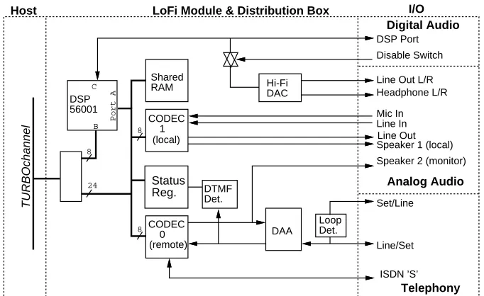
Figure 1 is a block diagram of LoFi. The major blocks include the digital signal processor, shared memory, the two 8 KHz CODECs, and the telephone line inter-face. The major blocks are interconnected via a 24-bit data bus. The I/O section is grouped into three categories emphasizing the digital audio, analog audio, and telephony capabilities of the hardware.
DSP 56001 CODEC 1 CODEC 0 (remote) DAA Hi-Fi DAC DSP Port Loop Det. Set/Line Line/Set ISDN ’S’
Speaker 2 (monitor) Shared
RAM
TURBOchannel
Speaker 1 (local)Line Out Line In Mic In Line Out L/R Headphone L/R Disable Switch I/O Digital Audio Analog Audio Telephony (local) DTMF Det. Host Status Reg.
LoFi Module & Distribution Box
Port A B C 24 8 8 8
Figure 1: LoFi block diagram
2.1 DSP Section
2.2 CODEC Section 3
in host software [15].
The digital signal processor on LoFi is the Motorola DSP56001[11]. The DSP56001 is clocked by a 27 MHz oscillator and will execute a 24x24 bit multiply/accumulate instruction in 74 nanoseconds. The DSP56001 has 512 words of on-chip data mem-ory and 512 words of on-chip program memmem-ory. Memmem-ory is expanded off-chip with a 32Kx24 bit static RAM array. The DSP56001 operates with zero wait states in the external memory. This memory is shared by the DSP56001 and the host processor.
The DSP56001’s “Port C” contains two serial interfaces that can be used to connect to an external source and sink of digital audio. The serial port signals are brought out to a 15 pin connector that is compatible with the NeXT DSP serial port [16]. This DSP port allows LoFi to connect to a variety of third party devices.
LoFi includes an integral stereo DAC, connected to Port C, operating at a 44.1 KHz sampling frequency. The DAC is a Phillips SAA7323 device [14]. Stereo audio can be played through the DAC under DSP software control (see Section 3.2.3 for code examples). The DAC was placed within the distribution box in order to better control for potential noise sources.
I selected the DSP56001 for several reasons. At that time, this DSP chip had attractive price/performance and system design attributes. Further, the “DSP port” appeared to be edging towards an industry standard interface since Ariel Corporation1 and other companies were introducing products that connected di-rectly to this interface. Finally, the greater dynamic range supported by the 24-bit word (and 56-bit accumulator) in the DSP56001 was attractive when compared to 16-bit DSP chips.
2.2 CODEC Section
For telephone-quality audio input and output, LoFi uses two AMD Am79C30A Digital Subscriber Controllers which are commonly referred to by “CODEC” 2 because of their ADC/DAC function. The two CODECs perform distinct functions on LoFi. The “remote” CODEC is used to interface to the received telephone audio, the transmitted telephone audio, and a monitor speaker output. The “local” CODEC is used to interface to a microphone or line level input and a speaker or line level output.
1
Highland Park, NJ, USA. 2
The Am79C30A is intended to function as the interface between a telephone handset and the ISDN S connection within an ISDN telephone. For more details on this part also see the manufacturer’s data sheet [1].
The Am79C30A contains several sections including those supporting an analog handset interface, a microprocessor interface, and an ISDN S interface.
The “main audio processor” (MAP) sections within the two Am79C30A devices are used to support the analog interfaces to the telephone line interface and the local audio I/O on LoFi. Each MAP can select between two analog inputs and two analog outputs. The MAP includes programmable gain control and filtering capabilities. The input stage has a preamplifier with programmable gain between 0 and 24 dB. One of the MAP’s outputs is designed to drive a 50 Ohm loudspeaker. The other output can be used as a line level driver. The MAP’s CODEC operates at a fixed 8 KHz sample rate with 8-bit-law or A-law (logarithmic PCM) encoding
resulting in a 64 Kbps per channel data rate. Refer to CCITT G.711 for a complete description of the-law and A-law encodings.
The digital signal processor and the TURBOchannel host communicate with the Am79C30A via the byte-wide “microprocessor interface” (MPI).
The Am79C30A has an integrated ISDN S “line interface unit” (LIU). The LoFi hardware contains the necessary external components to connect to an ISDN S interface.
There is a multiplexer (MUX) internal to the Am79C30A. The MUX is pro-grammable and can be configured to route data between any two of the MAP, MPI, and LIU sections. On LoFi, the MAP and MPI sections are generally connected so the MAP serves as the source and sink of digital audio data from the DSP or host processor.
The local and remote CODECs are also connected via the Am79C30A IOM-2 interface. The remote CODEC is the IOM-2 bus master and the local CODEC is the slave. With appropriate software configuration, the 8 KHz frame interrupt from each CODEC can be synchronized.
2.3 Telephone Line Interface Section
follow-2.3 Telephone Line Interface Section 5
ing features:
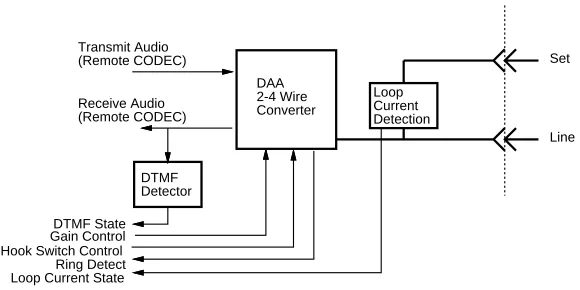
2 to 4 wire converter hybrid
typical trans-hybrid loss of 18 db
ring detect circuitry (sensitivity 38 Vrms)
hook-switch control relay
protection circuitry
The product version of LoFi, DECaudio, includes a minor modification to support the DS2249PH version of the DAA. The most interesting feature of the DS2249PH is that it includes an automatic gain control circuit limiting the average power level to the telephone line. Some regulatory agencies require compliance to transmitted power level limits in order to minimize inter-channel interference in frequency di-vision multiplexed systems within the PSTN.3The gain limiting circuitry monitors the signal output to the telephone line and attenuates the gain in its path to prevent the output power from exceeding -4 dBm. The DS2249PH monotonically adjusts the attenuation and only restores the circuit to unity gain when the gain control circuit is disabled. The gain in this stage ranges from 0 to -10.0 dB.
DAA 2-4 Wire Converter
Loop Current Detection
Set
Line
DTMF Detector Transmit Audio (Remote CODEC)
Receive Audio (Remote CODEC)
[image:11.612.143.433.426.571.2]Hook Switch Control Ring Detect Loop Current State DTMF State Gain Control
Figure 2: Analog telephone line interface
There are two modular phone jacks provided for connection to a phone line and to a phone set (as shown in Figure 4). By convention, the outermost jack is the
3The power in the transmitted signal is governed by the Federal Communications Commission in
“line” jack and the connector between the line jack and the DB60R connector is the “set” jack. The DAA is directly connected to the line jack, and the two jacks are connected through a loop-current sensing relay. A desktop phone can be connected to the same phone line as LoFi and will continue to work when the workstation is powered off or reset.
The path between the two modular connectors includes a loop-current sensing relay circuit. The relay closes in response to line current in excess of 20 mA. This circuit is used to track the state of current flowing in the local loop in order to monitor hook-switch status and pulse dialing.
Connecting the phone set to the set connector causes the loop-current detector to assert an interrupt whenever the extension phone goes off-hook. Connecting the wall jack to the set connector causes the loop-current detection circuit to assert an interrupt whenever the DAA goes off-hook or the extension phone goes off-hook.
Dual tone multi-frequency (DTMF) detection is necessary for accepting remote input when connecting to the telephone network. The dual tone multi-frequency signaling used in the telephone network is also known as Touch-Tone signaling. Although DTMF detection is a trivial signal processing application, it is a function that must be present at all times. To reduce the computational overhead and software complexity on the DSP or host processor, an inexpensive integrated DTMF detector is used instead. The detector will recognize DTMF signals from the telephone line when the DAA is off-hook and a call is in progress as well as from the attached phone set.
The Mitel 8870CS DTMF decoder [10] is used on LoFi. It recognizes the complete 16 key Touch-Tone keypad consisting of the keys 0-9,, # and the military keys
A, B, C, and D. This decoder uses an external resistor/capacitor network to set its “guard time”. The LoFi design uses 560K Ohm and 0.1F components to set a 45
millisecond digit detection time and 45 millisecond interdigit interval.
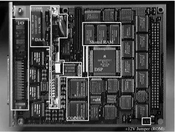
Module Image
Figure 3 is an image of the top-view of the LoFi module. The module is a single-slot TURBOchannel form factor (5.675 x 4.6 inches). The TURBOchannel I/O bus connector is located on the right-hand side of this image. The bulkhead and I/O connectors are located on the left.
2.3 Telephone Line Interface Section 7
1 DSP
Shared RAM I/O
CODECs DAA
[image:13.612.112.468.147.416.2]+12V Jumper (ROM)
Figure 3: LoFi module, top view
detector, and the loop-current sense relay.
2.4 I/O Section
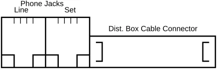
LoFi has three connectors along its bulkhead opening (see Figure 4). From left to right, these connectors are the RJ-11 telephone line service connector (line), the RJ-11 extension phone connector (set), and the 60 pin distribution box cable connector.
Dist. Box Cable Connector Phone Jacks
[image:14.612.217.433.229.299.2]Line Set
Figure 4: Module bulkhead connectors
Because of the limited bulkhead connector space on TURBOchannel options, a cable is used to connect the module to an external distribution box. The distribution box is used to break out to the connectors listed in Table 1. Appendix A contains information on the pin-outs for the DSP, DC power, and handset I/O connectors.
The microphone jack provides a 2.5 VDC bias for an attached low voltage electret microphone. An internal speaker is included in the distribution box. Inserting a 1/8" plug into the speaker jack disconnects the internal speaker. The modular handset connector is compatible with most telephone handsets/headsets containing a low voltage electret microphone. We generally use a lightweight headset model.4
The modular power supply used with the distribution box is a 40 W supply with a detachable line cord. AC input between 90-260 VAC and 47-440 Hz is allowed. The supply provides 3 DC output voltages; +5 VDC at 3A, +12VDC at 2A, and -12 VDC at 0.3A. This supply is compatible with the power requirements of the distribution box and with the power supply connector described in Table 10. The power supply is needed to supply power to the stereo DAC, the speaker amplifier, and the DSP port.
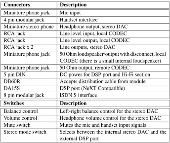
Figure 5 is an image showing the LoFi module and the front panel of the distribution box. The connectors and switches that are needed frequently are located on the front panel. Figure 6 shows the rear panel of the distribution box. The jacks for “permanent” connections are located here.
4
2.4 I/O Section 9
Connectors Description
Miniature phone jack Mic input
4 pin modular jack Handset interface
Miniature stereo phone Headphone output, stereo DAC
RCA jack Line level input, local CODEC
RCA jack Line level output, local CODEC
RCA jack x 2 Line outputs, stereo DAC
Miniature phone jack 50 Ohm loudspeaker/output with disconnect, local CODEC (there is a small internal loudspeaker) Miniature phone jack 50 Ohm output, remote CODEC
5 pin DIN DC power for DSP port and Hi-Fi section
DB60R Accepts distribution cable from module
DA15S DSP port (NeXT Compatible)
8 pin modular jack ISDN S interface
Switches Description
Balance control Left-right balance control for the stereo DAC Volume control Headphone volume control for the stereo DAC Mute switch Mutes the mic and handset input signals
[image:15.612.115.459.243.533.2]Stereo mode switch Selects between the internal stereo DAC and the external DSP port
Figure 5: LoFi module and distribution box
[image:16.612.181.469.397.615.2]11
3
Programming Interface
This section provides the information necessary to write software for LoFi. This information is organized with a view towards writing TURBOchannel host and DSP56001 software and is presented separately.
3.1 TURBOchannel Host Perspective
Each TURBOchannel option slot occupies physical address space with a system dependent size between 4 and 512 MB. A module’s base address is determined by its TURBOchannel slot and is specific to the host system. LoFi uses 1 MByte of an option slot’s physical address space for its memory map. Lazy decoding on the module replicates this memory map at modulo 1 MB boundaries to the top of the option slot’s address space.
[image:17.612.126.452.617.663.2]LoFi presents a simple programmed I/O interface to a TURBOchannel host pro-gram. The ULTRIX and OSF/1 device drivers (described in Section 4) permit a user process to map a LoFi’s TURBOchannel I/O address space into its virtual address space. User code only needs to use the module base address returned by the device driver and the offsets documented below.
Table 2 describes the seven memory regions contained within LoFi’s 1 MB address space. All offsets contained in Table 2 are relative to the module base address. The size field in this table represents the range of each region as decoded by the hardware. The actual size of the mapped hardware within each region may be smaller. Visible to TURBOchannel host software are the diagnostic ROM, DSP host port, shared static memory, I/O control and status register, and the CODECs. LoFi provides 32 bits of data on read cycles and accepts 32 bits of data on write cycles. LoFi does not support byte write operations. Depending on the memory region addressed in a read cycle, some fields within the 32-bit word may contain unpredictable data.
3.1.1 Diagnostic ROM
0xbb+00000: unpredictable unpredictable unpredictable ROM data
31 . . . . 24 23 . . . .16 15 . . . . 8 7 . . . . 0
Offset Size Region (bytes)
0x000000 256K Diagnostic ROM (2 copies) 0x040000 256K DSP host port
0x080000 256K Shared RAM (2 copies) 0x0FA000 4 I/O control register 0x0FA000 4 I/O status register
[image:18.612.162.494.135.264.2]0x0FE000 32 Remote CODEC 0 <register index from 4:2> 0x0FE020 32 Local CODEC 1 <register index from 4:2>
Table 2: LoFi TURBOchannel option address map
In accordance with the TURBOchannel specification, LoFi contains a non-volatile memory. This memory is a 28F256 (32Kx8) flash EEPROM [7].
The ROM appears at 0x00000 offset from the module base address (0xbb). ROM data appears on byte 0 of the TURBOchannel. Read data on the other bytes are unpredictable. The ROM is indexed by TURBOchannel address bits <16:2>.
The ROM contains an eight character module identifier field [4]. The LoFi pro-totype ROM contains the eight character string “LoFi ” while the product module contains “AV01B-AA”.
When re-programming the 28F256, the user must insert a jumper to provide the +12V (Vpp) programming voltage to the device. Moreover, the 6 microsecond write recovery time required by the device is not guaranteed by the LoFi module itself. Software must ensure that the device is not accessed within 6 microseconds of a previous write. Furthermore, the LoFi hardware does not guarantee the minimum/maximum write cycle interval specification.
3.1.2 DSP Host Port
0xbb+40000: unpredictable unpredictable unpredictable Port B data
31 . . . . 24 23 . . . .16 15 . . . . 8 7 . . . . 0
Read/Write
3.1 TURBOchannel Host Perspective 13
bytes are unpredictable. The host port is indexed by TURBOchannel address bits <12:9>. The low three address bits <11:9> specify the host port address. The high address bit in that field indicates a read or write cycle. 5 Read transactions should set bit <12> to 1. Write transactions should set bit <12> to 0.
For more details on the DSP host port, refer to the DSP56001 User’s Manual [11].
3.1.3 Shared RAM
0xbb+80000: RAM byte 2 RAM byte 1 RAM byte 0 unpredictable
31 . . . 24 23 . . . .16 15 . . . 8 7 . . . 0
Read/Write
The shared memory size is 32Kx24 bits, with the memory appearing on the upper three bytes on the TURBOchannel data-bus. Read data on the low byte is unpre-dictable. The shared RAM is indexed by TURBOchannel address bits <16:2>.
Since the DSP56001 has a 24-bit data word, I had to decide how to align the DSP’s data path (and the shared RAM) with the TURBOchannel’s data bus. If the DSP’s data bus were aligned with the lower three bytes then the upper byte would be unpredictable on host read cycles. I could have added hardware to sign extend bit <23> through bits <24> to <31> but this did not seem reasonable given the limited space for extra components. Sign extension could be performed in host software, but I chose instead to align the DSP’s data bus with the upper three bytes of the TURBOchannel. Host software can clear the low order byte on read data, leaving a valid 32-bit signed integer without requiring shift operations on the data.
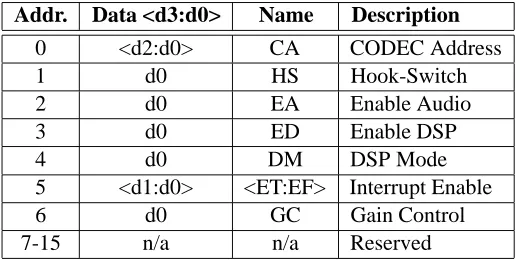
3.1.4 I/O Control Register
0xbb+FA000:
31 28 27 24 23 . . . .16 15 . . . . 8 7 . . . . 0
Addr. Data SBZ SBZ SBZ
Write
LoFi’s control register can be used to independently address sixteen control register fields. Each control register field is written by specifying a unique address field and
5An address bit was used to identify the cycle type to overcome a timing mismatch between the
a data field. The supported contents of the address and data fields are documented in Table 3.
Addr. Data <d3:d0> Name Description
0 <d2:d0> CA CODEC Address
1 d0 HS Hook-Switch
2 d0 EA Enable Audio
3 d0 ED Enable DSP
4 d0 DM DSP Mode
5 <d1:d0> <ET:EF> Interrupt Enable
6 d0 GC Gain Control
7-15 n/a n/a Reserved
Table 3: I/O control register field descriptions
The CODEC Address (CA) field in the control register should not be written by the host. Use of this field is reserved for DSP firmware and is described in Section 3.2.1.
The Hook-Switch field (HS) is used to control the state of the telephone line interface’s hook-switch relay. When HS is set, the telephone line interface goes off-hook. If HS is cleared, the interface goes on-hook. The reset condition is on-hook.
The Enable Audio field (EA) controls the reset input on the Am79C30A devices. When EA is set, the Am79C30A CODECs are enabled. The CODECs are disabled by the TURBOchannel reset.
The Enable DSP field (ED) controls the reset input on the DSP56001 device. When ED is set, the DSP is enabled. The hardware will not allow the DSP to write this field. The reset condition is disabled.
The DSP Mode field (DM) is used to control the DSP mode pins [11]. The host should set this field to the desired mode prior to enabling the DSP. When clear, the DSP mode is set for normal expanded mode (MODB=1, MODA=0). When set, the mode is set for single chip mode (MODB=0, MODA=1). The reset condition is clear. We generally bootstrap the DSP using normal expanded mode.
[image:20.612.196.454.173.303.2]3.1 TURBOchannel Host Perspective 15
Section 3.1.8 provides more detail on LoFi’s interrupt sources.
The GC field controls the “Gain Control” circuit of the DS2249PH on the product version of LoFi. When this field is set, the gain control circuit is enabled. Clearing this field disables the gain control circuit. The reset condition is clear. The hardware will not allow the DSP to write this field.
3.1.5 I/O Status Register
0xbb+FA000: unpredictable
31 . . . . . . . . 0
Status Register Fields
14 13
Read
The status register (read) contents are described in Tables 4 and 5.
Bit Field Name Description
31 ˜ codec1stat CODEC 1 interrupt state. This bit is 0 when the interrupt is asserted.
30 ˜ codec0stat CODEC 0 interrupt state. This bit is 0 when the interrupt is asserted.
29 EF Frame interrupt enable state for the TURBOchannel. This bit is 1 when the 8 KHz sample interrupt is en-abled. This bit is a read-only copy of the EF field in the I/O control register.
28 ET TLI interrupt enable state for the TURBOchannel. This bit is 1 when the telephone interrupts (ring, loop-current, DTMF detect) are enabled. This bit is a read-only copy of the ET field in the I/O control register. 27 ringstat Ring interrupt state. This bit is 1 during the ringing
“on” period. This bit is 0 during the ringing “off” period.
26 lcdstat Loop-current detect state. This bit is 1 when loop-current has been detected. If an extension phone is connected to the set jack, lcdstat indicates that the extension phone is off-hook.
[image:21.612.106.472.343.624.2]Bit Field Name Description
25 dtmfstat DTMF detection interrupt state. This bit is 1 when a DTMF key has been detected.
24:21 dtmf<3:0> DTMF key. See Table 6 for the coding of this field. 20 dtmf valid This bit is 1 when the dtmfstat and dtmf<3:0> are
valid. dtmfstat and dtmf<3:0> should be ignored when this bit is 0.
19 ˜ hoststat DSP host interrupt state. This bit is 0 when the DSP has interrupted the host.
18 Reserved Unpredictable on read.
17 DM DSP boot mode control state. Indicates the mode of the DSP56001 when it leaves the reset state. This bit is a read-only copy of the DM field in the I/O control register.
16 EA Enable audio state. This bit is 1 when the CODECs are enabled. This bit is a read-only copy of the EA field in the I/O control register.
15 HS Hook-switch control. This bit is 1 when the telephone hook-switch has been commanded off-hook. This bit is a read-only copy of the HS field in the I/O control register.
14 ED Enable DSP state. This bit is 1 when the DSP is enabled. This bit is a read-only copy of the ED field in the I/O control register.
13:0 Reserved. Unpredictable on read.
[image:22.612.148.502.136.482.2]3.1 TURBOchannel Host Perspective 17
1209 Hz 1336 Hz 1477 Hz 1633 Hz
697 Hz 1 0x1 2 0x2 3 0x3 A 0xD
770 Hz 4 0x4 5 0x5 6 0x6 B 0xE
852 Hz 7 0x7 8 0x8 9 0x9 C 0xF
[image:23.612.158.422.136.241.2]941 Hz * 0xB 0 0xA # 0xC D 0x0
Table 6: DTMF key decoding: Key dtmf<3:0> code.
3.1.6 Remote CODEC
0xbb+FE000: unpredictable unpredictable Data unpredictable
31 . . . . 24 23 . . . .16 15 . . . . 8 7 . . . . 0
Read/Write
The remote CODEC handles the telephone line audio and the ISDN S interface. The analog A input is connected to the receive telephone line audio. The Ear output is connected to the transmit telephone line audio. The loudspeaker output drives the second loudspeaker output on the distribution box for use as an alternate local output.
CODEC data appears on byte 1 of the TURBOchannel. Read data on the other bytes are unpredictable. The CODEC’s registers are indexed by TURBOchannel address bits <4:2>.
Refer to the Am79C30A Revision E data sheet for further information on program-ming the CODECs [1].
3.1.7 Local CODEC
0xbb+FE020: unpredictable unpredictable Data unpredictable
31 . . . . 24 23 . . . .16 15 . . . . 8 7 . . . . 0
Read/Write
connector. The loudspeaker output drives the distribution box speaker and the speaker 1 connector.
CODEC data appears on byte 1 of the TURBOchannel. Read data on the other bytes are unpredictable.The CODEC’s registers are indexed by TURBOchannel address bits <4:2>.
3.1.8 Interrupts
The TURBOchannel I/O bus supports one hardware interrupt per option module. The logical OR of several independent interrupt sources can cause LoFi’s TUR-BOchannel interrupt to assert. The interrupt signal is cleared by reading the I/O status register.
Host Request Interrupt
The “Host Request” interrupt allows the DSP to alert the TURBOchannel host that the DSP needs servicing. This interrupt may be used in support of inter-processor communication in the shared memory. The Host Request interrupt can be enabled through the host port of the DSP [11].
Real-Time Frame Interrupts
The second source of interrupts are the “real-time” interrupts. Each CODEC has an interrupt output that can be asserted once every frame (125 microseconds) when the output is enabled through the microprocessor interface. If the ET field is set in the I/O control register, then the assertion of either CODEC interrupt output will cause a TURBOchannel interrupt.
The CODEC interrupts can be synchronized on a frame level so that there will be no more than 10 microseconds between assertion of the remote and local CODEC interrupts (the remote CODEC interrupt follows the local CODEC interrupt). This is achieved using this pseudocode initialization sequence of the remote and local CODECs:
/* Configure primary vs. slave IOM-2 mode. * Remote CODEC0 is the master.
* Local CODEC1 is the slave. */
codec_write_1(lofi, CODEC_SLAVE, PP_PPCR1, PP_PPCR1_BITS_IOMS); /*... */
3.1 TURBOchannel Host Perspective 19
The first statement writes the PP PPCR1 register in the slave CODEC on the specified LoFi module. The subsequent statement initializes the same register in the master CODEC on the same LoFi module. The second statement sets the IOM master bit and IOM active bit for the master CODEC in the PP PPCR1 register. In general, only the remote CODEC’s interrupt output is enabled after host software initializes the CODECs as described above. Further, the EF field is never set during normal operation — the DSP firmware receives the CODEC frame interrupt and moves audio data between shared memory and the CODECs.
Telephone Interface Interrupts
The third set of interrupts is related to the telephone interface. The ring detection interrupt, the DTMF detection interrupt, and the loop current detection interrupt are enabled when the ET field is set in the I/O control register.
Incoming rings are detected by the telephone line interface hardware. An interrupt is generated for each transition of the ringing state (rings are nominally 2 seconds on and 4 seconds off).
DTMF interrupts are generated for each transition of the DTMF detection status indicating the beginning and end of a Touch-Tone key. DTMF interrupts with dtmf stat set should be ignored if the dtmf valid bit is not set in the I/O status register.6
Loop-current interrupts are generated for each transition of the loop-current detec-tion state. If an extension telephone is connected to the set connector, software can uniquely determine the state of the extension phone’s hook-switch. The loop-current status bit in the I/O status register will be asserted if the extension phone is off-hook. Pulse dialing from the extension phone can be decoded by monitoring the sequence of changes in the loop-current detector while the DAA is on-hook.
DSP Interrupt
The TURBOchannel host can interrupt the DSP through its host port [11]. This interrupt may be used in support of inter-processor communication. The DSP’s host port interrupt vector capability may also be used to support a DSP debugger/trace function.
6
3.1.9 I/O Transaction Costs
Table 7 documents the cost of host read and write cycles to the LoFi module. There are two cycle time specifications on TURBOchannel I/O cycles. The first cycle time specifies the number of TURBOchannel clock cycles a transaction will last (including the de-select clock at the end of the transaction) when the DSP is not enabled. The second specifies the nominal transaction length when the DSP is enabled.
The DSP is the LoFi module data bus master. TURBOchannel transactions must request the LoFi bus and have it granted before the actual cycle on LoFi begins. This overhead is nominally 4 TURBOchannel clocks to synchronize across clock domains and to permit the DSP to complete its current external cycle. The host will only experience this delay when the DSP is enabled.
A sequence of TURBOchannel transactions to LoFi will encounter the bus re-quest/grant overhead on the first transaction only, as long as subsequent transac-tions occur within two TURBOchannel clocks of the previous transaction. This host optimization may cause starvation of the DSP if care is not taken in the device interface code running on the host processor. This is a problem on the Alpha AXP workstations whose I/O interface can saturate the TURBOchannel with buffered write cycles. On these systems, the device library code must take special care not to write large bursts that may lock-out the DSP.
Region R/W w/o DSP Nominal w/DSP
ROM R 9 13
W 8 12
Host Port R 7 11
W 6 10
RAM R 6 10
W 5 9
CSR R 6 10
W 5 9
CODEC R 8 12
[image:26.612.212.440.461.618.2]W 9 13
3.2 DSP56001 Perspective 21
3.2 DSP56001 Perspective
This section contains information specific to writing firmware for the DSP56001 on LoFi.
3.2.1 Memory Map
The DSP56001 uses 16 bits of address (0x0000through0xFFFF) in three mem-ory spaces: X-data, Y-data, and program. The LoFi hardware does not distinguish between these memory spaces except as shown in Figure 7 or as described below.
[image:27.612.159.415.292.508.2]On-chip I/O
Table ROM
Default Reset Vector
X RAM Y RAM
Table ROM 0x0000 0x0100 0x0200 0x8000 0xE000 0xE800 0xFFFF 0x7FFF Program RAM
X Space Y Space Prog. Space
0xFFF0
RAM RAM RAM
RAM (alias) RAM (alias) RAM (alias)
CR and SR CODEC0 CODEC1 0xFFF0
0xFFF8
Figure 7: Default normal expanded memory map with data ROMS enabled
LoFi contains 32K 24-bit words of shared static RAM mapped in the DSP’s address space at 0x0000 and again at 0x8000 (e.g., 0x8500 is an alias for address
0x0500). The shared RAM is shown by the shaded regions in Figure 7.
When the DSP is in “normal expanded mode”, the reset vector is located at0xE000 in program space. We generally bootstrap DSP firmware in this mode by placing the initial DSP code segment at0x60007in the shared memory and then enabling the DSP. You can then choose to have the DSP load the internal program memory
7
with the critical code segments in order to avoid contention with the host in the shared memory.
Space:Offset Selection
Y:0xE800 I/O control and status register
[image:28.612.194.457.174.235.2]Y:0xFFF0 Remote CODEC (index from CR<CA>) Y:0xFFF8 Local CODEC (index from CR<CA>)
Table 8: Y memory space decoding
Table 8 shows the address decoding for external I/O in the Y memory space. The region from0xFFC0to0xFFFFin Y memory space is reserved by the DSP56001 for off-chip peripheral I/O devices. The number of wait states may be separately programmed for this region through the BCR register. The “External I/O Memory” field in the BCR register should be set to 6 for LoFi.
The I/O control and status registers described in Sections 3.1.4 and 3.1.5 are mapped in the Y memory space as shown in Table 8. The DSP sees only the upper 24 bits of both registers. Therefore, subtract eight from the bit-field positions when referring to the descriptions of the 32-bit I/O the control and status registers.
The CODECs are mapped into the external I/O peripheral space at the top of the Y memory. Data from the CODECs appear on data-bus byte 0. The read contents of data-bus bytes 1 and 2 are unpredictable.
The CODEC address field (CA) in the I/O control register is used by the DSP to load a private register with the contents of <d2:d0> in the control register data field. The private register provides the address to the CODECs for all DSP references.8 While this requires a few extra steps to read or write an arbitrary CODEC register, this does not impact the overall performance since CODEC cycles occur infrequently.
The following sequence reads the interrupt register in the remote CODEC and the data registers in the remote and local CODECs.
move #$0<<16,b0 ; Set CODEC’s address index to 0 by
move b0,$E800 ; setting control register CA field.
movep Y:<<$FFF0,b0 ; Then read remote CODEC IR.
move #$5<<16,b0 ; Set CODEC’s address index to 5 by
move b0,$E800 ; setting control register CA field.
movep Y:<<$FFF0,x:(r0)+ ; Save remote CODEC data register.
movep Y:<<$FFF8,x:(r1)+ ; Save local CODEC data register.
8
[image:28.612.154.486.564.647.2]3.2 DSP56001 Perspective 23
The host port and the diagnostic ROM are not accessible from the DSP since they are connected to a separate byte-wide bus on LoFi.
3.2.2 Interrupts
The DSP56001 has two external interrupts,IRQAandIRQB.IRQAis asserted by the logical OR of the CODEC frame interrupts. IRQBis asserted by the logical OR of all of the telephone line interface interrupts. These interrupt sources are described in Section 3.1.8.
The TURBOchannel host can interrupt the DSP through the host port.
3.2.3 Serial I/O
This section describes the DSP56001 serial I/O port (port C). This port’s pins are connected to the DSP port connector on the distribution box. The port is compatible with the DSP port on NeXT workstations and can use external devices designed for that system.
The serial port on LoFi operates in one of two modes, selected by a switch on the distribution box. In theDSP mode, the serial port pins are connected through to the DSP port to an external device. In theStereo mode, the serial port is connected to the stereo DAC built into the distribution box.
Serial Port Configuration
The following sequence should be used to configure and initialize the DSP56001’s serial port (SSI):
1. Set up the SSI control registers A and B.
2. Configure the SSI and parallel port pins.
3. Write a zero to the SSI’s transmit register.
4. Set the SSI’s IPL and enable interrupts.
section reset
org p:I_SSITD
jsr <ssi_int ; SSI tx data
org p:I_SSITDE
jsr <ssi_int ; SSI tx data w/ error
The following code is a relatively general SSI interrupt handler that copies samples between the serial port and ring buffers. In this subroutine, the transmit frame sync TFS flag in the SSI status register SSISR is used to select between the left (A) channel and the right (B) channel. This bit will be set for the first word in the frame and clear for the second word.
ssi_int
jclr #m_tfs,x:<<m_sr,ssi_rx_b ; which channel?
For the stereo DAC, the frame sync must be on pinSC1which is driven from the Output Flag 1 bit in the SSI’s control register B:
; Channel 0 (A)
bclr #1,x:<<m_crb ; toggle OF1 (SC1)
Finally, data is moved between the serial port and the transmit and receive ring buffers. Registerr2points to the current spot in the receive buffer, and(r2+n2) points to the current transmit data.
movep x:m_rx,a1 ; get receive data
move a1,x:(r2) ; store in buffer
move x:(r2+n2),a1 ; fetch transmit data
movep a1,x:m_tx ; send it
lua (r2)+,r2 ; increment
rti
The code for updating the right (B) channel is nearly identical, except that the sense ofSC1is inverted:
; Channel 1 (B)
ssi_rx_b
bset #1,x:<<m_crb
movep x:m_rx,a1 ; get receive data
3.2 DSP56001 Perspective 25
move x:(r3+n3),a1 ; fetch transmit data
movep a1,x:m_tx ; loopback
lua (r3)+,r3 ; increment
rti
Using the Stereo DAC
This section describes how to configure the DSP56001’s serial port for use with the stereo DAC. The following signals are used:
SCK(serial clock) Provides the serial data bit clock. This signal is generated
within the external distribution box when enabled by the DSP port enable switch. The clock rate is fixed at 1.4112 MHz (32 * 44.1 KHz).
STD(transmit data) The digital audio data from the DSP to the stereo DAC.
The data must be transmitted MSB first.
SC1(serial control 1) SC1 is used as a channel clock from the DSP to identify
the first bit in each channel for the DAC.
SC0 (serial control 0) Optional control of attenuation on the DAC output.
When asserted low, the DAC attenuates the audio signal by 12 dB.
The stereo DAC does not use any of the other DSP56001 serial port pins: SRD, SCLK,TXD, orRXD. The serial port should be configured as follows:
16-bit words
2 word frames
Transmit and receive enable
Transmit interrupt enable
Network mode
Continuous (non-gated) data clock
Synchronous mode
Shift MSB first
External clock
SC2,SC1,SC0configured as outputs
OF1andOF0set
This configuration corresponds to control register A and B settings of0x4100and
0x7b1f, respectively.
Using External Devices
This section describes how to configure the DSP56001’s serial port for use with external third-party devices, such as the Ariel ProPort. The following serial port signals are used:
SCK(serial clock) Provides the serial data bit clock. Usually provided by
the external device at rate of 32 times the sample rate.
STD (transmit data) The digital audio data from the DSP to the external
device. The data is usually transmitted MSB first.
STD (receive data) The digital audio data from the external device to the
DSP. The data is usually transmitted MSB first.
SC2 (serial control 2) SC2 is used as a channel clock from the external
device to the DSP to identify the first bit in each frame.
For some devices, the signalsPC2,PC1, andPC0are used to set the sample rate. SC1andSC0are usually not used—consult the device’s manual for details. The port configuration is nearly identical to the configuration for the stereo DAC. The following configuration should work for most devices:
16-bit words
2 word frames
Transmit and receive enable
27
Network mode
Continuous (non-gated) data clock
Synchronous mode
One bit frame sync
Shift MSB first
External clock
SCKD,SC2,SC1,SC0configured as inputs
This configuration corresponds to control register A and B settings of0x4100and
0x7a00, respectively.
For external devices that support different sample rates, the rate may be selected with the pinsPC2/SCLK,PC1/TXD, andPC0/RXD. These pins must be config-ured as parallel output bits:
movep #$0001f8,x:m_pcc ; low 3 bits: parallel
movep #$7,x:m_pcddr ; low 3 bits: output
Once configured, the 3-bit data for the desired sample rate can be written to the Port C data register (PCD) as follows:
movep #mode,x:m_pcd ; set the port C bits to mode
4
Device Driver
We have written UNIX device drivers for LoFi under both ULTRIX/RISC and DEC OSF/1 for Alpha AXP operating systems. Both drivers are functionally identical from the perspective of a user space process.
The LoFi device driver has two principal functions in addition to implementing
open()andclose()entry points. First, the device driver manages an event queue;
interrupts from LoFi are serviced by the device interrupt handler and an entry is posted to the event queue. Second, the LoFi device driver implements anioctl()
shared RAM, I/O control and status register, and all other parts of the LoFi device memory map as memory.
The following code segment defines theinterrupt eventandlofi infostructures. The
interrupt eventstructure describes the format of an entry on the event queue. The
lofi infostructure contains the user space addresses of the event queue and module
base.
typedef enum {
DSP = 1, RT = 2, TLI_RING = 3, TLI_DTMF = 4, TLI_LOOP = 5, OPTION_INTR = 6, UNKNOWN = 7 } EventType;
struct interrupt_event{
EventType type; /* event type */
long status; /* value of the status register */
struct timeval time; /* Systems notion of time */
unsigned long dsptime; /* DSP’s notion of time when it occurred */
long seq; /* sequence number of the event */
union { /* Additional data by type. */
unsigned char dsp_data[8]; struct codec_intr {
char master_ir; char master_rx; char slave_ir; char slave_rx; } codec_data; } data; };
struct lofi_info {
int flag; /* Is open (boolean) */
int event_size; /* size of the events themselves */
int event_list_size; /* Size of the event queue */
struct interrupt_event *ks_start; /* Head of queue in kernel space*/
struct interrupt_event *us_start; /* Head of queue in user space */
volatile int head; /* head of circular list */
volatile int tail; /* tail of circular list */
long last_seq; /* last sequence number used */
struct lofi_reg *ks_reg; /* addresses of lofi option space in ks */
struct lofi_reg *us_reg; /* addresses of lofi option space in us */
void *rsel; /* select address */
long old_rd_csr; /* old csr */
};
29
theQIOLOFIINFO ioctl(). An example use of thisioctl()is shown in this next code
segment.
#define QIOLOFIINFO _IOR(’a’, 1, struct lofi_info *)
#define QIOLOFITOFFS _IOW(’a’, 2, int)
struct lofi_info *lofiOpen(devp)
char *devp;
{
int fd;
struct lofi_info *lofi;
if ((fd = open(devp, O_RDWR, 0)) < 0) {
fprintf(stderr, "can’t open %s, errno = %d\n", devp, errno); exit(1);
}
if (ioctl(fd, QIOLOFIINFO, &lofi) < 0) {
fprintf(stderr, "QIOLOFIINFO failed, errno = %d\n", errno); exit(1);
}
return(lofi); }
The device driver manages an array ofinterrupt eventstructures as a circular buffer containing interrupt events for reading by a user process. The producer of events on the event queue is the device driver interrupt handler. A user space process is the consumer of events from the queue. A lock is not needed on this shared data structure because theheadfield is only modified by the consumer process and the
tailfield is only updated by the producer.
When an interrupt occurs, the device driver processes the interrupt, determines if it should cause an event to be posted, checks for an empty entry at the tail of the event queue, fills in the entry, and updates thetailindex in the sharedlofi infostructure. If there is no room in the queue, the event is discarded. The TURBOchannel interrupt is cleared as a side-effect of the host processor reading the I/O status register while an interrupt is pending.
The event queue is considered not empty when the head and tail indices in the
lofi info structure are not equal. When this is true, the consumer process may
remove the entry indexed by thehead field. The consumer process should then update theheadfield.
int GetEvent(info, event) struct lofi_info *info; struct interrupt_event *event; {
struct interrupt_event *e; int i;
if (info->head == info->tail) return 0;
i = info->head;
e = (struct interrupt_event *)((int)(info->us_start) + info->event_size * i);
*event = *e;
if (i >= info->event_list_size - 1) i = info->head = 0;
else
i = ++info->head; return 1;
}
The device driver creates three shared memory segments when theQIOLOFIINFO
ioctl()is invoked. The shared memory segments remain allocated even after the
user space process exits unless the shared memory segments are explicitly detached by the user process. To properly close the device, these shared memory segments should be detached. The following code segment demonstrates how to detach the shared memory segments and close the LoFi device.
#include <sys/types.h>
#include <sys/ipc.h>
#include <sys/shm.h>
#include <sys/param.h>
void close_lofi(int fd, struct lofi_info *lofi) {
if( shmdt((int)(lofi->us_start) & ˜(CLBYTES - 1)) != 0)
perror("close_lofi: shmdt failed (us_start).\n");
if( shmdt((int)(lofi->us_reg) & ˜(CLBYTES - 1)) != 0 )
perror("close_lofi: shmdt failed (us_reg).\n");
if( shmdt((int)(lofi) & ˜(CLBYTES - 1)) != 0 )
perror("close_lofi: shmdt failed (info).\n");
31
5
Diagnostic and Test Software
Developing comprehensive and accurate diagnostic software for new hardware devices is a chore. For a low-volume research prototype like LoFi, it did not seem worthwhile. Further, there is a tension between go/no-go diagnostics and tools for the checkout and repair of newly manufactured modules.
Instead, to test and exercise the hardware, I implemented a diagnostic test program called “hwddt”. hwddtfills both the functions of a general coverage diagnostic and a focused tool for assisting module repair. General coverage diagnostics are used to verify that a module is still working, while focused diagnostics are used to isolate a failure and to assist in its repair.
hwddthas built-in functions to manipulate the hardware, but it is otherwise built
on a simple interpreted scripting language.
The built-in commands support reading and writing LoFi memory regions by name or by offset, output of formatted text, and a few higher level functions such as recording or playing sound files. All other operations are built as scripts.
The built-in language supports conditional evaluation of expressions but does not support any looping constructs other than “repeat count command”. Although we found the existing language adequate for writing LoFi scripts, the built-in language should have included a looping construct.
The scripting language is extensible. Commands that are not known to the in-terpreter are assumed to be file names containinghwddt commands. Complex test scripts can be written using the built-in scripting language (or other script file names). I used these facilities when building the general coverage test suite, for example.
hwddtis implemented using a lexical analyzer implemented withlexand a grammar
parser implemented inyacc. The language includes hardware access capabilities, expressions and variables, and statements.
Hardware access is accomplished through predefined symbols and functions.
Expressions include logical and arithmetic operators, nesting, and numeric
literals in various bases. Scripts can define and use variables by name for holding temporary values.
Statements include control flow, repetition, printing, and assertion checking
routines.
The following is an examplehwddttest script used to test the interface between the host system and the DSP. The first command,memfill, is the name of another
hwddtscript file that fills a region of the shared memory with a constant value. All
other commands used in this example are from the built-in command set.
#
# Zero the shared memory and load the DSP test program. #
memfill 0x0000 0x8000 0x0 # index, length, data
load "/usr/local/lib/AF/lodfiles/btest.lod" #
# Enable the DSP. #
set cr.ed = 1 #
# Allow the DSP to initialize itself,
# then check that the host flags are set properly. #
wait 100 # in milliseconds
assert (cr.ed == 1) "dsp not enabled" set $hflags = (host[2]&0x18)>>3
assert ($hflags == 0x3) "host flags not set" #
# Cause DSP interrupt and check for incrementing count. #
assert ((ram[0x4001]>>8)==0) "dsp interrupt count not 0" set host[7]=0xf
assert ((ram[0x4001]>>8)==1) "dsp interrupt count not 1" set host[7]=0xf
assert ((ram[0x4001]>>8)==2) "dsp interrupt count not 2" #
# The DSP firmware will cause a host interrupt whenever # a magic value is received in the host port.
# Use this capability to check DSP to host interrupts. #
printf "...should see 0 events flushed \n" flush event
set host[0]=0x1
send3host 0xaabbcc # magic value. send3host 0xaabbcc # magic value. get event
assert (evstatus == 1) "get event status false, should be true." assert (ev.type == 1) "event type not DSP"
33
set $seqnum = ev.seq get event
assert (evstatus == 1) "get event status false, should be true." assert (ev.type == 1) "event type not DSP"
assert (ev.host[6]==0xbb) "event host data invalid" set $seqnum = $seqnum + 1
assert ($seqnum == ev.seq) get event
assert (evstatus == 0) "get event status is true and should not be." #
Thehwddtlanguage evolved as we were debugging the hardware rather than being
designed completely beforehand. This has resulted in some awkward features, but should not reflect on this method for testing hardware. We have found the use of a general scripting and expression evaluation language augmented by hardware specific access routines to be an extremely flexible and powerful technique for debugging and exercising new hardware. In fact,hwddtwas used for an unrelated TURBOchannel module after modifying the LoFi specific parts of the command language.
The notion of a general script language augmented by application specific functions is extremely powerful. In 1990 it was necessary to start from scratch, but now there are well-designed tools such as Tcl and Tk which are very well suited to this purpose and which also offer script-driven graphical user interfaces [12, 13].
6
Summary
During the design phase, a DEC product group became interested in making LoFi a Digital product. The product group designed the external distribution box for LoFi and made a few other changes before introducing “DECaudio” to the marketplace in 1991. At the same time, the first version of the product software, XMedia, was introduced.
We have been using LoFi in DECstation workstations at CRL since 1990 and are now using LoFi in our Alpha AXP workstations.9 The original design has met our desktop audio I/O needs ranging from 8 KHz telephony quality speech to higher fidelity sampling for continuous speech recognition and music synthesis. We generally use the AudioFile system on top of the LoFi hardware.
In retrospect, there are a few things that could have been done to the design that would make it even more useful today. First, the design could have supported
9
DMA operations at the cost of one more programmable logic device. Use of DMA hardware would lessen the cost of moving CD quality audio with programmed I/O. At the time the module was designed, there was not a clear choice for adding an integrated stereo ADC/DAC with programmable sampling rates. There are several devices available today that would be quite suitable.
The LoFi diagnostic software, example device interface library, and device driver are included in our AudioFile source code kit. This kit also includes the source code for our LoFi audio server. Interested readers may retrieve this kit via anonymous FTP from crl.dec.com (192.58.206.2). The kit is located in
/pub/DEC/AF/AF2R2.tar.Z.
Acknowledgments
35
A
Distribution Box Connectors
Pin Signal Pin Signal
1 SCK 9 GND
2 SRD 10 GND
3 STD 11 GND
4 SCLK 12 SC2
5 RXD 13 SC1
6 TXD 14 SC0
[image:41.612.222.354.169.272.2]7 +12 VDC 15 GND 8 -12 VDC
Table 9: DSP port pinout, 15 pin D-subminiature, female
Pin Signal 1 Shield
2 GND
[image:41.612.253.322.308.377.2]3 +5 VDC 4 -12 VDC 5 +12 VDC
Table 10: Distribution box power supply connector pinout
Pin Signal 1 Handset Mic-2 Handset Ear-3 Handset Ear+ 4 Handset Mic+
[image:41.612.244.329.414.473.2]References
[1] Advanced Micro Devices, Sunnyvale, CA. AM79C30A Revision E Data Sheet, 1991.
[2] Dallas Semiconductor Corp., Dallas, TX. Teleservicing Design Handbook, March 1990.
[3] Digital Equipment Corporation. DECstation 5000/200 KN02 System Module Functional Specification, Aug. 27, 1990. Available for anonymous FTP from
gatekeeper.dec.com.
[4] Digital Equipment Corporation. TURBOchannel Firmware Specification, Dec., 1991. Order No. EK-TCAAD-FS.
[5] Digital Equipment Corporation. TURBOchannel Hardware Specification, Dec., 1991. Order No. EK-369AA-OD.
[6] Digital Equipment Corporation. TURBOchannel Mechanical Drawings, Dec., 1991. Order No. EK-TCAAD-OM.
[7] Intel Corp., Literature Sales Mt. Prospect, IL. Memory Databook, 1990.
[8] Thomas M. Levergood, Andrew C. Payne, James Gettys, G. Winfield Treese, and Lawrence C. Stewart. AudioFile: A network-transparent system for distributed audio applications. In Proceedings of the USENIX Summer Conference, June 1993.
[9] Thomas M. Levergood, Andrew C. Payne, James Gettys, G. Winfield Treese, and Lawrence C. Stewart. AudioFile: A network-transparent system for distributed audio applications. Technical Report 93/8, Digital Equipment Corporation, Cambridge Research Lab, 1993.
[10] Mitel Semiconductor Corp., San Jose, CA. Microelectronics Analog Communications
Handbook, Issue 7, 1990.
[11] Motorola, Inc., Phoenix, AZ. DSP56001 User’s Manual, DSP56000UM/AD Rev. 2, 1991.
[12] John K. Ousterhout. Tcl: An embeddable command language. In Proceedings of the
USENIX Winter Conference, January 1990.
[13] John K. Ousterhout. An X11 toolkit based on the Tcl language. In Proceedings of the
USENIX Winter Conference, January 1991.
[14] Phillips Components Division. Radio, audio and associated systems, 1990.
[15] Lawrence C. Stewart, Andrew C. Payne, and Thomas M. Levergood. Are DSP chips obsolete? In Proceedings of the International Conference on Signal Processing
Applications and Technology, pages 178–187, Boston, MA, November 1992. Also
available as a Digital CRL technical report, 92/10.