Sotiriadis, Stelios and Bessis, N. and Anjum, A. and Buyya, R. (2015) An
Inter-Cloud Meta-Scheduling (ICMS) simulation framework: architecture and
evaluation. IEEE Transactions on Services Computing 11 (1), pp. 5-19. ISSN
1939-1374.
Downloaded from:
Usage Guidelines:
Please refer to usage guidelines at
or alternatively
An Inter-Cloud Meta-Scheduling (ICMS)
Simulation Framework: Architecture and
Evaluation
Stelios Sotiriadis, Nik Bessis, Ashiq Anjum, Rajkumar Buyya
Abstract— Inter-cloud is an approach that facilitates scalable resource provisioning across multiple cloud infrastructures. In this paper, we focus on the performance optimization of Infrastructure as a Service (IaaS) using the meta-scheduling paradigm to achieve an improved job scheduling across multiple clouds. We propose a novel inter-cloud job scheduling framework and implement policies to optimize performance of participating clouds. The framework, named as Inter-Cloud Meta-Scheduling (ICMS), is based on a novel message exchange mechanism to allow optimization of job scheduling metrics. The resulting system offers improved flexibility, robustness and decentralization. We implemented a toolkit named “Simulating the Inter-Cloud” (SimIC) to perform the design and implementation of different inter-cloud entities and policies in the ICMS framework. An experimental analysis is produced for job executions in inter-cloud and a performance is presented for a number of parameters such as job execution, makespan, and turnaround times. The results highlight that the overall performance of individual clouds for selected parameters and configuration is improved when these are brought together under the proposed ICMS framework.
Index Terms— Cloud Computing, Interoperable Clouds, Inter-Clouds, Meta-scheduling Systems
——————————
——————————
1 I
NTRODUCTIONHE concept behind cloud computing is to provide an on demand scalable and agile infrastructure. Its big-gest advantage is the service elasticity that offers scaling of the cloud resources based on user demand [7]. In this work, we focus on inter-cloud that is an infrastructure that exploits communication across multiple clouds to support diverse and large number of user requests. Inter-cloud aims to increase Inter-cloud service elasticity and scala-bility while minimizing the operational costs. It allows the formation of a collaborative partnership for service exchange under a mutually agreed management while ensuring a certain level of Quality of Service (QoS). In particular, an inter-cloud facilitates communication by acting as a gateway and broker between different cloud providers. In this work we propose an inter-cloud framework that optimises the performance of an infra-structure that may comprise of multiple clouds.
In order to realize it, meta-scheduling may play an im-portant role in the way resources are managed and re-quests are processed [1]. Specifically, a meta-scheduler could select available resources from multiple clouds tak-ing into account appropriate Service Level Agreements (SLAs), operating conditions (e.g. cost, availability) and performance criteria [4]. This requires resources from
multiple clouds to be orchestrated in such a way that tasks are efficiently executed. Our goal is to gain ad-vantage of already developed solutions for large-scale meta-scheduling approaches and implement an Inter-Cloud Meta-Scheduling (ICMS) framework that can im-prove performance metrics including task execution times, latencies and makespan times by exploiting re-sources from multiple clouds.
The work is motivated from the future of Internet computing as described in [6]. Specifically, the authors note that today there are different cloud providers that address different needs and may offer different function-ality, yet they share the same characteristics in terms of how resources are being provisioned and consumed. The-se clouds share similarities in structure and architecture. Inter-cloud models should allow tasks to be exchanged in order to achieve better QoS levels by exploiting the re-sources from a number of cloud providers by employing novel meta-scheduling approaches. In this work we ad-dress the limitation in the current cloud implementations that they do not offer support for task federation.
In contrast to other efforts, as described in [2] and [4], we propose a more inclusive design that provides task federation through a decentralized meta-scheduling solu-tion. Each cloud infrastructure may have their own local scheduler which may not have information about re-sources in other clouds. This work extends the initial ef-fort in [15] by presenting the complete architecture along with new algorithms and the messaging model of ICMS. Further, the experimental study demonstrates an extend-ed use of performance metrics basextend-ed on new algorithms and use cases for evaluation purposes. Also, the new al-gorithms and performance evaluation experiments have been produced in the SimIC [16] that realizes inter-cloud
xxxx-xxxx/0x/$xx.00 © 200x IEEE ————————————————
S.S. Author is with the Technical University of Crete (TUC), Chania, Crete, Greece. E-mail: [email protected]
N.B. Author is with the University of Derby, Kedleston Road, Derby, DE22 1GB. E-mail: [email protected]
A.A. Author is with the University of Derby, Kedleston Road, Derby, DE22 1GB. E-mail: [email protected]
R. B Author is with the University of Melbourne, Australia. E-mail: [email protected]
Manuscript received (27 1 2014).
algorithms along with the messaging model. Its architec-ture is based on CloudSim [21] yet it implements and ex-tends its features from the perspective of processing batch jobs in meta-scheduling systems. Having said that, the paper is organized as follows, section 2 presents a discus-sion of related works. Section 3 details the proposed ICMS framework and section 4 presents the SimIC simu-lation toolkit and the experimental configuration. Section 5 details the performance results and evaluation. The work concludes in section 6 with a summary and a dis-cussion of the future directions.
2
R
ELATEDW
ORKSThe inter-cloud has been characterized as a large-scale resource management system comprising of multiple au-tonomous clouds [5]. These independently managed clouds may be homogenous or heterogeneous, yet in an inter-cloud infrastructure they will need to function un-der a single feun-derated management entity. This section focus on a literature review of the meta-scheduling ap-proaches developed for large-scale systems that may ex-hibit similar characteristics to inter-clouds. In detail, we focus on the algorithms with regards to inter-clouds.
The work of [8] presents a decentralized dynamic algo-rithm named Estimated Load Information Scheduling Algorithm (ELISA). The algorithm estimates the queue length of neighboring processors and then reschedules the loads based on estimates. The method aims to in-crease the possibilities to gain load balancing by estima-tion based on updated informaestima-tion after large time inter-vals. Yet, the method is not adaptable to inter-cloud as the algorithm requires lengths of queues of neighboring hosts; consequently it exposes internal information. In [9] authors demonstrate a distributed computing scheduling model. The key idea of the proposed meta-scheduler is to redundantly distribute each service to multiple sites, in-stead of sending the service to the most lightly loaded. We envision that inter-clouds will mainly be used for highly loaded scenarios; therefore this method will de-crease the overall performance.
The work of [10] presents a model for connecting vari-ous Condor work pools that yield to a self-organizing flock of Condors. The model uses the Condor resource manager to schedule services to idle resources. This method, similar to [8], includes comparison of queues, so makes local information to be exposed and it is consid-ered not adoptable to inter-clouds. The authors conclude that it performs better for lightly loaded sites and thus as in [9] this will also decrease the overall performance. Au-thors in [11] present a scheduling infrastructure called OurGrid which is based on the Bag-Of-Tasks applica-tions. OurGrid is a collection of peers constituting a community. This is a decentralized solution based on site reputation and debts. As debts grow services could be-come less prioritized, thus could lead to starvation, which in turn could affect inter-cloud performance. In [12] au-thors discuss a market-based resource allocation system. The scheduling mechanism in this system is based on auctions. Specifically, each resource provider or owner runs an auction for their resources. However, this does
not guarantee an optimized inter-cloud solution as re-sources can be under-utilized due to meta-schedulers that might bid always for a specific set of resources.
In [29], authors describe two scheduling algorithms, namely Modified ELISA (MELISA) based on [8] and load balancing on arrival. Both algorithms are based on the distributed scheme of sender-initiated load balancing. To improve MELISA performance, the authors conclude that the load balancing on arrival method will balance the high service arrival rates. However, this solution includes exchanging of local queues as discussed in [8], thus it is inefficient with regards to inter-clouds. The delegated matchmaking (DMM) approach presented by [13] is a novel delegated technique, which allows the interconnec-tion of several grids without requiring the operainterconnec-tion un-der a central control point. Their simulation results show that DMM can have significant performance and adminis-trative advantages. However, this work raises heteroge-neity issues in large-scale distributed settings.
In [17] authors present a model for an InterGrid system that enables distributed resource provisioning from local to global scale. In [18], authors evaluate the performance analysis of the InterGrid architecture by using various algorithms e.g. conservative backfilling. The results show that the average response time has improved in the aforementioned evaluated scheduling algorithms. Yet, [19] suggest that the approach reflect an economical view as business application is the primary goal. In [19], au-thors present a decentralized model for addressing scheduling issues in federated grids. This solution pro-poses the utilization of GridWay, as a meta-scheduler to each grid infrastructure. The authors assume a complete setting in terms of meta-brokers knowledge for each oth-er, thus makes it appropriate for small-scale settings and not for large-scale inter-clouds.
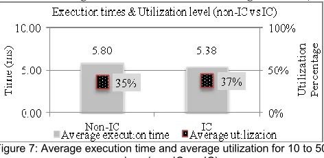
Table 1: Summary of large-scale scheduling approaches
Approach Advantages Disadvantages
Works of [8] and [29] demonstrate ELISA and MELISA that calculate the neighboring nodes load by considering job arrival rate and node loads. Jobs are transferred based on the comparison of nodes load and not queue length.
Distributed algorithm based on the centre-initiated load balancing. MELISA performs better in large scale systems compared to MELISA.
Adaptability for dynamics cannot be guaranteed and privacy issues exposed due to queues exchanging (comparison of nodes load), and virtualization capabilities are not included.
In [9], the scheduler redundantly distribute each job to multiple sites, instead of sending the job to the most lightly load though backfilling.
Increases the possibility of effective backfilling and brings better fairness.
Performs best for low loaded sites, lower overall performance for large-scale systems and no virtualization capability.
In [10], the approach connects various Condor pools which yield to a self-organizing flock of condors. It schedules jobs to idle resources by using Condor resource manager and invokes flocking mechanism only for busy machines.
It uses the Condor resource manager for scheduling to idle resources and flocks can reduce the maximum job waiting time in the queue.
Pools are characterized to suitable/not suitable; as a result unfairness will lead to starvation, also comparison of queue lengths exposes privacy issues and virtualization is not determined.
In [11], scheduling executed by site reputation and resource availability, and brokers schedule jobs through arrangements and priorities to peers where each peer can maintain ranking of all known peers.
Total decentralized solution where peers keep track of local balance for each known peer based on past interactions.
As debts grow, jobs become less prioritized, thus solution could lead to starvation. Also resources can be under-utilized due to meta-schedulers bidding for specific resources. In [13], the work temporarily binds local resources
to remote resources, when a user cannot be satisfied at the local level, through delegated matchmaking (DMM). Remote resources are added transparently.
Improved performance by reducing administrative overhead, also no local operation of central control point.
Dynamics of the system are ignored as a steady state is assumed during simulation. Also, heterogeneity and virtualization issues are not fully considered.
In [18], the target is InterGrid infrastructure where authors interlink grid islands using peering arrangements and gateways to allow a cross collaboration among various grids.
It evaluates the performance of four complex algorithms and shows an improvement in average response times.
The system dynamics may affect connections of grid islands (e.g. failures could happen during communication) and also brokers are self-interested and not global.
In [19], a meta-scheduler called GridWay sits on top of each grid infrastructure on the federated grid. Four algorithms have been developed and can be executed in the GridWay.
No requirements for information of remotes nodes and it consider past performance requirements to forecasts new objectives.
Only adoptable for specific information system as requires training mechanism for forecasting performance, also overhead during training may be increased.
In [20], a meta-broker selection process is shown for multiple grid interoperating cases. The scheduling policy consists of the bestBrokerRank policy.
Improves workloads and resource utilization as well as load balancing among different grids.
The method assumes complete and detailed resource information sharing in a stable infrastructure.
[23] shows a dynamic scheduling approach called CASA which functions as a scheduling decision to job schedule across decentralized distributed nodes.
Could lead to the same amount of executed jobs in centralized as in decentralized.
Job distribution is based on a probability to find a resource, thus requires training of the system to define probabilities.
An important characteristic of our approach is the message exchanging feature that is considered as a key requirement by most of the decentralized approaches, as reported in [9], [10], [11], [12], and [19]. However, most of these approaches do not detail the whole request-response procedure. For example, [24] suggests that mes-sages are exchanged among components in order to make cooperative scheduling decisions. Since the rejected re-sponses are returned an increased message overhead is observed. Similarly, [19] suggests an algorithm that al-lows rejected messages to return in the case a grid does not have the required slots for allocation. Authors in [10] suggest that a node that receives a message becomes aware of available resources in the pool. This includes messages that are exchanged in all the resources available in the resource pool. In contrast, [11] considers a broad-casting approach where a resource does not always re-quire to reply back. However, majority of the current per-formance optimization approaches overlook the benefits that may derive from a more fine-grained message ex-changing approach. A more detailed discussion of the message exchanging mechanisms in distributed systems is presented in [14].
3
T
HEI
NTER-C
LOUDM
ETA-S
CHEDULING(ICMS)
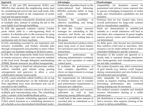
FRAMEWORKFigure 1: The three-layered structure of ICMS
Layer 3 contains a topology that involves the for-mation of low-level infrastructure and its entities such as local-brokers, data stores, hosts and VMs. It should be mentioned that our assumption is that clouds follow a standard setting (e.g. follow the open cloud computing interfaces) that includes a local resource broker that con-trols interactions with the datacenter hypervisor that in turn sandboxes it to a VM. Policies for scheduling and local resource management are implemented in the local resource broker. As shown in figure 1, the layers include the key elements of the service life cycle that are to plan, deliver and operate.
[image:5.567.31.280.547.694.2]Layer 1, the service submission management layer, is responsible to create the service configuration by translat-ing user requirements to system specification. The output is in a form that is recognized by the inter-cloud entities. Layer 2, the distributed resource management layer, col-lects service submissions and descriptions, extracts in-formation regarding performance criteria (e.g. service size) and forwards it to the appropriate execution entity. This entity could be either a local resource queue or a re-mote meta-broker that further distributes the service to interconnected brokers. Layer 3, the local resource man-agement layer, offers the service execution environment. Here, services are forwarded to the lowest level of the infrastructure (local resource management system – LRMS) and sandboxed in VMs. Prior to this, each service is queued into the LRMS queue where a scheduling algo-rithm allocates services to resources depending on the configuration of the scheduler (e.g. first come first service, shortest service first etc.). The whole ICMS is based on a group of modular policies and each of which realizes the layered structure and the dynamic requirements.
Figure 2: The ICMS modular structure
Figure 2 illustrates the configuration of the four mod-ules of the ICMS conceptual architecture, namely Service Request, Service Distribution, Service Availability and Service Allocation. Firstly, the “Service Request” module
includes the user specification and the service formation process. Each service request is recorded into a service level agreement (SLA) representation. SLAs describe ser-vice requirements e.g. serser-vice CPU etc. along with a user policy for priorities or advance reservation mechanisms for prioritized users. The “Service Distribution” module conta ins the message distribution, the meta-brokering and the SLA policy as in layer 2.
In addition, the module incorporates a mechanism for interpreting and translating the content of the SLA. The “Service Availability” module contains the SLA match-making, dynamic workload and local resource policies as in layer 3. This includes that each local-broker could de-fine the internal resource usage (by evaluating current executions) in order to decide whether this is capable to execute the service locally. Finally, the “Service Alloca-tion” module includes the hypervisor scheduler, the host allocation and VM allocation policies as in layer 4. The hypervisor is responsible for a) the sharing of host’s com-putational power between the VMs (host scheduling), b) the sharing of VM allocation of computational units (VM allocation) and c) the management of the hypervisor that queues the services in hosts.
The communication between the ICMS modules is achieved by utilizing a novel message exchanging proce-dure that allows services to be exchanged as events that are sent and received between meta-brokers by following the Message Exchanging Optimization (MEO) model [14] [26]. The assumption here is that we have a decentralized topology of meta-brokers to allow event request-response during regular time intervals. The following steps demonstrate that process.
[1] The service distribution starts when a number of services are submitted to a meta-broker. Each ser-vice request contains a set of requirements such as time intervals (e.g. waiting time, interval etc.) and computational units (CPU, memory, bandwidth, etc.). In addition, each service request includes pri-orities and advance reservation features for allow-ing specific services to be executed on specific types of resources.
[2] Each service request is stored in a list. Each list row has a message with key characteristics including the deadline and the service length as the mean for calculating resource availability on remote re-sources. The service requests are dispatched dur-ing regular intervals.
[3] The service requester defines the interval deadline, which defines a delay limit and the size of the list. For large lists the deadline could be higher as the time needed to dispatch is higher. This also con-siders the cost of communication among entities. So a small deadline results in a small number of submissions, while a large one could lead to heavy submissions. The ICMS default interval is configu-rable to meet the needs of an experiment. Further details are provided in the experimental analysis section where a detailed discussion of ICMS con-figuration is shown.
Service Request
Service Availability Service Distribution
Service Allocation
ICMS User HD and
SW data
Meta-broker policy Message exchange policy
SLA Specification
User Policy (Priority, Advance reservation)
Host
allocation allocationVM Hyper-visor
SLA match-making
Dynamic workload
Local resource data
extraction SLA
Service Request AvailabilityService DistributionService AllocationService
Event Formation
Event Collection
Event Ranking
Event Redistribution
Event Assignment [4] The service requester collects addresses of
inter-connected nodes from an internal catalogue of re-sources. These nodes are meta-brokers that are used to receive the requests dispatched from the service lists.
[5] The service requester sends a service request as a message consisting of quality of service require-ments (e.g. deadline, service length etc.). The mes-sage includes the ranking criteria (e.g. turnaround, energy consumption level); so all brokers will use the same resource selection criteria. It should be noted that identification tags define a message. During communication, the tags are set to unique values to characterize the group of messages. [6] A broker collects a single service request and
per-forms an internal resource availability check ac-cording to the ranking criterion. Then it generates a priority of services which is stored in a tempo-rary ranking list. If the list is empty, the broker cannot execute the services and it will not respond back. In any other case, the list with the ranked services is forwarded back to service requester. [7] Each service request is ranked based on a
schedul-ing function and a decision is taken accordschedul-ingly. [8] In case of service availability (each service of the
list can be executed locally) the broker generates a list with services.
[9] In case of non-availability (e.g. broker cannot exe-cute all or few of the services contained in the list) a further service distribution request will be re-performed using steps 1 to 6.
[10] In case of complete non-availability the broker will cease communication and therefore, responses are not sent back.
[11] A new list consisting of service requests which is ranked in a descending order is created. This forms the criteria for selecting services at the next re-source management level. In the case that the bro-ker acknowledges that the service request(s) will be executed on a remote machine, the broker re-directs messages to interconnected nodes. All mes-sages are assigned with updated time deadlines. [12] The ranked lists are collected from the service
quester that compares and decides whether a re-mote resource will be selected for execution or not. [13] The procedure ends and each service request is
sent to a local or remote resource.
This concludes the steps of communication, in the next section we focus on the definition of the service submis-sion and service execution features.
3.1 The definition of service submission in ICMS Let assume that there are M meta-brokers that form a decentralized inter-cloud whereM{m1,m2,...,mn}. Each meta-broker does not have a value but is associated with the name of interacted cloud. For instance cloud 1 has a meta-broker named as meta-broker1. The number n equals the number of participating clouds in an inter-cloud, thus each cloud has at least one meta-broker. Each service request is defined as ji and is assigned to a
meta-broker miand contains a number of physical characteris-tics named as CPU cpui, memory memi, cores cori
,
stor-age stori and bandwidth bwi. Each ji is a set of tuples where each request encapsulates aji=(cpui, cori, memi,stori, bwi). It should be mentioned that a service request is an IaaS encapsulation and it is defined in a similar manner to the Amazon EC2 service specification [25]. The
cpui and the cori define the clock rate as
ClockRatei=cpui*cori. It includes also the cycles per in-structions for each service named as cpiji to calculate the
required execution time. This will help us to quantify the service size in terms of traditional jobs length. Further to this, the meta-broker defines a metric to characterize each submission, e.g. the cycles per instruction (CPI) and the execution time of theji. The cpijiis defined as cpiji=cyclesji/instructionsji[6]. The execution time execji is calculated as execji=instructionsji*cpiji/ClockRateji*105. In
this paper, we also define the millions of instruction per second (mipsji) to describe an additional service length metric calculated as mipsji=ClockRateji/cpijjii*10
-6. Both
cpiji and mipsjidefine the service size with regards to the specified user submission. Each meta-broker miis as-signed with a latency latmithat defines the delay of the broker to execute a service request including the time needed for coordination and internal communication.
The total service execution time is the sum of the laten-cies of the meta-broker mi to the execution time,
TotalJobExecTimeji=Latencyji+execji. The latency of the mi
is
i m i
i Latency ComLatency
Latencym m . The ComLatencymi
de-fines the time needed to communicate with the local re-source to extract addresses for further distribution. Each meta-broker mi has a load of services and these are de-scribed as the throughput, where
i m
Troughpup is equal to the count of mi in the inter-cloud.
The ICMS calculates the utilization of mi
,
e.g the usagelevels, ( / )
i
i j
m Troughput
Troughput n
Utilizatio . For example,
the utilization of the meta-broker mi is the division of the throughput of the served jobs to the total throughput of the jobs that could be served. Finally, the service perfor-mance is described as the execution time of the VM that sandboxes the service and is calculated as
Performanceji=PerformanceVMji=1/execji
.
3.2 The algorithmic structureOur approach includes request and response entities to implement the whole set of service execution life cycle. Figure 3 shows the relationships of the algorithms. It should be mentioned that events are the steps that hap-pen in the life of cloud service requests. The process starts with the event formation and collection algorithms.
Each event algorithm (along service configurations) is then ranked and distributed in the inter-cloud. The event assignment algorithm allocates the service computational units. The structure and the relationship of the algorithms follow the sequence below. Firstly, the event collection, formation and sending procedure of the request entity takes place. This is followed by the event gathering, iden-tification of specification, ranking and response dure of a broker. Finally the event redistribution proce-dure and the event collection, ranking and assignment processes take place.
3.2.1 The event formation algorithm
The process starts with the event-formation algorithm. The ICMS sets a time interval
int
collection and a criterion for the events to be ranked at a later stage. The assump-tion is that the meta-brokers have the same uptime and are interlinked in a decentralized topology. Users submit service requests to one or many meta-brokers in an inter-cloud. During a time interval intfor a submissionwhere intincollectionthe meta-broker collects all the events including characteristics such as cpui
,
memi,cori,
stori
,
bwi,
cpiji,
ClockRatei. For alljmiit creates a list Li where each row contains the characteristics of the service request. The algorithm then sets a tag value represented ast
i
and creates the message including the Li, tiand a performance criterion. The default ICMS configura-tion includes the total service execuconfigura-tion time given
TotalJobExecTimeji=Latencyji+execji
,
the turnaround timeTurnTimecloud=(instructionsji*cpiji/ClockRateji*10
5)+Comlatency
mnand the makespan Makespanj
i=execji+Latencymn. The makespan
defines the time from start to finish, and the turnaround-time is the total execution turnaround-time of the schedule.
The algorithm opens the profile of the entity profi for i
n prof
m
it sends a message to the dedicated address. It sets an interval intdist that is the distribution interval
time. For a time timeiwhere timeiintdistcompares the tag tifor validation and collect responses by a classifica-tion funcclassifica-tion. The latter is defined by the performance criterion of the previous step. As soon as the classification event concludes the algorithm updates the list Liand sends back an msgmi only if sizeLi0
.
Algorithm 1 demonstrates the service formation algorithm. The opera-tions are defined as follows: get for the collection proce-dure of service data, set as the operation to set the re-quired service specification, create for the operation to create a list, open as the operation to open a profile, size as the method to return the size value of the profile, send as the method to send a message to an address defined as ad, run as the method to run an algorithm, wait as the method to wait for an interval to expire and update as the method to update a list.Algorithm 1: Event Formation
Require: res the requesting resource
intervalcollection: the interval time to collect service
messages
time: the current time instance i the service submitted by a source clocksi the service required clocks
CPIi the service required CPI
coresi the service required cores
bwi the service required bandwidth
hi the service required duration
Li the list with the service specification
data
tag the tag value of the message (e.g. q) msg the message contains the Li and the tag
fi the profile of the entity i
ad the address of a node included in the fi
e the tag value for incoming messages interval
distribu-tion
the interval time to collect distribution messages
response the notification of the responder criterion the performance ranking criterion
defined by the entity i
Algo-rithms: Ranking algo-rithm the event ranking algorithm that ac-cepts the criterion as an input value for service classification
Assignment
algorithm the assignment algorithm that accepts the Li as input value to determine the
next phase of resource allocation 1. set intervalcollection, criterion
2. while time < intervalcollectionwait
3. for all i
4. get(clocksi, CPIi, coresi, bwi, hi)
5. set i[clocksi, CPIi, coresi, bwi, hi]
6. create(Li[i])
7. end for
8. set tag ← q
9. create(msg[Li,tag, criterion]
10. open(fi)
11. for all fi.size()
12. ad ← get(fi[k])
13. send(msg, ad) 14. end for
15. set intervaldistribution
16. if time < intervaldistributionand
17. if tag=e then
18. get(response)
19. run(Ranking algorithm(criterion)) 20. update(Li[i])
21. end if22. for all Li.size()
22. run(Assignment algorithm(Li))
23. end for
3.2.2 The event collection algorithm
This algorithm configures an interval value for collect-ing events from the source (e.g. users) and creates a list using the incoming service request specification. Initially, the algorithm sets a termination and redistribution flag (
ftrm,fred) to recognize whether this is the termination point or the redistribution. For all
i
m msg
and ti
identifiable, it decomposes the message msgmiand collects the list Li by running the performance criterion
classifica-tion funcclassifica-tion that updates the list Li. If sizeLi0, then Li
compares the intervals of the service requester and re-sponder meta-broker. If intresintreqthen it sets the tag to an indicator for returning messages (to perform valida-tion).
The broker sends the event back to the service re-quester by sending msgmi
t
hat includes the newly formedLi. In the case of sizefi=0 it sets the ftrm flag on, else it
intercon-nected meta-brokers. In addition it characterizes the re-sponder meta-broker either as a termination point or as an intermediate node on communication. Algorithm 2 demonstrates the event collection procedure. The opera-tions are defined as follows: “decompose” for amessage decomposition operation, “get” for the collection proce-dure of service data, “rank” for the ranking procedure, “set” as the operation to set the required service specifica-tion, “update” as the method to update a list, “size” as the method to return the size value of the profile, “send” as the method to send a message to address, “terminate” as the method to terminate a message at the responder, “de-stroy” as the method to delete a list namely as Li at the responder, “open” as the method to open a profile, and finally the “run” as the method to execute an algorithm or an operation.
Algorithm 2: Event Collection
Require: i the requesting node i' the responding node
msgi the incoming message from
re-quester i flag the flag variable trm the termination flag rds the redistribution flag q the tag indication for incoming
message from requester w the tag indication for incoming
message from redistributor intresponder the interval of the responder
intrequester the interval of the requester
e the tag indication for returning messages
Algo-rithms: Ranking algo-rithm the ranking algorithm that accepts the criterion as value Redistribution
algorithm the redistribution algorithm 1. set flag←{trm, rds}
2. for all msgiand (tag=q or tag=w)
3. decompose (msgi)
4. get Li
5. run(Ranking_algorithm(criterion)) 6. update(Li)
7. if Li.size>0 then
8. if intresponder <intrequester then
9. set tag ← e 10. ad ← i 11. send(msg, ad) 12. end if
13. else
14. if fi.size=0 then
15. flag=trm 16. else then
17. flag=rds 18. end if
19. case: flag = trm 20. terminate(msgi)
21. destroy(Li)
22. case: flag = rds 23. open(fi’)
24. for all fi.size()
25. run(Redistribution algorithm(fi’))
26. end for
27. end case
28. end if
29. end for
The event collection algorithm facilitates the assembly procedure for incoming messages and the formation of the ranked list. The algorithm identifies messages for ser-vice delegation by identifying port tags (key: tag=q, for incoming message for requester and tag=w, for incoming message for further redistribution/decentralization). 3.2.3 The event ranking algorithm
The event ranking algorithm defines the criteria for service classification in the request or response from a meta-broker. To quantify such action we aim to minimize a function that calculates a set of metrics (known as rank-ings). In this paper, we define a number of parameters to calculate rankings such as: execution times, total times as well as energy consumption and service cost metrics as detailed in algorithm 3. The operation includes the size as the method to return the size value of the profile.
Algorithm 3: Event Ranking
Require: i the requesting or responding node Rank the output of the criterion instr the number of instructions cycles the number of service cycles h the uptime of the service in host dl the delay of the entity
int the interval of an entity (e.g. inti is
the interval of requester)
udl the decision making time (e.g. udly)
watts the watts of the host entity consPerKW the consumption per kW rate of the
entity
Coef the coefficient value of the entity Nomsg the total number of messages (e.g.
from entity i to y is Nomsgi:y)
1. if criterion ← ET (Execution Time) 2. Rank = instr*cycles
3. end if
4. if criterion ← TT (Total Time) 5. Rank = (instr*CPI*1/CPU)*1.cores*h 6. end if
7. if criterion ← LA (Latency) 8. Rank = dl+dli’
9. end if
10. if criterion ← DE (Degree) 11. Rank =
dli
dli'12. end if
13. if criterion ← TuT (Turnaround Time) 14. Rank = ET +LA
15. end if
16. if criterion ← MS (Makespan) 17. Rank = ET + udli’
18. end if
19. if criterion ← CPE (Consumption per entity) 20. Rank = (watts*TT*10-3)*consPerKW*coef
21. end if
22. if criterion ← CPH (Consumption per host) 23. Rank = watts *h*10-3
24. end if
25. if criterion ← MeC (Message Cost) 26. Rank = (size(Li) + size(Li’))*(1/bw)
27. end if
28. if criterion ← DeC (Delay Cost)
29. Rank = (Nomsgi:i’ +((Nomsgi’:i)/ Nomsgi:i'))/inti
30. end if
31. if criterion ← PR (Probability Cost) 32. Rank = dlentity/intentity
The degree criterion defines the degree of the decen-tralized meta-broker topology as presented in [14], [26]. In addition, we have implemented the consumption per entity cost for monitoring energy utilization (e.g. at data-centre and host level). At last, we included the cost func-tions for defining the message and delay cost.
3.2.4 The event redistribution algorithm
This algorithm describes the process of a meta-broker
mnto redistribute the event request to its interconnected meta-brokers. The message redistribution algorithm im-plements the event relocation procedure in the case of further event dissemination. The procedure alters the tag values of messages and forwards each one to a node be-longing to a personalized profile list. For all incoming
msgithat have a flag fi and fi=fredit opens the profi
and collects the address of the linked meta-brokers. It sets the tag tito an indicator q for outgoing
messag-es from redistribution. After for
i
m
j
it creates a list Liwith each row containing the characteristics of the service and creates the message msgi that includesLi
,
ti and the performance criterion. The algorithm defines an intervali
time where timeiintred
,
so during that time it sends mes-sages to other meta-brokers. Algorithm 4 demonstrates the event redistribution algorithm.Algorithm 4: Event Redistribution
Require: msg the requesting message
i the requesting or responding node msgi the incoming message from requester i
Li the list with the service specification data
fi’ the profile of the entity
flag the flag variable rds the redistribution flag
p the tag indication for outcoming message from redistributor
int the interval of the requester t the time instance
1. for all msg where flag=rds 2. open(fi’)
3. get(ad) 4. set tag ← p
5. while Rank←
o
then6. create(Li’[ji])
7. end while
8. create(msg[Li’,tag, criterion]
9. while t<intithen
10. send(msg,ad) 11. end while
12. end for
A key aspect is that the algorithm operates under the initial deadline value in order to be terminated in cases of interval violations. The algorithm allows messages to be forwarded only if there is no availability in the local re-source pool. In this case, messages are reformed and transferred to remote entities for requesting resource availability according to specific criterion.
3.2.5 The event assignment algorithm
The event assignment algorithm determines the next phase of the resource allocation. Here the events have been concluded and the service request is sandboxed in a VM. Algorithm 5 implements the allocation of services in entities (thus to their local hosts’ scheduler). The algo-rithm collects the execution results after the completion of a service request. In particular for all service requests ji
allocates each of which to the LRMS. The operations in-clude: set the tag to allocate the service to resource and the send (LRMS) to send procedure of service data into LRMS.
Algorithm 5: Service Assignment
Require: i the requesting or responding node j the service
jset the set of services in not i
a the value to define assignment
res the performance results of the service as-signment
1. for all j jset
2. set tag ← a 3. allocate (j,ad) 4. send(LRMS) 5. end for
The procedure first collects the user service request from the SLA and selects the VM allocation policy accord-ing to the LRMS specification. The default queues imple-mented in ICMS are the First Come First Served (FCFS), Shortest Service Frist (SJF), Earliest Deadline First (EDF) and Priority Scheduling (PS). For all services
LRMS
i queue
j
the hypervisor policy controls the current workload wi and calculates the total delay that includes the turnaround time and the hypervisor processing time
TotalDelay=TurnTime+hypervisorDelay. Each service jiis queued into queueLRMSby adding a keyi,jias a pair. For an
interval inti or for a specific queue length
LRMS
sizeQueue where, it schedules the service
requests and allocates host computational units based on a host allocation policy. Finally, it updates the current workload wi. This concludes the ICMS description.
4
S
IMULATING THEI
NTER-C
LOUD(S
IMIC)
T
OOLKIT This section illustrates the description of SimIC v2.0 (Simulating the Inter-Cloud version 2) that is a novel simulator used to implement the inter-cloud functionali-ty. SimIC is a discrete event simulation toolkit based on the process oriented simulation package of SimJava [16]. SimIC is used to simulate an inter-cloud facility where multiple clouds collaborate for service request distribu-tion in a simuladistribu-tion setup. The package encompasses the ICMS algorithms including users, meta-brokers, local-brokers, datacenters, hosts, hypervisors and virtual ma-chines (VMs). In SimIC, the message initialization begins at time instance 1, and then a message is created at state 1. After this, state 2 collects the message (get from out port State 1) and sends the message to in port State 3. During this time, the instance passes from time 2 to 3 and finally to time instance 4. Finally, the message is terminated (or initialized) from another state in order to continue the information exchanging. A more detailed discussion of the tool is presented in [16] that illustrate the layered structure of the tool and internal processes.4.1 The SimIC technical features
4.2 The SimIC layered Architecture
The entities and their functionality are organized in a three-layer structure. This includes the entity layer, the queuing, behaviour and tagging layer, and the perfor-mance and tracing layer. Specifically, Layer 1 includes the entities representing the objects of the system. In a SimJa-va simulation, each feature is represented by a sim_entity class that encapsulates the core functionality. Each SimIC class defines the actual behaviour (layer 2) of entities that are the ICMS resources. The core classes are User, Meta-broker, Local-Meta-broker, Datacenter, Hypervisor, Hosts, VMs and Bucket. The initialization process begins when a user starts communication with the meta-broker through a user interface. Like a meta-scheduling system. The latter acts on behalf of the user and forwards the request to low level resources (either local or remote sites). This proce-dure is executed by a local-broker.
Layer 2 represents the core features of SimIC including the utilization of ports, functionalities and constraints that demonstrate the actual behaviour of the system entities. Each class contains at least one port for input or output messages to other linked entities. In addition, it incorpo-rates mechanisms for collecting messages, taking deci-sions (based on policies) and forwarding to an entity for request delegation and execution. Each entity is defined by constraints to govern its actions. The actual communi-cation is based on the tags that are assigned to messages during exchange. These tags are the means of identifying the origin of a message and the operations expected from a responder. Additionally, queuing refers to the orches-tration of events (that are service messages) according to different LRMS (FCFS, SJF, PS).
Layer 3 relates to the performance monitoring and tracing operations of the system entities. The performance measures include execution time of the VM, turnaround time of service, makespan of the service, throughput of services in an entity, host utilization levels, VM utilization levels, service latencies and VM uptime times. Most of these metrics could be utilized by different entities in or-der to measure the performance of SimIC at different in-stances, for example throughput of a datacentre or latency at a hypervisor.
4.3 The SimIC entities
SimIC automates service request distribution among decentralized meta-brokers. Meta-brokers are placed on top of each cloud in order to communicate with other brokers to produce a distributed and interoperable cloud infrastructure (similar to grid computing). In SimIC each request is treated as unique. For example, a user requests for a VM, suppose with 0.25 of 1 host performance and executes a set of programs with 100*106 instructions, and CPI (cycles per instructions) of 3 (300 cycles /100 instruc-tions) in a machine with clock rate of 1000 MHz (0.25 of 4000MHz of Host with single core). The performance in-dicators of the VM are calculated as follows. The
execu-tion time is given by
cores cpu
CPI n Instructio
ExecTimeVM 1/ 1/ . Thus, the
result is calculated as follows:
ms ns
ExecTimeVM 100 10 3 1/1000 1 3 10 0.3
5
6
.
The performance of the VM is calculated at 3.33 based on
PerformanceVM=1/ExecTimeVM=3.33. Next, we present a description of the SimIC entities that implement ICMS functionality.
The UserCharacteristics class instantiates the service in-formation for each of the users by incorporating hard-ware and softhard-ware requirements that has been previously defined in two different files. Each service jiis assigned
to a meta-broker mi. It contains a number of physical characteristics named as CPU cpui, memory memi, cores
cori
,
storage storiand bandwidth bwi.
The ServiceCharac-teristics class calculates an initial performance request based on the performance estimation that is calculated by the number of MIPS as given by the formula6
10 /CPI
ClockRate . The OutputUserRequirements class gen-erates a dynamic user profile that includes a variety of hardware, software (heterogeneous requirements) and initial performance request measurements.
The User class is responsible in forwarding requests ( namely asjmi)to resources, wherein each request is scheduled after a specific processing delay to a dedicated meta-broker. The Meta-broker class implements the in-teroperability functionality of SimIC (M{m1,m2,...,mn}).
Specifically, each meta-broker is interconnected with one or more meta-brokers depending on a simulation experi-ment. The Bucket class represents the terminal entity that collects the unexecuted services and keeps logs related to services. These could be either re-directed to an inter-cloud after a regular interval or terminated if there is an SLA mismatching. Termination and re-distribution flags (
ftrm,fred) are used to decide whether this is the termina-tion or the re-distributermina-tion point.
The local-broker (that is the internal cloud broker) class defines an SLA matchmaking process for deciding whether the specification of user requirements could be addressed by a local resource. The datacentre’s current performance is dynamically calculated for measuring the available computational power. This is realized by a mes-saging policy, as for all
msg
miand thetiis identifiable, the algorithm decomposes the message msgmiand collects the list Liby running the performance criterion classifica-tion funcclassifica-tion that updates the list Li. This includes the validation process of tag ti. The OpenHost class imports each host characteristic from a file by allowing SimIC to access host hardware characteristics while OpenHostsList opens a list from a file that contains the individual hosts dedicated to a specific cloud.The Datacenter class accepts events for VMs deploy-ment in the cloud that are determined by a hypervisor. This class implements functionality for calculating costs and energy consumption. It passes all events to a local policy enforcement engine. The Hyper class represents a hypervisor and is responsible for collecting requests for VMs from the datacenter class by accessing the host and VM allocation policies. This class queues each service ji
The HostCharacteristics class imports each specific host computational capacity as defined in a file. The Hosts
class represents a static computing machine. The class gets an event from Hyper for requesting an instance of the host characteristics. Eventually, this adds an addition-al delay to the hypervisor decision making process when allocating a VM. This is the latency of the host for starting the service execution. The VM class sandboxes the user profile. A more detailed discussion of the SimIC imple-mentation is presented in [16].
To calculate the total communication delay of messag-es we split the latencimessag-es incurred at different stagmessag-es of a service request execution life cycle in an inter-cloud. Thus, let’s assume that a number of entities E with
E={e1,e2,...,en}are linked as a directed graph to form a
topology in an inter-cloud. For each communication a message msgiis sent containing the service requirements
jiand a tag tagi. The assumption is that a trail is generated from one entity to another in such a way that the weight of the trail we1:wenis calculated as the latency of the message msgito reach entity en. The cumulative latency of the user to VM communication is calculated as
follows:
E mbr
i mrb
i
bro meta
Latency deg( ker)
,
i
i E
dc i
dc dc dc coef
Latency
i
i 2 deg( ) deg( ))
1
( thus,
Latencyuser-vm=Latencymbi+Latencydci+Latencyhyperi
So, for each message msgi that is sent from entity e1 to
en, the messaging factor (MF) defines a metric for the cost of message distribution. In a bi-directional graph for-mation this is calculated as the division of the sum of the messages received by the sum of the messaged sent as
0 0
/
j i j
j
msg
msg
MF
where msgi{msg1,msg2,...,msgn}, msgj{msg1,msg2,...,msgj} and Li0. Here
repre-sents the maximum number of requested messages and [image:11.567.286.531.396.494.2]is the maximum number of received messages. To con-clude, this section presented SimIC, a toolkit that allows system architects to configure a variety of inter-clouds in terms of entities and policies. The toolkit contains a num-ber of scheduling algorithms and features for achieving configurable service execution.
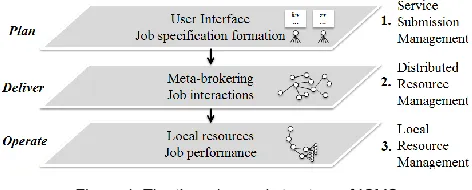
Figure 4: Description diagram of the SimIC entities Performance evaluation
Figure 4 demonstrates the various actors and the inter-actions among the SimIC entities. A more detailed
discus-sion and explanations of the various entities along with their relationships are presented in [16]. Next section demonstrates an experimental analysis and evaluation of the ICMS.
5
P
ERFORMANCEE
VALUATIONThe experimental setup implements the messaging proach of [14] and involves the comparison of two ap-proaches, namely a centralized inter-cloud (IC) and the decentralized ICMS model of inter-cloud being followed in this paper. In centralized approach the assumption is that there is a bi-directional communication among all nodes in a cloud. In this approach, we first focus on demonstrating that there is no experimental bias. We achieve this by running a number of tests, which show that a centralized IC does not affect cloud performance. Then we configure an ICMS based IC for service execu-tions which is similar to the centralized setup. Finally, we show performance analysis of ICMS considering service request arrivals and load distributions in both static and dynamic modes. Our experimental results show that ICMS with dynamic workload management outperforms static mode when all resources are available. Our simula-tions implement the next experimental setting where 5 users submit requests in cycles, as it is shown in table 2. The hosts specification includes a total of 166 cores per cloud with an average of 103 MHz CPU, 10 GB RAM, 104 GB storage and 10 mbps bandwidth per host.
Table 2: The SimIC configuration
Username StS MaL OlS NiS NiB
Memory 4000 6000 2000 2000 8000
CPU-cores 4 4 2 2 4
CPU-speed 4000 4000 2000 2000 10000 Storage-HD 10000 10000 10000 10000 10000 BW 10000 10000 5000 10000 10000 Instructions 10*108 12*108 15*108 16*108 16*108
CPI 1 4 3 3 3
5.1 Cloud vs. inter-cloud settings
The first experiment aims to demonstrate that IC does not affect performance of a cloud, thus we compare with a similar hardware setup. We show that IC performs bet-ter than or equal to non-IC setting where both cases have exactly the same computational capacity. This means that a cloud that is non-IC based has exactly the same capacity (CPU, memory, storage and bandwidth) as with an IC based cloud that is made from two clouds, cloud 1 and cloud 2. The experimental analysis involves constant submissions of intervals of 2ms. Cloud 1 includes 5 users that submit 10 to 50 service requests. Each time a request arrives in the hypervisor, a new VM is generated accord-ing to the available resources.
In both cases (cloud and IC) the utilization model of [5] is applied. This involves that resources will be allocat-ed if they are available until the utilization reaches its peak (100%). IC distributes the jobs based on the MEO and centralized distribution approaches as discussed in [14]. In both cases (cloud and IC) all services are executed in local clouds, as there is no option for further service distribution. As the number of service requests increases, the IC will increase the makespan value due to the latency
User Data
User
Service Data
Meta-Brokera
Local-Brokera
Meta-Brokerb
Datacentera VMs
Hosts
[image:11.567.47.257.608.708.2](set to 2ms) that is caused by the message exchanges. In particular, the study sets this value to a low number (2ms) as the assumption is that cloud 1 divided over two.
[image:12.567.38.278.106.223.2]Figure 5: Makespan for 10 to 50 services (non-IC vs. IC) Figure 5 shows the makespan values for 10 to 50 ser-vice requests per user to each cloud. Both trend lines show similar variations, which means that non-IC and IC follow similar makespan trends. Figure 6 shows the exe-cution times (10 to 50 services) for both IC and non-IC cases.
Figure 6: Execution times for 10 to 50 services (non-IC vs. IC) The average execution time for a single service request in the non-IC case is 5.79ms while for IC case is 5.38ms. This shows that IC achieves better execution time due to the better allocation of the resources. The improvement of IC is calculated at 7% (percentage of the division of the difference of higher to lower value, to the higher value).
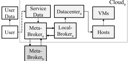
Figure 7: Average execution time and average utilization for 10 to 50 services (non-IC vs. IC)
Figure 7 shows the average execution time and average utilization rates for both cases. It indicates that the aver-age utilization of the IC case is 37.2% and the non-IC case is 35.4%. The average execution time shows decreasing value for the IC case. To conclude, IC increases utilization levels because it executes more service requests by de-creasing the IC average execution times. The values are calculated based on the formulas of section 3.1 and is re-lated to the throughput value of services. In detail, the values are relatively low due to the low number of service requests with respect to the cloud resources.
5.2 The inter-cloud vs. ICMS setting (1 service request submission per cloud)
We present two cases for 1 and 50 user submissions per cloud and we monitor the performance in both cases. The experiment demonstrates that ICMS performs better than or equal to the IC setting (with augmented datacen-ter view) with both having the same host configuration (5 clouds). This increase in performance is due to the service distribution and meta-scheduling approach being fol-lowed in the ICMS framework. In IC each meta-broker has a complete knowledge of the actual cloud infrastruc-ture (e.g. datacenter characteristics, Hosts, VMs) as it communicates with other cloud brokers for information exchange. In contrast, the ICMS approach has a partial knowledge of the infrastructure and follows the decen-tralized message distribution as it is discussed in [14]. This offers a higher level of abstraction for the entire cloud because a set of users are only mapped to a restrict-ed set of meta-brokers at a time.
5.2.1 The inter-cloud vs. ICMS setting for 1 service submission per cloud
[image:12.567.39.278.307.420.2]The experiment includes an IC of 5 clouds that have the same host specification with the ICMS and the topol-ogy is considered as decentralized. Specifically we first assume that each cloud meta-broker can access the next in the list. For example, meta-broker 1 sends a service re-quest to meta-broker 2, then meta-broker 2 to meta-broker 3, etc. For each service request that is submitted, if cannot be executed in the local cloud, it is always forwarded to remote cloud(s). The availability is set so that each service can be executed in the next cloud (e.g. service 1 to cloud 2, service 2 to cloud 3 etc.). In the centralized case (IC) the assumption is that all clouds can access all other clouds directly. Figure 8 shows the makespan times for 1 service submission per user with 1ms interval.
[image:12.567.294.537.477.567.2] [image:12.567.41.277.500.615.2]as the difference of the highest value of the metric from the lowest value of the same metric divided with the highest value e.g. (xy)/x100%when x and y repre-sent
latency
uservm.Figure 9: Comparison of performance (response ratios) of ICMS-IC The figure shows that the performance increases for ICMS as more users submit requests in a linear manner. Yet as requests are transferred to remote clouds (e.g. cloud 2, cloud 3 etc.) the ICMS performance decreases with regards to the performance as in the original ICMS setup.
5.2.2 The inter-cloud vs. ICMS setting for 50 service submissions per cloud
This experiment demonstrates the simulation results for high workload submissions (50) per user. As more services are exchanged resource availability becomes more limited and allocation management becomes more complex. In order for the results to be comparable the study takes into account clouds with exactly the same utilization levels (e.g. for this experiment clouds 3 and 4 offer the same utilization of 20% and clouds 2 and 5 with utilization of 6%). Services that cannot be executed due to non-resource availability or SLA mismatching are dropped, as the dynamic workload is inactive. This means that we do not re-schedule jobs to resources.
Figure 10: Makespan times for 50 services per user for clouds with same utilization (clouds 3, 4)
Figure 10 shows that the makespan times for 50 ser-vices per user have slightly improved results for ICMS and clouds 3 and 4 (same utilization levels). The average makespan time for IC (clouds 3 and 4) is 639706ms while the same metric value for ICMS (clouds 3 and 4) is 638806ms (900ms difference). Figure 11 shows the makespan for clouds with low utilization of 6% (clouds 2, 5). Again, ICMS algorithms offer lower makespan times when compared to IC. To conclude, both cases (1 and 50 users) show that the ICMS achieves better makespan and turnaround times. This will affect the resource utilization and resource usage as the total scheduling and execution time of services is reduced.
Figure 11: Makespan times for 50 services per user for clouds with same utilization of 6% (clouds 2, 5)
5.3 The ICMS setting: low and high delays and 40% to 100% resource availability
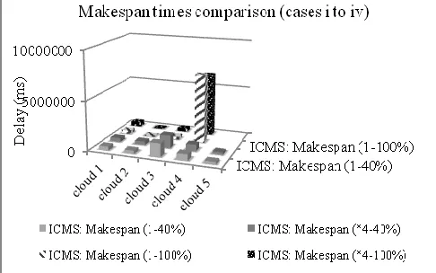
This experiment demonstrates the dynamic workload management for an ICMS case. The decentralized ICMS sends service requests to different clouds by incorporat-ing dynamic distribution. This experiment executes re-quests having a combination of 1ms to 4ms delay and 40% to 100% resource availability. The percentage is re-lated to the ability of a cloud to execute the specific ser-vice task; e.g. the 40% availability is selected as it demon-strates a cloud with low resource availability. The next list is a mixture of different combinations in the experiment.
(i) 1-40%: delay 1ms, availability 40%
(ii) *4-40%: delay 4ms, availability 40% (where * indi-cates that delay is 4 times higher than case i) (iii) 1-100%: delay 1ms, availability 100%
[image:13.567.31.278.105.203.2](iv) *4-100%: delay 4ms, availability 100% (where * in-dicates that delay is 4 times higher than case iii) Figure 12 shows the makespan times of ICMS for each of the four cases. It is shown that when the availability is 40% ICMS distributes service requests to all clouds; how-ever in the case of 100% availability, cloud 4 executes most of the service requests. This is because of the high number of hosts that are available in cloud 4, which in-crease the available computational power.
Figure 12: Makespan times for ICMS cases
[image:13.567.36.276.443.553.2] [image:13.567.287.530.454.606.2]