N A N O E X P R E S S
Evolution of ZnS Nanoparticles via Facile CTAB Aqueous
Micellar Solution Route: A Study on Controlling Parameters
S. K. MehtaÆSanjay KumarÆ Savita ChaudharyÆ K. K. BhasinÆ Michael Gradzielski
Received: 11 August 2008 / Accepted: 17 October 2008 / Published online: 6 November 2008
Óto the authors 2008
Abstract Synthesis of semiconductor nanoparticles with new photophysical properties is an area of special interest. Here, we report synthesis of ZnS nanoparticles in aqueous micellar solution of Cetyltrimethylammonium bromide (CTAB). The size of ZnS nanodispersions in aqueous micellar solution has been calculated using UV-vis spec-troscopy, XRD, SAXS, and TEM measurements. The nanoparticles are found to be polydispersed in the size range 6–15 nm. Surface passivation by surfactant mole-cules has been studied using FTIR and fluorescence spectroscopy. The nanoparticles have been better stabilized using CTAB concentration above 1 mM. Furthermore, room temperature absorption and fluorescence emission of powdered ZnS nanoparticles after redispersion in water have also been investigated and compared with that in aqueous micellar solution. Time-dependent absorption behavior reveals that the formation of ZnS nanoparticles depends on CTAB concentration and was complete within 25 min.
Keywords ZnS nanoparticles Optical absorption XRDSAXSFTIR-spectroscopy
Introduction
There has been great interest over the years to improve the fundamental understanding of CTAB aqueous micellar system. However, some aspects particularly the factors controlling synthesis of nanomaterial in aqueous solution of surfactant are still not very well understood. Further efforts are being made to control the shape and size of nanoparticles using surfactant aggregates. Unfortunately, the use of surfactant monomers/assemblies to control the shape and size of nanoparticles remains an extremely difficult task, since the surfactant adsorption and aggre-gation processes itself is affected by many kinetic and thermodynamic factors. These factors will have an obvi-ous effect on nanoparticles synthesis in aqueobvi-ous micellar media. Increasingly, chemists are contributing to under-stand the synthesis, mechanism, and novel properties of semiconductor nanoparticles using various surfactants. Of the various type of nanocrystals, semiconducting metal chalcogenide nanocrystals have been most intensive studied because of their interesting effects such as size quantization [1, 2], non-linear optical behavior [3], pho-toluminescence [4], and so on. The increase in band gap with decrease in particles size is the most identified aspect of quantum confinement in semiconductors. ZnS is a wide band gap semiconductor with band gap energy (Eg) of
3.68 eV. It has been widely used in many optoelectronic devices such as blue-light-emitting diode, solar cells, and field emission devices [5–7]. Their synthesis has been achieved via various routes, including hydrothermal syn-thesis, aqueous micelles, reverse micelles, sol–gel process, and spray pyrolysis [8–12].
Considerable experimental work has been performed in the past in order to synthesize and understand the prop-erties of ZnS nanoparticles with and without using
S. K. Mehta (&)S. KumarS. ChaudharyK. K. Bhasin Department of Chemistry and Centre for Advanced Studies in Chemistry, Panjab University, Chandigarh 160014, India e-mail: [email protected]
M. Gradzielski
Stranski-Laboratorium fu¨r Physikalische Chemie und Theoretische Chemie, Institut fu¨r Chemie, TU Berlin,
surfactants [13–15]. Cao et al. [9] synthesized ZnS nanotubes taking CS2 as sulfide ions source at high
temperature and using Triton X-100 as micellar template. Wu et al. [16] obtained winding ZnS nanowires from reverse micelle solution. Mitra et al. [17] prepared ZnS nanoparticles in aqueous solution of anionic surfactant, sodium dodecylsulfate (SDS), and studied the effect of surfactant only at concentrations above critical micellar concentration of SDS. To synthesize nanoparticles with well-defined shapes and sizes, detailed understanding of stabilization mechanism and controlling parameters is required. Furthermore, one of the typical features of nanoparticles is their spontaneous self-aggregation into functional structures driven by the energetics of the sys-tem, which are known as self-aggregated nanostructures. Though in solution the nanoparticles may be well sepa-rated, during separation process, some of the particles may get agglomerated. Thus, the effectiveness of any synthetic method can be defined in terms of the per-centage of particles obtained within the required size range and extent of self-agglomeration during separation process. There are only few reports [18,19] on systematic investigations of ZnS nanoparticles using CTAB aqueous micellar media that provides detailed understanding of stabilization mechanism. It is well established in literature [20] that the rate of adsorption of cationic surfactants is very fast and the final amount adsorbed is higher than anionic and non-ionic surfactants. Therefore, if adsorption is thought to be the criteria for the stabilization of nanoparticles, then size, shape, and other properties of the nanoparticles in cationic surfactant like CTAB must differ from those in anionic and non-ionic surfactants.
Keeping the above points in view, we report the results related to various parameters controlling the synthesis and stabilization of ZnS nanoparticles in aqueous solution of CTAB. In addition to other characterization techniques, time-dependent absorption behavior has been used to investigate the effect of surfactant on nanoparticles growth process.
Experimental
Synthesis of CTAB-Capped ZnS Nanoparticles
Cetyltrimethylammonium bromide (CTAB, sigma, 99%), Zn(OAc)22H2O (CDH, 99.5%), Na2SxH2O (CDH,
55–58% assay) all analytical grade have been used as received. Aqueous solution of CTAB, Zn(OAc)22H2O
(0.025 M), and Na2S xH2O (0.025 M) was prepared in
double distilled water. The aqueous solution of CTAB
was stable for months together except at temperature below 288.15 K. ZnS nanoparticles were prepared using simple precipitation method described by Han et al.[18] with some modifications. In the typical procedure, the CTAB micellar solution containing Na2S was added
dropwise to another containing Zn(OAc)2 with constant
stirring in a thermostated vessel maintained at 298.15 K. The solution was then allowed to stand for 30 min at the same temperature. The concentrations of both the salts in aqueous micellar solution were varied between 0.1 and 0.7 mM. The nanoparticles in aqueous micellar media were then subjected to UV-vis, SAXS, fluorescence, and TEM measurements. The ZnS nanoparticles were sepa-rated from solution by slow evaporation of solvent at 50– 55°C. The particles were isolated, washed with water and ethanol, and then again dried at 50–55 °C. The dried powder was collected and subjected to XRD, SEM, and FTIR measurements. The material was redispersed in water to again perform TEM, fluorescence, and absorption measurements.
Characterization of Nanoparticles
Results and Discussion
Formation and Optical Properties of ZnS Nanoparticles All the components (Zinc acetate, Sodium sulfide, CTAB) of the system are ionic; therefore, in aqueous solution the concentration of individual ion can be taken as the con-centration of the salt itself. The ionic reaction could be expressed as
Zn2þð Þ þaq S2ð Þ !aq CTABZnS Sð Þ
Theoretically, the ratio [Zn(OAc)2]:[Na2S] would be 1:1.
But actually [S2-]\[Na2S], because aqueous solution of
Na2S contained both aqueous H2S and HS-as well as other
sulfur oxyions such as thiosulfate and sulfite, originating either as impurities in solid Na2S or from rapid oxidation of
HS-by O2 [21]. Thus, some preliminary experiments of
ZnS nanoparticles formation in aqueous solution of CTAB were undertaken to develop an understanding of the [Zn(OAc)2]:[Na2S] ratio, which leads to the formation of
maximum ZnS nanoparticles.
Figure1a shows UV-visible spectra of ZnS nanodi-spersions at different [Zn(OAc)2]:[Na2S] ratios with
constant [Zn(OAc)2] and varying the [Na2S]. The aqueous
solution of CTAB and zinc acetate shows no distinctive absorption in 200–500 nm range, whereas aqueous Na2S
shows a prominent peak at 229 nm. The UV-visible spectra of reaction solutions containing Zn2?and S2-in aqueous CTAB show a characteristic absorption shoulder in 292– 297 nm region with disappearance of peak at 229 nm. This can be regarded as exiton peak for ZnS nanocrystals and proves the existence of ZnS nanoparticles [22]. The
absorbance increases with increase in [Na2S] and is
max-imum at [Zn(OAc)2]:[Na2S]=1:2 revealing that the
formation of ZnS nanoparticles is maximum at this ratio. The absorbance at [Zn(OAc)2]:[Na2S] =1:3 remains the
same, but the shoulder is red shifted due to increase in the size of nanoparticles. Thus, the ratio [Zn(OAc)2]:
[Na2S]=1:2 was found to be most suitable for further
studies. Also, it was noted that the absorption shoulder remained unchanged for several months and no precipita-tion occurred, indicating good stability of ZnS nanoparticles in aqueous surfactant solution of CTAB. It was further observed that there is no direct evidence of a particular CTAB concentration can be defined that can stabilize a given ZnS concentration. [ZnS]=1 mM in [CTAB]=5 mM was stable for months together, whereas [ZnS]=2 mM in [CTAB]=10 mM got precipitated within a day. However, the ZnS nanodispersion was stable for a week at a very high CTAB concentration (0.3 M). Some representative UV-visible spectra of ZnS nanodi-spersion in 1.5 mM aqueous CTAB as a function of salt concentration (0.1–0.7 mM) are shown in Fig.1b. Obvi-ously, the increase in intensities of absorption shoulder with increasing salt concentration reflects formation of more ZnS nanoparticles. The increase in absorbance fol-lows Lambert-beer law atkmax=294 nm, suggesting that
the formation of nanoparticles depends exactly on salt concentration keeping the temperature and CTAB con-centration constant (Fig.1c).
It is a well-established fact that as a consequence of quantum confinement of photogenerated electron-hole pair, the UV-vis absorption spectra of semiconductor quantum dots is size dependent [23]. It is also noteworthy in this
250 300 350
0.0 0.5 1.0 1.5 2.0 2.5 3.0
(a)
4
1
[Zn(OAc)2]:[Na2S]
[CTAB] = 2mM [ZnS] = 0.5mM
ε
0
1
x
3
l
o
m
L(
1-m
c
1- )
).
u.
a(
e
c
n
a
br
o
s
b
A
Wavelength (nm)
250 300 350
0.0 0.5 1.0 1.5 2.0 2.5
(b)
7
1 [ZnS]
[CTAB] = 15x10-4M
Wavelength (nm)
0.0 0.2 0.4 0.6 0.8
0.0 0.2 0.4 0.6 0.8 1.0
(c)
[ZnS] mM
0.90 0.95 1.00 1.05 1.10 1.15 1.20 1.25 1.30
λMax= 294nm
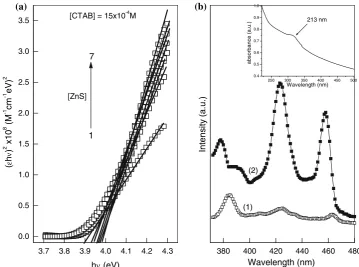
Fig. 1 (a) UV-visible spectra of ZnS nanoparticles at different [Zn(OAc)2]:[Na2S] ratios. [Zn(OAc)2]:[Na2S] : (1) 1:1, (2) 1:1.5, (3) 1:2, (4) 1:3. (b) UV-vis absorption spectra of ZnS nanoparticles at different concentrations in 1.5 mM aqueous CTAB. [ZnS]:
[image:3.595.87.510.476.667.2]work that the absorption shoulder is red shifted with increase in salt concentration. This shows that particles size increases with increase in salt concentration; however, the size distribution is different depending on the salt and surfactant concentration and hence average particles size may not follow increasing trend. Furthermore, the lack of clearly resolved peak in UV-visible spectrum shows that a range of particles above size 5 nm were formed regardless of concentration of salt and surfactant [24]. These obser-vations are in agreement with TEM studies, which show nearly monodispered particles with size in the range of 6 to 15 nm. The overall effect was reflected in an increase in molar absorbance with increase in salt concentration at
kmax=294 nm (Fig.1c). This increase can be attributed to
the fact that ZnS dispersions approach a size that strongly absorbs at 294 nm. The optical band gap of ZnS nano-particles has been evaluated from the absorption spectrum using the Tauc relation [25]
ehm
ð Þ ¼C hmEg
n
ð1Þ whereCis a constant,eis the molar extinction coefficient, Egis the average band gap of the material andndepends on
the type of transition. The value of molar extinction coefficient for the synthesized nanoparticles is more than 900; thus, we can assume that the transitions in the nanocrystals are allowed direct transitions. Forn=,Eg
in Eq.1 is the direct allowed band gap. The average band gap was estimated from the linear portion of the (ehm)2vs. hmplots (Fig. 2a) and was found to decrease with increase
in [ZnS]. The band gap values were higher than the value of bulk ZnS (3.68 eV) due to quantum confinement of ZnS nanoparticles. The average particle size of ZnS nanoparticles was determined using Wang equation [26] Eg ¼ E2þ2Eh2ð1=dabsÞ2=m
h i1=2
ð2Þ whereEgis the energy gap of ZnS nanoparticles,Eis the
band gap of bulk ZnS, and dabs is the diameter of
nanoparticles. The effective massm*is defined as
1=m¼1=2 1=mð eþ1=mhÞ ð3Þ
wheremeis mass of electron andmhis mass of hole. For
ZnS, me and mhare reported to be 0.34 m0, and 0.23 m0
respectively, m0being the rest mass of electron [17]. The
band gap values and corresponding average particle size are listed in Table1. The average particle size calculated is found to be smaller than that estimated from SAXS. This discrepancy in particle size is due to some approximations involved in the calculations, and neglecting the term containing permittivity in the Wang equation [27]
3.7 3.8 3.9 4.0 4.1 4.2 4.3 0.0
0.5 1.0 1.5 2.0 2.5 3.0 3.5
(a)
[CTAB] = 15x10-4M
[ZnS] 7
1
(
ε
h
ν
)
2
0
1
x
8 M(
1-m
c
1-)
V
e
2
hν (eV)
380 400 420 440 460 480 Wavelength (nm)
).
u.
a(
e
c
n
a
br
o
s
b
a
213 nm
Wavelength (nm)
).
u.
a(
yti
s
n
et
nI
(b)
(2)
(1)
250 300 350 400 450 500 0.4
0.5 0.6 0.7 0.8 0.9 1.0 Fig. 2 (a) Tauc plots for the
[image:4.595.182.542.58.325.2]determination of optical band gap of ZnS nanoparticles prepared in 1.5 mM aqueous CTAB. [ZnS]: (1) 0.1 mM, (2) 0.2 mM, (3) 0.3 mM, (4) 0.4 mM, (5) 0.5 mM, (6) 0.6 mM, (7) 0.7 mM. (b) Photoluminescence spectra of ZnS nanoparticles in (1) aqueous micellar solution (2) redispersed in water. Inset shows absorption spectrum of ZnS nanoparticles (0.5 mM) redispersed in water
Table 1 Optical band gap (Eg) and nanoparticle diameter (dabs) as calculated from tauc plots and Wang equation
[ZnS]/mM 0.1 0.2 0.3 0.4 0.5 0.6 0.7
Eg/eV 3.88 3.93 3.97 3.95 3.94 3.99 3.96
[image:4.595.306.545.666.714.2]Eg¼Eþ h2p2=2R2
1=meþ1=mh
ð Þ 1:786e2=pR ð4Þ whereR=dabs/2,pis the permittivity of nano ZnS and rest
parameters have already been defined. Furthermore it is clear from Fig.1b that the shape of UV-absorption curves is the same irrespective of [ZnS]. Therefore, UV-vis studies reveal that the average size and shape of nanoparticles in CTAB are independent of [ZnS] due to different size dis-tributions. However, Mitra et al. [17] demonstrated that ZnS nanoparticles size increases with [ZnS] in aqueous micellar solution of anionic surfactant, SDS.
Photoluminescence (PL) Studies
Figure2b compares the room temperature PL spectra of the ZnS nanocrystals in aqueous micellar solution and that of ZnS nanopowder redispersed in water. In both the measurements excitation wavelength was 320 nm. The ZnS nanocrystals in aqueous micellar solution of CTAB exhibit three emissions peaking at 383, 424 and 462 nm, and redispersed ZnS shows two intense emissions at 424 and 462 nm and one weak emission at 380 nm. The interesting point is that the intensity shows reciprocal trends in two samples, i.e., the emissions that are strong in one become weak in the other and vice versa.
This type of behavior can be attributed to change in shape and size of nanocrystals during separation and drying process as the luminescence spectra show size- and shape-dependent quantum confinement effects. In literature, the emissions at*383 and at*423 nm have been assigned to shallow-trap and deep-trap emissions or defect-related emission of ZnS, respectively [28,29]. Han et al.[18] have also observed similar type of defect-related emissions near 430 nm for CTAB passivated ZnS. The change in intensity of these emissions can be explained in terms of surface passivation by sulfide ions and surfactant molecules and unpassivation during separation and drying process [30]. The nanocrystals in aqueous micellar solution are surface passivated by excess sulfide ions and surfactant monomers and show weak deep-trap (intense shallow-trap) emission, whereas due to removal of passivation after redispersion the defect-related emission (423 nm) became more intense due to defects in nanocrystals. The peak at*462 nm has been assigned to the presence of sulfur vacancies in the lattice [31]. ZnS nanocrystals contain excess of sulfur in aqueous micellar solution, and thus show weak emission due to sulfur vacancies, but the emission became intense when excess of sulfur has been removed from the redi-spersed sample.
The agglomeration behavior of nanoparticles during separation and drying process has also been studied by calculating the size of nanoparticles by performing UV-vis, XRD, and SEM measurements on dried samples. The inset
in Fig.2b shows the absorption spectrum of powdered ZnS nanocrystals redispersed in water. A minor absorption shoulder peaking at 313 nm (3.96 eV) is observed. The particle size corresponding to this peak was calculated to be 6.7 nm. However, the particles seem to be much agglomerated in the powder form as evident from SEM micrographs (discussed in subsequent section). From these observations, we can infer that during drying process par-ticles get agglomerated to some extent, but the parpar-ticles have good tendency of redispersion in water.
TEM and SEM Analysis
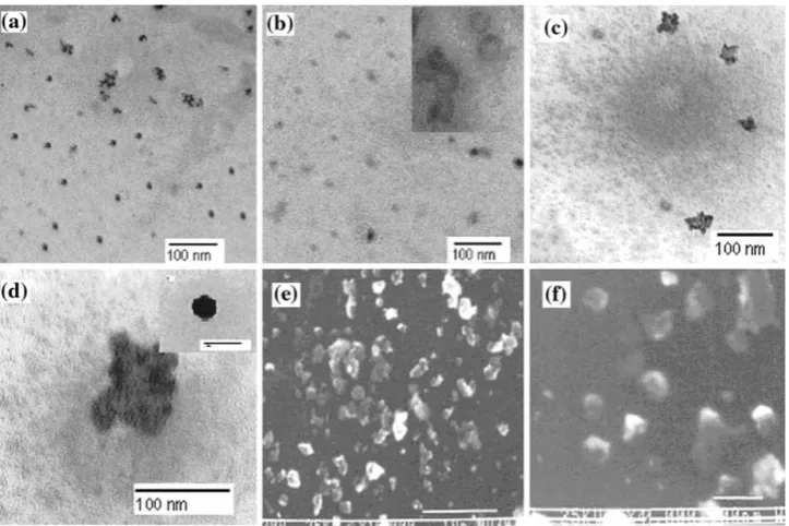
Transmission electron microscopy (TEM) has been per-formed to assess the size and morphology of the particles. The TEM micrographs of ZnS in aqueous CTAB solution with different concentrations are depicted in Fig.3. In Fig.3a, nearly spherical and well-separated particles are evidenced with few agglomerates. The agglomeration was probably because the particles in a concentrated sample could end up in association during grid drying in the TEM sample processing protocol [32]. The spherical shape of particles is also evidenced from the inset of Fig.3b, which presents magnified view of nanoparticles.
Figure3c, d shows the typical TEM images of the product redispersed in water and powdered sample, respectively. Nanoparticle aggregates are clearly visible in TEM micrograph. The magnified view of such an aggre-gate containing 8–10 particles is shown in Fig.3d. By randomly measuring over 40 such clusters, we confirmed the size to be 6–15 nm with a few particles having a size more than 15 nm but less than 60 nm. However, most of the particles have the size 4–10 nm. The spherical mor-phology of synthesized particles is clearly displayed in the inset of Fig.3d, which shows fully grown single particle. A typical low magnification SEM image of the powdered sample is shown in Fig. 3e revealing some spherical nanoparticles with most of the particles in the form of agglomerates of irregular shape. The corresponding high magnification SEM images in Fig.3f display that nano-particles are attached to one another. The shape and size of ZnS nanoparticles have been found to be different from those prepared in other surfactants. Cao et al.[9] reported ZnS nanorods in Triton X-100 at higher temperature whereas Mitra et al. [17] synthesized triangular-shaped nanoparticles in SDS aqueous micellar solution.
Small-Angle X-ray Scattering (SAXS)
scattering curves have a rather similar shape, which indi-cate that the average size and shape of the particles contained is independent of the ZnS concentration.
The scattering curvesI(q) have a shape that is typical for spherically shaped objects, which, however, here are rather polydisperse. A Guinier plot (Fig.4b) shows that the slope, which is related to the particle radiusR(according to Eq.5 [33]), changes substantially as a function of the q-range considered. This continuous change of the slope is a measure of a rather wide distribution of the radii of the ZnS particles present here.
lnðI qð Þ=Ið Þ0 Þ ¼ R
2q2
5 ð5Þ
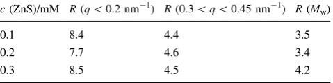
The values obtained for theq-range below 0.2 nm-1and in the range 0.3–0.45 nm-1 (indicated in Fig. 4b by the respective linear fits) are summarized in Table1and show that the typical particle radius is in the range of 4.5 to 8.5 nm, which is in very good agreement with the
observations by TEM and the other techniques, where it should be noted that recently a comparison of methods has shown that SAXS is about the most reliable method to deduce the size of such types of nanoparticles [34]. Further information regarding the particle size is obtained from the extrapolation to the scattering at zero scattering vector, I(0), which is directly related to the particle size by:
Ið0Þ ¼ðSLD ZnSð Þ SLD Hð 2OÞÞ 2
cðZnSÞ MwðZnSÞ qðZnSÞ
4p 3 R
3
ð6Þ where the scattering length densities of ZnS and H2O, and
SLD(ZnS) and SLD(H2O), are 3.30910 11
cm-2 and 9.4791010cm-2 (for a density q(ZnS)=4.09 g/cm3). The radii deduced from the absolute intensity values are similar to the ones derived from the shape of the scattering curves and are in the range of 3.5 to 4.5 nm. These values Fig. 3 Transmission electron
micrograph of colloidal ZnS nanoparticles prepared in aqueous micellar solution of CTAB showing the effect of salt concentration at
[CTAB]=0.5 mM (a) [ZnS]=0.3 mM; (b) [ZnS]=0.5 mM. Inset shows higher magnification image. (c) Powdered ZnS nanoparticles redispersed in water. (d) An agglomerate of 8–10 particles and individual nanoparticle shown in inset (e,f) SEM images of ZnS nanoparticles at different magnifications
Fig. 4 (a) SAXS intensity for samples of different
concentrations of ZnS (h: 0.1 mM,s: 0.2 mM,D: 0.3 mM) prepared in micellar media of CTAB. (b) Guinier plot of the SAXS data of (a) for samples of different
[image:6.595.184.546.57.298.2] [image:6.595.132.545.561.711.2]are somewhat smaller than the ones derived from the slope of the Guinier plots. However, this might be explained by the fact that the distribution contains a rather large amount of small particles and the slope scattering curve being in principle related to a z-average is strongly biased toward the larger sizes. In addition, the particles might be less dense than bulk ZnS, which would also yield larger sizes (while the one deduced from I(0) was assuming bulk density). In summary it can be stated that SAXS confirms the spherical shape of the ZnS nanoparticles and that their typical size is in the range of 3 to 6 nm, where it has to be noticed that the particles are rather polydisperse in both size and distribution as average size are independent of the ZnS concentration employed (Table2).
XRD and FTIR Studies
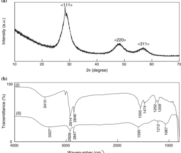
The phase purity, crystallographic structure, and size of nanocrystallites were determined by powder X-ray dif-fraction (XRD). Figure5a represents the powder XRD patterns of ZnS nanoparticles synthesized in CTAB aque-ous micellar system. The product was found to exhibit the characteristic pattern corresponds to face-centered cubic (fcc) structure, and the peaks observed in the XRD patterns match well with those of the cubic ZnS reported in JCPDS powder diffraction file No. 5-0566. No other impurities such as oxides or organic compounds related to reactants were detected by XRD analysis indicating the phase purity of the ZnS product. The three diffraction peaks at 2hvalues of 28.6, 48.1, and 56.8 correspond to\111[,\220[, and
\311[plane, respectively, of cubic ZnS, and the lattice constant, a, was calculated to be 5.427 A°. Broadening of the XRD peaks shows the formation of nanocrystals of ZnS. The crystallite size of ZnS nanoparticles was calcu-lated following the Scherrer’s equation [35]
D¼ ak
bcosh ð7Þ
whereDis the mean particle diameter, a is a geometrical factor (a =0.94), k is the wavelength of X-rays used for analysis, andbis the full width at half maxima (FWHM) of peaks. Herehcorresponding to each plane was selected for
particle size calculation, and the average particle size was found to be 5.8 nm.
The nanoparticle formation takes place due to agglom-eration of the primary particle, which in this case is the single ZnS unit. Agglomeration number specifies the number of primary particles or molecules contained in a single nanoparticle of a given size [36]. Assuming the nanoparticles to be exactly spherical and also evident from TEM, particle agglomeration number was calculated from the following expression [37]
n¼4pNar 3
3Vm
ð8Þ where n is the agglomeration number, Na is Avogadro’s
number,Vmis the molar volume of ZnS in cm3mol-1, and
r is nanoparticle radius. We calculated the agglomeration number to be 2597 for r=2.9 nm. The number of ZnS units contained in a nanoparticles was further confirmed by using another simple method taking into account the lattice parameter, a, calculated above. (The equations for calcu-lating the particle agglomeration number using both the methods are given inAppendix A.)
Adsorption of CTAB on ZnS nanoparticles was exam-ined by recording the FTIR spectra in the range 4,000– 400 cm-1. Figure 5b depicts the FTIR spectra of CTAB and CTAB-capped ZnS nanoparticles. From Fig. 5b, it is to be noted that the symmetric and asymmetric –CH2
stretching vibrations of pure CTAB lie at 2,914 and 2,846 cm-1and remained almost same in the presence of ZnS nanoparticles within the experimental errors. The peaks at 1,550 and 1,474 cm-1for pure CTAB are attrib-uted to –C–H scissoring vibrations of –N–CH3moiety [38],
which are shifted to 1,595 cm-1 in the presence of ZnS nanoparticles. Also the peaks at 1,252 and 1,209 cm-1due to –C–N stretching are suppressed and significantly shifted to 1,212 and 1,067 cm-1 in the presence of ZnS NPs. Therefore, from FTIR results, it is clear that the peaks due to CTAB head group region are shifted without any sig-nificant shift in hydrocarbon tail region. These results confirm the stabilization of ZnS nanoparticles by adsorp-tion of CTA?through head group region as hypothesized on the basis of pH studies (discussed later in this paper). Role of CTAB
Since CTAB is a cationic surfactant, Zn2?ions would not be adsorbed on the micelles. But S2-and HS-ions gen-erated by the ionization of Na2S would interact with
CTA?. Also, the ratio of [Zn(OAc)2]:[Na2S] during the
[image:7.595.51.291.94.154.2]synthesis of ZnS nanoparticles was maintained on 1:2; hence it is suggested that ZnS nanoparticles are capped by CTA? with excess HS- ions adsorbed on the surface of surfactant aggregates.
Table 2 Lower (0.3\q\0.45 nm-1) and upper (q\0.2 nm-1) limit for the particle radiusRand the particle radius as derived from the mean particle volume according to Eq.6
c(ZnS)/mM R(q\0.2 nm-1) R(0.3\q\0.45 nm-1) R(Mw)
0.1 8.4 4.4 3.5
0.2 7.7 4.6 3.4
0.3 8.5 4.5 4.2
To further investigate the process of stabilization, the effect of CTAB concentrations on the ZnS nanoparticles was also investigated at [Zn(OAc)2]=0.5 mM, and
[Na2S]=1 mM with CTAB concentration ranged between
0.5 and 3.5 mM (Fig.6a). It was found that the absorption spectrum of colloidal suspensions of ZnS nanoparticles was not significantly affected by CTAB concentration above 1.0 mM (cmc=0.94 mM) within experimental errors. It can be interpreted from Fig.6a that the blue shift in the absorption shoulder with CTAB concentration is more prominent only up to [CTAB]=1.0 mM; above this concentration, the shoulder remains almost unaffected by CTAB concentration. This indicates the decrease in parti-cle size with increase in surfactant concentration. However, this decrease is more prominent up to [CTAB]=1.0 mM; above this concentration, the size of ZnS nanoparticles is almost independent of surfactant concentration. The only possible reason for such type of behavior seems to be that ZnS nanoparticles are stabilized inside the CTAB micelles. But ZnS nanoparticles have also been synthesized below cmc of CTAB; thus it is suggested that surfactant adsorp-tion on nanoparticles prevents their unlimited growth. At low CTAB concentration, the nanoparticles were larger in size because CTAB monomers were not sufficient to sta-bilize 0.5 mM nanoparticles, whereas 1.0 mM surfactant was sufficient to stabilize 0.5 mM nanoparticles. Thus,
above this concentration, surfactant has almost no effect on the nanoparticle size. This type of behavior of ZnS nano-particles in aqueous CTAB is different from that in SDS [17] where decrease in nanoparticles size with increasing [SDS] was observed.
Effect of pH on Precipitation and Stabilization of ZnS Nanoparticles
To further investigate the precipitation and stabilization processes, the synthesis has also been performed at dif-ferent pH in the range 2–12. The pH was maintained by the addition of acetic acid and NaOH, so that only similar types of ions remain in the solution as were present ini-tially. The absorbance corresponding to shoulder at 294 nm increases with increase in pH reflecting the maximum nanoparticles formation in basic medium (Fig.6b). Thus, the hydrolysis of the Na2S molecules at different pH is
considered to be consisted of the following essential steps. Na2SþH2O!S2þHSþNaþþOH
In acidic medium S2þHþ !HS In basic medium
4000 3000 2000 1000
(b)
100
0
7
6
0
1
2
1
2
1
5
9
5
1
7
4
8
2
0
2
9
2
7
3
3
3
9
0
2
1
2
5
2
1
4
7
4
1
0
5
5
1
6
4
8
2
4
1
9
2
0
1
4
3
_
_
_
_
_
_
_
_
_
_
_
_
_
(II) (I)
)
%(
e
c
n
att
i
m
s
n
ar
T
Wavenumber (cm-1)
10 20 30 40 50 60 70
(a)
2θ (degree)
).
u.
a(
yti
s
n
et
nI <220> <311>
<111>
[image:8.595.180.544.63.369.2]HSþOH!S2þH2O
Thus, in basic medium, more S2- ions are available to combine with Zn2? forming more ZnS nanoparticles, whereas in acidic medium S2-ions are being converted into HS-ions. Also it was noted that particles get agglomerated at low and very high pH due to lack of effective capping by surfactant molecules. The ZnS particles were negatively charged in the pH range of 5.3\pH\9.3, and negatively charged species such as Br-or HS-face an electrostatic barrier to surface adsorption [21]. Thus, it is hypothesized that the ZnS nanoparticles are stabilized by the adsorption of CTA?through ammonium headgroup due to electrostatic interactions, forming surfactant bilayer on the surface of nanoparticles. The counterions (Br-and HS-) are present at the surface of bilayer thus generating excess negative charge again. This type of effective stabilization is not present at low and very high pH and the particles gets agglomerated. Formation of CTAB capped ZnS nanoparti-cles were also confirmed by FTIR studies described earlier.
Nanoparticles Growth in Presence of Surfactant
Figure7a represents UV-visible spectra of ZnS nanodi-spersion in aqueous CTAB as a function of time. In these studies, the particles were produced by rapid mixing of two aqueous micellar solutions, one containing Zn2? and the other containing S2- ions. The solution was then
immediately transferred into quartz cuvette for UV-visible spectroscopy. The mixing time was about 40–45 s before starting the absorbance measurement. The measurements were then carried out at an interval of 3 min. As can be seen, the typical shoulder due to ZnS is progressive red shifted with time and became almost constant after 30 min. The absorbance of the shoulder also follows same trend. This can be interpreted in terms of a growing process of the ZnS nanoparticles and total concentration of absorbing ZnS increases. This is due to the simultaneous nucleation and growth of ZnS nanoparticles. That is, once the nuclei are formed, the collision between one molecule and the nuclei formed leads to growth process, whereas some new nuclei are also being generated by the reaction between Zn2?and S2-ions. Since the nanoparticles formed are polydispersed, it can be hypothesized that ZnS nanoparticles are being stabilized by the adsorption of CTA? during different stages of growth process.
The time-dependent absorption behavior of ZnS nano-particles was also investigated by measuring the UV-absorption at 294 nm as a function of time at different CTAB concentrations with constant Zn(OAc)2=0.5 mM
and Na2S=1.0 mM. The mixing time in these studies was
also 40–45 s. Therefore, time ‘zero’ was on the order of 40–45 s after mixing and the reaction was monitored for 80 min. It can be depicted from Fig. 7b that the absorbance first increases rapidly within the mixing time (40–45 s) and then increases steadily to reach the maximum value. After
240 260 280 300 320 340 0.0
0.5 1.0 1.5 2.0 2.5
)
m
n(
ht
g
n
el
e
v
a
W
(a)
[CTAB]
7 1
)
u.
a(
e
c
n
a
br
o
s
b
A
Wavelength (nm)
0 1 2 3 4
292 293 294 295 296
[ZnS] = 5x10⁻⁴
M
[CTAB] mM
2 4 6 8 10 12 14
0.0 0.1 0.2 0.3 0.4 0.5 0.6 0.7
(b)
[Zns] = 5x10⁻⁴M
[CTAB] = 5x10⁻³M
pH
[image:9.595.177.545.57.338.2]reaching the maximum value, absorbance decreases with a very small plateau region of constant absorbance.
The time taken to reach maximum value and decrease in absorbance depends upon [CTAB]. The decrease in absorbance after reaching a maximum value is attributed to the UV-induced degradation of ZnS. The degradation of ZnS nanoparticles starts at surface and is much faster due to their large surface area [39]. From the investigation of photochemistry of ZnS nanoparticles in the solution in the
presence of oxygen, it is expected that ZnSO4is formed by
the following reaction [40]. ZnSþ2O2!Zn2þþSO42
The absence of the plateau region of constant absorbance in all CTAB concentrations reveals that the process of decay has started before the growth was completed. The effect of UV-radiations on nanoparticles was found to be least at high CTAB concentration, i.e., 5 mM. This type of
240 260 280 300 320 340 0.0
0.4 0.8 1.2 1.6 2.0
t = 30 min
t = 40 sec
).
u.
a(
e
c
n
a
br
o
s
b
A
Wavelength (nm)
).
u.
a(
e
c
n
a
br
o
s
b
A
Wavelength (nm)
292 294 296 298 0.55
0.60 0.65 0.70 0.75 0.80 (a)
0 20 40 60 80
0.68 0.69 0.70 0.71
(b)
Time (min)
[CTAB] 0.5 mM 5.0 mM 2.0 mM
Fig. 7 (a) Absorption spectra of ZnS nanoparticles in 1.5 mM aqueous CTAB as a function of time. [ZnS]=5910-4M. Magnified view of absorption shoulder is shown as insert. (b) UV-absorbance at 294 nm of ZnS nanoparticles
(concentration: 0.5 mM) as a function of time in
spectrophotometer for three different CTAB concentrations
250 300 350 400
0.0 0.4 0.8 1.2 1.6 2.0
Wavelength (nm) [CTAB] = 2mM
[ZnS] = 0.5mM
1
(a)
).
u.
a(
e
c
n
a
br
o
s
b
A
Wavelength (nm)
250 300 350 40 0
0.0 0.4 0.8 1.2 1.6 2.0
4
(b)
No Irradiation 365 nm 254 nm
[image:10.595.182.546.57.313.2] [image:10.595.185.544.451.712.2]behavior might be due to passivation of ZnS surface by surfactant molecules and prevent the direct impact of UV-light.
The UV-induced corrosion of nanoparticles was further confirmed by irradiating the samples in UV-irradiation cabinet for different time durations and the results are shown in Fig.8a. In addition, the effect of different UV-wavelength on spectroscopic properties of ZnS nanoparticles was also investigated and the absorption spectra are depicted in Fig.8b. The results show that short wavelength (high energy) radiations etch the nanoparticle to a larger extent than that by longer wavelength (low energy) radiations.
Summary
The ZnS nanoparticles have been prepared in aqueous micellar solution of CTAB. On the basis of various studies reported in the paper, the nanoparticles are found to effectively cap adsorption of CTA? through head group. The adsorption process is pH dependent, as the particles are more stable over a particular pH range. TEM and SEM images show the spherical morphology of the nanoparti-cles, but due to agglomeration there may be some change in shape, which is confirmed by SAXS experiments in the liquid state. The dried samples have also been character-ized using TEM, absorbance, and fluorescence emission and compared with those in aqueous micellar solution. The results reveal that although particles show agglomeration in powdered form, they show good tendency for redispersion in water. Fluorescence studies reveal some crystal defects in the nanoparticles during separation drying process. The time-dependent adsorption behavior reveals that stabiliza-tion of nanoparticles by CTAB follows different mechanisms at different CTAB concentrations. The exact mechanism is still not very clear and further studies are to be carried out in this context. All these findings seem to be very useful to define the stability of ZnS nanoparticles during synthesis in aqueous micellar media.
Acknowledgments Sanjay Kumar is thankful to CSIR, India, for fellowship. S. K. Mehta and Michael Gradzielski are grateful to DST and DAAD for the award of Project Based Personal Exchange Pro-gramme (PPP)-2008. We would like to thank T. Narayanan and P. Panine from ESRF and P. Heunemann from TU Berlin for help with the SAXS measurements.
Appendix A
Calculation of Agglomeration Number
Method 1 The agglomeration number can be calculated by using the following equation [38]
n¼4pNar 3
3Vm
ðiÞ
where Na is Avogadro’s number, r is the radius of the
nanoparticle, and Vm is the molar volume of ZnS. The
molar volume (Vm) is defined as
Vm¼
MZnS
q ðiiÞ
whereMZnSis the molar mass andqis the density of ZnS.
Substituting the values ofp,Na,MZnS, andq =4.023 g/cm3,
Eq. 1reduces to
n¼105:8r3 ðiiiÞ
whereris the radius in nanometers.
Method 2 Considering the nanoparticle to be spherical, the volume of single nanoparticle with radius ‘r’ is given by
V ¼4pr 3
3 ðivÞ
The volume of the cubic unit cell with lattice parameter ‘a’ is given by
V0¼a3 ðvÞ
Therefore, number of unit cells per nanoparticle= V V0 ¼ x (say) Since, nanocrystals were found to have FCC arrangement, there must be four ZnS units per unit cell. Thus, agglomeration number
n¼4x
References
1. L.E. Brus, J. Chem. Phys.80, 4403 (1984). doi:10.1063/1.447218
2. A. Hasselbarth, A. Eychmuller, H. Weller, Chem. Phys. Lett.133, 203 (1986)
3. Y. Wang, Acc. Chem. Res. 24, 133 (1991). doi:10.1021/ ar00005a002
4. S. Kar, S. Chaudhri, J. Phys. Chem. B109, 3298 (2005). doi:
10.1021/jp045817j
5. X.D. Gao, X.M. Li, W.D. Yu, Thin Solid Films468, 43 (2004). doi:10.1016/j.tsf.2004.04.005
6. R. Chen, D.J. Lockwood, J. Electrochem. Soc.149, S69 (2002). doi:10.1149/1.1502258
7. S.C. Ghosh, C. Thanachayanont, J. Dutta,ECTI-CON(Pattaya, Thailand, 2004), p. 145
8. B.G. Wang, E.W. Shi, W.Z. Zhong, Cryst. Res. Technol.35, 279 (2000). doi:10.1002/1521-4079(200003)35:3\279::AID-CRAT 279[3.0.CO;2-Q
9. R. Lv, C. Cao, Y. Guo, H. Zhu, J. Mater. Sci.39, 1575 (2004). doi:10.1023/B:JMSC.0000016154.71163.b8
11. N.I. Kortyokhova, E.U. Buzaneva, C.C. Waraksa, N.R. Martin, T.E. Mallouk, Chem. Mater. 12, 383 (2000). doi:10.1021/ cm990395p
12. C. Falcony, M. Garcia, A. Qrtiz, J.C. Alonso, J. Appl. Phys.72, 1525 (1992). doi:10.1063/1.351720
13. R. Maity, K.K. Chattopadhyay, Nanotech15, 812 (2004). doi:
10.1088/0957-4484/15/7/017
14. Y. Yang, J. Huang, S. Liu, J. Shen, J. Mater. Chem. 7, 131 (1997). doi:10.1039/a603555h
15. H.C. Warad, S.C. Ghosh, B. Hemtanon, C. Thano, C.J. Dutta, Sci. Technol. Adv. Mater.6, 296 (2005)
16. Q. Wu, N. Zheng, Y. Ding, Y. Li, Inorg. Chem. Commun.5, 671 (2002). doi:10.1016/S1387-7003(02)00523-3
17. D. Mitra, I. Chakraborty, S.P. Moulik, Colloid J.67, 494 (2005). doi:10.1007/s10595-005-0117-1
18. S.-D. Han, K.C. Singh, H.-S. Lee, T.-Y. Cho, J.P. Hulme, C.-H. Han, I.-S. Chun, J. Gwak, Mater. Chem. Phys. (2008) (in press) 19. A. Murugadoss, A. Chattopadhyay, Bull. Mater. Sci. 31, 533
(2008). doi:10.1007/s12034-008-0083-4
20. S. Paria, K.C. Khilar, Adv. Colloid Interface Sci.110, 75 (2004). doi:10.1016/j.cis.2004.03.001
21. X.V. Zhang, S.P. Ellery, C.M. Friend, H.D. Holland, F.M. Michel, M.A.A. Schoonen, S.T. Martin, J. Photochem. Photobiol. Chem.168, 153 (2004). doi:10.1016/j.jphotochem.2004.03.028
22. M.K. Naskar, A. Patra, M. Chattrerjee, J. Colloid. Interface. Sci.
297, 271 (2006). doi:10.1016/j.jcis.2005.10.057
23. N.M. Huang, C.S. Kan, P.S. Khiew, S. Radiman, J. Mater. Sci.
39, 2411 (2004). doi:10.1023/B:JMSC.0000020003.51378.55
24. O. Schmelz, A. Mews, T. Basche, A. Herrmann, K. Mullen, Langmuir17, 2861 (2001). doi:10.1021/la0016367
25. J. Tauc, A. Menth, Non-Cryst. Solids569, 8 (1972)
26. Y. Wang, A. Suna, W. Mahler, R. Kasowaki, J. Chem. Phys.87, 7315 (1987). doi:10.1063/1.453325
27. Y. Wang, N. Herron, J. Phys. Chem.95, 525 (1991). doi:10.1021/ j100155a009
28. J.H. Yu, J. Joo, H.M. Park, S. Bark, Y.W. Kim, S.C. Kim, T. Hyeon, J. Am. Chem. Soc. 127, 5662 (2005). doi:10.1021/ ja044593f
29. J.F. Suyver, S.F. Wuister, J.J. Kelly, A. Meijerink, Nano. Lett.1, 429 (2001). doi:10.1021/nl015551h
30. C. Burda, M.A. El-sayed, Pure Appl. Chem.72, 165 (2000). doi:
10.1351/pac200072010165
31. R. Maity, K.K. Chattopadhyay, Nanotechnology15, 812 (2004). doi:10.1088/0957-4484/15/7/017
32. I. Chakraborty, S.P. Moulik, J. Nanopart. Res.7, 237 (2005). doi:
10.1007/s11051-005-3472-2
33. A. Guinier, G. Fournet,Small-Angle Scattering of X-rays(Wiley, New York, 1955)
34. A.K. Keshari, A.C. Pandey, J. Nanosci. Nanotechnol. 8, 1221 (2008). doi:10.1166/jnn.2008.370
35. L.P. Wang, G.Y. Hong, Mater. Res. Bull.35, 695 (2000). doi:
10.1016/S0025-5408(00)00261-0
36. J.M. Nedeljkovic, R.C. Patel, P. Kaufman, C.J. Pruden, N. O’Leary, J. Chem. Educ.70, 342 (1993)
37. P.A. Sant, P.V. Kamat, Phys. Chem. Chem. Phys.4, 198 (2002). doi:10.1039/b107544f
38. Z. Sui, X. Chen, L. Wang, Y. Chai, C. Yang, J. Zhao, Chem. Lett.
34, 100 (2005). doi:10.1246/cl.2005.100
39. A. Henglein, M. Gutierrez, Ber. Bunsenges. Phys. Chem.87, 852 (1983)

![Fig. 6 (spectra of ZnS nanoparticles atdifferent CTAB concentrations.[CTAB]: (1) 0.5 mM, (2)1 mM, (3) 1.5 mM, (4) 2 mM,(5) 2.5 mM, (6) 3 mM, (7)3.5 mM](https://thumb-us.123doks.com/thumbv2/123dok_us/8843983.932117/9.595.177.545.57.338/fig-spectra-zns-nanoparticles-atdifferent-ctab-concentrations-ctab.webp)
![Fig. 7 (of ZnS nanoparticles in 1.5 mMaqueous CTAB as a function oftime. [ZnS]a) Absorption spectra = 5 9 10-4 M.Magnified view of absorptionshoulder is shown as insert](https://thumb-us.123doks.com/thumbv2/123dok_us/8843983.932117/10.595.185.544.451.712/nanoparticles-mmaqueous-function-oftime-absorption-spectra-magnied-absorptionshoulder.webp)
