N A N O E X P R E S S
High-yield Synthesis of Multiwalled Carbon Nanotube
by Mechanothermal Method
S. A. ManafiÆM. H. AminÆM. R. Rahimipour Æ E. SalahiÆA. Kazemzadeh
Received: 11 July 2008 / Accepted: 30 December 2008 / Published online: 22 January 2009 to the authors 2009
Abstract This study reports on the mechanothermal synthesis of multiwalled carbon nanotube (MWCNTs) from elemental graphite powder. Initially, high ultra-active graphite powder can be obtained by mechanical milling under argon atmosphere. Finally, the mechanical activation product is heat-treated at 1350C for 2–4 h under argon gas flow. After heat-treatment, active graphite powders were successfully changed into MWCNTs with high purity. The XRD analyses showed that in the duration 150 h of milling, all the raw materials were changed to the desired materials. From the broadening of the diffraction lines in the XRD patterns, it was concluded that the graphite crystallites were nanosized, and raising the milling duration resulted in the fineness of the particles and the increase of the strain. The structure and morphology of MWCNTs were investi-gated using scanning electron microscopy (SEM) and high-resolution transmission electron microscopy (HRTEM). The yield of MWCNTs was estimated through SEM and TEM observations of the as-prepared samples was to be about 90%. Indeed, mechanothermal method is of interest for fundamental understanding and improvement of com-mercial synthesis of carbon nanotubes (CNTs). As a matter of fact, the method of mechanothermal guarantees the production of MWCNTs suitable for different applications.
Keywords Carbon nanotubesMechanothermal NanotechnologyAdvanced materials
Outstanding structure
Introduction
Since the time of discovery by Iijima [1], there has been much interest in the synthesis and physical properties of carbon nanotubes (CNTs) due to their important applica-tions. For example, CNTs can be used as electrochemical devices [2], for hydrogen storage [3], field emission devi-ces [4], and nanotweezers [5]. Various methods have been developed for the synthesis of carbon nanotubes, including metalcatalyzed chemical vapor deposition (CVD) [6–8], arc evaporation [9], laser ablation of carbon [10], catalytic decomposition [11], HiPCO process [12] or pulsed laser vaporization (PLV) [13]. There are growing experimental evidences, showing that the formation of both multiwalled and single-walled nanotubes involves a solid-phase trans-formation in the gas-phase synthesis processes [14–16]. It implies that a direct synthesis of CNTs by a transformation of solid carbons under mild conditions is possible; if accessible, then it would be quite beneficial for a large-scale synthesis due to the intrinsic high-feeding- density characteristic of the solid-phase reaction process.
Recently, successful syntheses of CNTs by the solid-phase transformation of granular carbon materials, such as carbon black, amorphous carbon, and fullerene soot, achieved at extremely high temperatures (2000–3000C) have been reported [15–23]. However, further technical improvement for practical access and clear understanding of the transformation mechanism for rational process design and control are still necessary and challenging tasks. Zhenping Zhu et al. recently synthesized MWCNTs by the solid-phase transformation of metal-containing glass-like carbon nanoparticles by heating at temperatures of 800– 1000C [24]. More recently, we have suggested that using washable supported catalysts is accompanied by valuable advantages and with an extraordinary structure [25,26]. S. A. Manafi (&)M. H. AminM. R. RahimipourE. Salahi
A. Kazemzadeh
Ceramic Department, Materials and Energy Research Center, P.O. Box 14155-4777, Tehran, Iran
Herein, we study mechanothermal method for synthe-sizing MWCNTs that consists of mechanical milling (for obtaining amorphous carbon nanostructure using ultra-high purity graphite powders) and thermal annealing processes (for transforming into nanotubes via carbon nanostructure and structural crystallization). The latest finding of this article demonstrates that this simple technique is a prom-ising tool to synthesize the MWCNTs with ultra-high purity and high yield without a need for specialized equipment and or a multi-step purification process to eliminate the amorphous carbon and MWCNTs.
Experimental Details
Elemental graphite flakes (99.9%\100lm) with a purity of 99.8% were mechanically ground in a purified argon atmo-sphere. Four grams of 10 steel balls of diameter 15 mm were used in the mechanical activation (MA) process. The ball-to-powder weight ratio was kept at 20:1. The MA was carried out at ambient temperature and at a rotational speed (cup speed) of 700 rpm in a planetary ball mill. The MA process was inter-rupted at regular intervals with a small amount of the mechanically activated powder being taken out of the vial to study changes in the microstructures at selected milling duration. The vial containing the powders and the balls were evacuated by a rotary pump and then back-filled with pure argon gas (99.99%) in a glove box. The final gas pressure in the vial was kept at 0.1 MPa. After full amorphization, the highly chemically active carbon powders were annealed at different temperatures to investigate the formation of MWCNTs. The crystal phase was determined with powder X-ray diffraction. For these experiments, a Siemens diffractometer (30 kV and 25 mA) with the Ka1, radiation of copper (k=1.5406 A˚´ ), was used. The structural and compositional information of the product materials was obtained with scanning election microscopy (SEM) and energy-dispersive X-ray spectroscopy (SEM/EDX, XL30), field emission transmission electron microscopy, and selected area electron diffraction (FETEM/ SAED, Philips CM200 transmission electron microscope operated at 200 kV). Specific surface areas (SSAs) of carbon/ CNTs were also measured by the Brunauer–Emmett–Teller (BET) method. The BET surface areas,SBET, of the samples were determined from N2adsorption–desorption isotherms obtained at 77 K using an ASAP 2010 surface area analyzer. The BET method is the most widely used procedure for the determination of the surface areas of solid materials and involves the use of the BET equation:
1
W½ðP0=PÞ 1 ¼ 1
WmC
þC1
WmC P P0
wherein W is the weight of gas adsorbed at a relative pressure of P/P0 and Wm is the weight of adsorbate
constituting one monolayer of surface coverage. The term
C, the BET C constant, is related to the energy of adsorption in the first adsorbed layer, and consequently, its value is an indication of the magnitude of the adsorbent– adsorbate interactions. When the range of P/P0 is 0.05– 0.35, a line will be obtained. Through the slope and intercept, the adsorbate monolayer saturation amount (Vm) can be obtained. The BET surface area equation is:
SBET¼VmN0r=22400W
where N0 is Avogadro’s number and r is the cross-sectional area of a single molecule. Raman spectra at room temperature under ambient condition using an Almega Raman spectrometer with an Ar? at an excitation wavelength of 514.5 nm were obtained. The crystalline size, D, was estimated by the equation from Williamson-Hall [27]:
bcosh¼2esinhþ0:9k
D
wherekis the wavelength of the X-ray,bthe full width at half-maximum (FWHM), h the Bragg angle, ande is the microstrain.
Results and Discussion
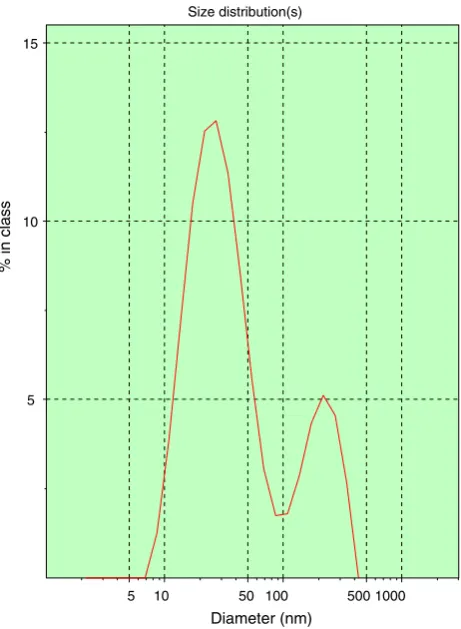
As previously discussed, the size of the carbon particles is one of the important factors for the formation of the CNTs [28]. It is predicted that nanosized carbon particles could catalyze the growth of CNTs. The nanoparticle size of carbon-milled product was analyzed using a zeta-sizer method. These measurements reveal the particles to be of highly wide distribution (Fig.1). The milled graphite powders were particles with diameters in two ranges, i.e., from 7–100 nm and 100–400 nm.
The XRD patterns of graphite powder mechanically mixed in argon atmosphere for several activation periods are shown in Fig.2, where the patterns at an activating time of 0 h (before MA) were reduced to one-fifth because of the strong diffraction intensity of the elemental powder. The constitution of this starting powder corresponds to the elemental graphite powder. The diffraction intensities drastically decreased after MA. The diffraction peaks corresponding to the graphite (particularly, the peak at about 2h=26.6) almost disappeared at an activating time of 10 h. The crystalline size of the graphite after MA for 5 h is approximately D=30.1 nm whereas that before MA is approximately D=31.1 (Table1) so that about
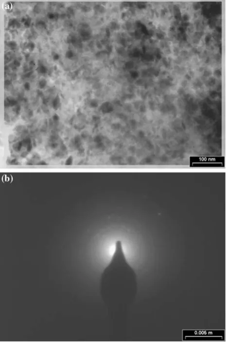
peaks at around 2h=26.6can not be eliminated after an activating time of 100 h, suggesting that the formation of an amorphous-like phase or very fine particles has been strongly enhanced in the argon atmosphere after an acti-vating time of 150 h. Figure3 shows the transmission electron micrograph (Fig.3a) and SAED (Fig.3b) patterns of graphite nanostructures synthesized according to the method described above. It is readily observed that the nanostructures are in a high ultra-fine dispersion and
the average crystalline size is 10 nm. Meanwhile, the electron diffraction pattern reveals that the carbon nano-structures have an amorphous structure (Fig.3b). At the same time, this result is consistent with the X-ray diffrac-tion (XRD) pattern. We believe that the very small size and the amorphous structure are due to the high-energy ball milling of the graphite powders activated by planetary mill. Also, Jiang and Chen [28] recently developed a thermo-dynamic quantitative model to describe the phase transitions of nanocarbon as functions of its size and temperature through systematically considering the effects of surface stresses and surface energies. The fine nanosize amorphous structure of pure carbon nanostructures is thermodynamically unstable, owing to the high amount of free energy. Therefore, crystallization at a temperature regime might be expected.
The milled powders had an average crystalline size of about 5–10 nm as determined by the Williamson-Hall Size distribution(s)
5 10 50 100 500 1000
Diameter (nm)
5 10 15
% in class
Fig. 1 The nanoparticle size of milled carbon measured by zeta-sizer
0 500 1000 1500 2000 2500 3000
0 20 40 60 80
2 Theta
Intensity
150 h MA 50 h MA 10 h MA 0 h MA
Fig. 2 The X-ray diffraction spectra of mechanically alloyed
[image:3.595.56.287.57.372.2]graph-ite powders at different milling times
Table 1 Characteristics of different samples used for investigation
during milling
Milling time (h)
Sample (Id)
SA (m2/ g)
Crystalline size=D (nm)
0 C0 5.5 31.1
5 C5 21.2 30.1
10 C10 25.8 29.8
20 C20 31.5 29.1
30 C30 35.1 27.4
40 C40 39.9 26.2
50 C50 45.6 25.4
60 C60 50.1 24.6
70 C70 56.1 23.9
80 C80 62.5 22.1
90 C90 70.2 20.1
100 C100 78.9 18.5
110 C110 91.1 17.1
120 C120 115.2 13.9
130 C130 145.2 11.2
140 C140 175.5 8.5
150 C150 200.5 5.2
160 C160 205.5 4.9
170 C170 207.4 4.8
180 C180 209.1 4.7
190 C190 209.5 4.8
200 C200 211.2 4.8
210 C210 211.2 4.8
220 C220 211.2 4.8
[image:3.595.305.545.80.433.2] [image:3.595.55.290.538.685.2]method as shown in Table1. Crystalline size values determined in this way may be low when the concentration of defects in the sample is higher compared to that in the reference large-particulate powder. The BET areas are vastly different for all the samples ranging between 5.5 and 211.2 m2/g as presented in Table1. In the steady state, the BET surface area of the mechanically activated powders was determined to be about 211.2 m2/g for several samples (C200, C210, C220 and …). Measuring the surface area of carbon nanostructures via nitrogen adsorption by the Bru-nauer–Emmet–Teller (BET) method revealed a specific surface area of 211.2 m2/g which seems relevant for sur-face area-dependent applications such as diffusion process. Assuming that all the particles are spherical and have the same theoretical density, and form:dBET=6/Sq, where Sis the surface area andqis the particle density (2.1 g/cm3 for graphite), a BET particle diameter, dBET, of about 20 nm is found for these nanoparticles. These results are also consistent with the HRTEM image observations. Therefore, the obtained results of specific area (SA) and
crystalline size (D) for milled graphite indicate that graphite particles are highly chemically active.
The HRTEM micrographs of the powders mechanically milled for 150 h in argon gas atmosphere as shown in Fig.4, show that mechanically activated powders are an ultra-fine spherical particle powder with approximately 100 ±20 nm in size. Because of being highly chemically active carbon atoms, these are strongly agglomerated. On the other hand, the amorphous structure of pure graphite nanoparticles is thermodynamically unstable, owing to the high amount of free energy.
Figure5a–d shows extraordinary morphologies of the as-prepared MWCNTs. Interestingly, the carbon crystal-lites self-organized to form tubular assemblies or ‘‘spaghetti’’ with a peculiar appearance. Under the reported conditions, the CNT products are all in this morphology (100%), with diameters ranging from 20±10 nm and lengths of several millimeters. The SEM analyses have shown that a majority (i.e., about 90%) of the synthesized powder at 1350C correspond to spring-like MWCNTs (Fig.5c–d).
Figure6 shows the transmission electron micrograph and electron diffraction of the nanostructures milled as described above. The HRTEM was employed to further characterize the structure of synthesized powder through mechanothermal method. TEM examinations of this sam-ple indicate that they are nanotubes, in which the graphic layers are not clear and have small hollow cores. To pre-pare transmission electron microscope samples, the nanotubes were transferred to a carbon-coated copper gird. A drop of alcohol was first added to the nanofiber film. Then, the film was scratched by a pair of tweezers attached to the carbon-coated copper gird. Most of the nanotubes are
Fig. 4 Mechanically activated graphite powders treated for 150 h in
[image:4.595.54.288.64.418.2]argon gas atmosphere
Fig. 3 a High resolution transmission electron microscope
[image:4.595.308.542.506.683.2]bent and have a uniform diameter along its entire length, indicating the growth anisotropy in the one-dimensional is strictly maintained throughout the process. Finally, the HRTEM microscope image shows that individual graphitic carbon is a CNT with a highly uniform structure (Fig.6a). The TEM analyses have shown that a majority (i.e., about 90%) of the synthesized powder at 1350C correspond to spaghetti-like carbon nanofibers (Fig.6a).
Figure6b shows HRTEM images of individual MWCNTs (C150). The average diameter of resulting MWCNTs with a length of about several millimeters is in the range of 30– 70 nm at the open and closed end. Also, we found that the carbon nanotube has a spring-like shape. The SAED pattern (not shown) exhibits a pair of small but strong arcs for (002), together with a ring for (100), and a pair of weak arcs for (004) diffractions. The appearance of (002) diffractions as a pair of arcs indicates some orientation of the (002) planes occurring in the carbon tubes [29].
The Raman spectrum is shown in Fig.7, displaying the characteristically wide D- and G-bands at around 1360 and 1590 cm-1, respectively, typical of amorphous carbons or disordered graphite [30–32]. The peak at 1581 cm-1 (G-band) corresponds to a E2g mode of graphite and is related to the vibration of sp2-bonded carbon atoms in a two-dimensional hexagonal lattice, such as that found in a graphite layer [33]. Nanotubes with concentric multiwalled layers of hexagonal carbon lattice display the same vibra-tion [34]. The D-band at around 1360 cm-1is associated
with vibrations of carbon atoms with dangling bonds in plane terminations of disordered graphite or glassy car-bons. After treatment, the D-band nearly disappeared and the G-band became more sharpened, and so the relative intensity of the G-band with respect to the D-band increased very significantly. The inverse of the ID/IG intensity ratio between G and D bands is an usual mea-surement of the graphitic ordering and may also indicate the approximate layer size in the hexagonal plane, La, [35] which in this case is related to the length of pristine (defect-free) graphitic multiwalls. The ID/IG ratio in the treated material is*0.03, compared to a value of*0.9 in the pre-treated material. The calculation using the rela-tionship La 44(ID/IG)-1yields values of around 1.5lm for the treated sample, which are in good agreement with the maximum lengths of MWCNTs observed in TEM images. The sharp decrease in the value of ID/IGindicates that the number of sp2-bonded carbon atoms without dangling bonds has increased at the expense of disordered carbon. The low ratio ofID/IGis characteristic of a graphite lattice with perfect two-dimensional order in the basal plane. The spectrum in Fig.7 indicates a nearly defect-free lattice ordering, and reveals that the multiwalls forming the nanotubes have a perfect lattice without defects, edges, or plane terminations, as seen in Fig.7. The crystallinity of mechanothermal MWCNTs is similar to or higher than in multiwall nanotubes developed using evaporation methods, for whichID/IGratios are typically*0.10.
Fig. 5 SEM different images of
mechanically activated graphite powders for 150 h after annealing at different temperatures:
[image:5.595.184.546.57.330.2]Conclusions
In summary, we have postulated a simple method for producing high-yield MWCNTs under mechanothermal conditions. Elemental graphite powder was milled in a planetary ball mill at atmospheric pressure and room
temperature. Finally, after annealing at 1350C, we obtained high-yield MWCNTs. This method also presents a facile route to high-yield MWCNTs without complex purification processes. The yield and good quality of MWCNTs obtained by mechanothermal makes it a suitable promising method of synthesis for the production of MWCNTs or other graphitic nanocarbons. Indeed, because of the simplicity and high yield of this route, it may potentially be applied on the scale of industrial production.
Acknowledgments The authors thank the Tarbit Modarres
Uni-versity for access to Raman spectroscopy and their technical support. In addition, the authors would like to acknowledge Dr. Hesari for investigating TEM image, Professor Torabi for helping in the prep-aration of this article, and Mr Jabbari for performing the experimental tests.
References
1. S. Iijima, Nature354, 56 (1991). doi:10.1038/354056a0 2. R.H. Baughman, C.X. Cui, A.A. Zakhidov, Z. Iqbal, J.N. Barisci,
G.M. Spinks, G.G. Wallace et al., Science284, 1340 (1999). doi: 10.1126/science.284.5418.1340
3. C. Liu, Y.Y. Fan, M. Liu, H.T. Cong, H.M. Cheng, M.S. Dres-selhaus, Science286, 1127 (1999). doi:10.1126/science.286.544 2.1127
4. M. Shim, A. Javey, N.W.S. Kam, H.J. Dai, J. Am. Chem. Soc. 123, 11512 (2001). doi:10.1021/ja0169670
5. P. Kim, C.M. Lieber, Science 286, 2148 (1999). doi:10.1126/ science.286.5447.2148
6. A. Peigney, P. Coquay, E. Flahaut, R.E. Vandenberghe, E. De Grave, C. Laurent, J. Phys. Chem. B 105, 9699 (2001). doi: 10.1021/jp004586n
7. S.R. Jian, Y.T. Chen, C.F. Wang, H.C. Wen, W.M. Chiu, C.S. Yang, Nanoscale Res. Lett.3, 230 (2008). doi:10.1007/s11671-008-9141-5
8. M.M. Shaijumon, A. Leela Mohana Reddy, S. Ramaprabhu, Nanoscale Res. Lett. 2, 75 (2007). doi:10.1007/s11671-006-9033-5
9. D.S. Bethune, C.H. Kiang, M.S. de Vries, G. Gorman, R. Savoy, J. Vazquez, R. Beyers, Nature363, 605 (1993). doi:10.1038/363 605a0
10. C.D. Scott, S. Arepalli, P. Nikolaev, R.E. Smalley, Appl. Phys. A 72, 573 (2001). doi:10.1007/s003390100761
11. M. Joseyacaman, M. Mikyoshida, L. Rendon, J.G. Santiesteban, Appl. Phys. Lett.62, 657 (1993). doi:10.1063/1.108857 12. P. Nikolaev, M.J. Bronikowski, R.K. Bradley, F. Rohmund, D.T.
Colbert, K.A. Smith, R.E. Smalley, Chem. Phys. Lett.313, 91 (1999). doi:10.1016/S0009-2614(99)01029-5
13. J. Liu, A.G. Rinzler, H. Dai, J.H. Hafner, R.K. Bradley, P.G. Boul, A.H. Lu et al., Science280, 1253 (1998). doi:10.1126/science. 280.5367.1253
14. G.X. Du, S.A. Feng, J.H. Zhao, C. Song, S.L. Bai, Z.P. Zhu, J. Am. Chem. Soc.128, 15405 (2006). doi:10.1021/ja064151z 15. P.J.F. Harris, S.C. Tsang, J.B. Claridge, M.L.H. Green, J. Chem.
Soc.90, 2799 (1994)
16. P.J.F. Harris, Carbon45, 229 (2007). doi:10.1016/j.carbon.2006. 09.023
17. J.M.C. Moreno, M. Yoshimura, J. Am. Chem. Soc. 123, 741 (2001). doi:10.1021/ja003008h
18. S. Seelan, D.W. Hwang, L.P. Hwang, A.K. Sinha, Vacuum75, 105 (2004). doi:10.1016/j.vacuum.2004.01.073
0 100 200 300 400 500 600 700 800 900 1000
0 300 600 900 1200 1500 1800 2100 2400
Raman shift (cm-1)
Intensity
Fig. 7 Raman spectra of the obtained MWCNTs
Fig. 6 TEM images of mechanically activated graphite powders for
[image:6.595.52.286.59.409.2] [image:6.595.54.286.459.610.2]19. J.Q. Hu, Y. Bando, F.F. Xu, Y.B. Li, J.H. Zhan, J.Y. Xu et al., Adv. Mater.16, 153 (2004). doi:10.1002/adma.200306193 20. J.Q. Hu, Y. Bando, J.H. Zhan, C.Y. Zhi, F.F. Xu, D. Golberg,
Adv. Mater.18, 197 (2006). doi:10.1002/adma.200501571 21. D. Ugarte, Carbon32, 1245 (1994). doi:10.1016/0008-6223(94)90
108-2
22. W.K. Hsu, J.P. Hare, M. Terrones, H.W. Kroto, D.R.M. Walton, P.J.F. Harris, Nature377, 687 (1995). doi:10.1038/377687a0 23. S.P. Doherty, D.B. Buchholz, B.J. Li, R.P.H. Chang, J. Mater.
Res.18, 941 (2003). doi:10.1557/JMR.2003.0129
24. G. Du, C. Song, J. Zhao, S. Feng, Z. Zhu, Carbon46, 92 (2008). doi:10.1016/j.carbon.2007.10.029
25. S.A. Manafi, H. Nadali, H.R. Irani, Mater. Lett.62, 4175 (2008). doi:10.1016/j.matlet.2008.05.072
26. A. Eftekhari, S.A. Manafi, F. Moztarzadeh, Chem. Lett.35, 138 (2006). doi:10.1246/cl.2006.138
27. G.K. Williamson, W.H. Hall, Acta Metall. 1, 22 (1953). doi: 10.1016/0001-6160(53)90006-6
28. Q. Jiang, Z.P. Chen, Carbon44, 79 (2006). doi:10.1016/j.carbon. 2005.07.014
29. T. Kyotani, L.F. Tsai, A. Tomita, Chem. Mater.8, 2109 (1996). doi:10.1021/cm960063?
30. C.A. Dyke, J.M. Tour, Chem. Eur. J. 10, 812 (2004). doi: 10.1002/chem.200305534
31. A. Jorio, A.G. Souza Filho, G. Dresselhaus, M.S. Dresselhaus, A.K. Swan, M.S. Unlu, B.B. Goldberg et al., Phys. Rev. B65, 155412 (2002). doi:10.1103/PhysRevB.65.155412
32. A. Jorio, R. Saito, J.H. Hafner, C.M. Lieber, M. Hunter, T. McClure, G. Dresselhaus, M.S. Dresselhaus, Phys. Rev. Lett.86, 1118 (2001). doi:10.1103/PhysRevLett.86.1118
33. M. Lamy de la Chapell, S. Lefrant, C. Journet, W. Maser, P. Ber-nier, Carbon36, 705 (1998). doi:10.1016/S0008-6223(98)00026-8 34. A. Kasuya, Y. Sasaki, Phys. Rev. Lett. 78, 44347 (1997). doi:
10.1103/PhysRevLett.78.4434