http://dx.doi.org
A M
Squeez
ABSTRAC
In this study w effects presen tioned devices fectly vacuum strate, which electro-statica To accurately eling squeeze plate elasticity solve the coup coupled with problem at ha ments of whic evaluated for trostatic press single step, us and published
Keywords: Sq
1. Introduc
The wide sca MEMS senso to increasing due to the thin cally such de brating norma trapped in-bet sions of the height of the spring and a squeeze film nant dissipatio operating in
*Corresponding a
g/10.4236/jamp.
Monolith
ze Film
Anish 1Depart 2CenterCT
we describe an nt in vibratory s often consist m packed. This behaves like a ally, necessitati model these d film effects fo y often use ap pled fluid elast the 3D elastic and, using only ch the lowest la these nodes on ure load on the sing only one e d experimental
queeze Film D
ction
ale application rs, using para
interest in the n film of air tr evices consist ally to a fixed tween (see Fig
plate happen air gap, the tra viscous damp effect. Squeez on mechanism the aforemen author. .2013.16005
hic, FEM
Proble
Using
h Roychowdh tment of Mecha for Nano Sciencn FEM-based m MEMS devic t of a plate-lik s results in a th
a squeeze film ing the thin air devices the squ or rigid motion pproximate mo ticity problem city Equation. y one type of e
ayer of nodes nly. We also a e top surface o element type.
data.
Damping; Coup
n of electro-s allel plate capa
e study of ene rapped in such of a plate lik substrate, with
gure 1).If the to be much apped air beha per, a phenom
ze film dampin m in Si based
ntioned condi
M-Base
m of an
g 3D 27
hury1,2*, Aru anical Engineerin
ce and Engineer Email: *anishro Receiv
methodology t ces, such as re ke structure tha hin film of air m offering both r gap for impro ueeze film effe n for both perfo ode shapes as m, report iterativ
. In this work element (27 no is also treated apply an electr of the structure The FEM resu
pled Problem;
statically drive acitors have le ergy dissipatio h devices. Typ ke structure, v h a thin air film e lateral dimen
larger than th aves both like menon known a ng is the dom MEMS device itions [1]. Th
ed Appr
n Oscill
7-Node
p Nandy1, C ng, Indian Instit ring, Indian Insti [email protected] ved August 2013
to solve the co esonators, gyro at vibrates nor
being sandwic h stiffness and
oving the effic ect must be inc forated as well input to the 2D ve FEM-based
we present a ode 3D brick). as the fluid do rostatic loadin e. Thus we solv ults show good
27-Node Brick en ed on pi- vi- m n-he a as mi- es he squeeze dynami [2]. In sary to due to tems in structur main e Figure brating
roach fo
ating E
Elemen
C. S. Jog1, Ru tute of Science, itute of Science, sc.ernet.in 3
oupled fluid-str oscopes, and a rmal to a fixed ched between d damping. Ty ciency of actua corporated. Ex as non-perfor D Reynolds E d solution strat a FEM-based s . The structure omain (2D) an
g to our mode ve the coupled d agreement w
k; Micro-Plate
e film offered ic characterist order to correc accurately de the squeeze fi nvolves coupli ral and fluid. ffect is model
1. Schematic o elastic plate an
for the C
Elastic M
nts
udra Pratap1 Bangalore, Indi , Bangalore, Ind
ructure proble acoustic transd d substrate, an
the moving pl ypically, such s ation and the s xtensive literatu
ated plates. Stu Equation. Rece
tegies for the 2 single step sol e is modeled w nd the integrals el by consideri d 2D-fluid-3D-with both existin
e
d damping and tics of the vib ctly model suc etermine the s ilm. Accurate ing of three d Traditionally led using the l
of an air film nd a fixed subst
Coupled
Micro-P
1,2 a dia
em due to sque ducers. The af d is generally late and the fix structures are
ensitivity of d ure is present udies which m ent works whic 2D Reynolds E lution for the with 27 node b
s over fluid dom ing an equival -structure prob ng analytical s
d stiffness chan bratory MEMS ch devices, it i stiffness and d
modeling of s domains, electr the squeeze lubrication the trapped betwe trate.
d
Plate
eeze film foremen- not per- xed sub- actuated detection. on mod- model the ch try to Equation coupled brick ele- main are ent elec- blem in a solutions anges the S device is neces- damping such sys- rostatics, film do- eory, viathe Reynolds Equation [3]. With rigid plate assumption the Reynolds Equation can be decoupled from the elas- ticity Equation and, further, on linearization can be solved to obtain analytical expressions for stiffness and damping. Blech [3] studied the effect of squeeze film induced stiffness and damping for rigid plates with trivial pressure boundary conditions. Darling et al. [4] presented analytical solutions to the linearized Reynolds Equation for various venting conditions, using a Greens function approach. For flexible structures one has to account for the variable air gap, and the elasticity Equation has to be coupled with the Reynolds Equation for accurate model- ing. Hung et al. [5] presented a reduced order macro model based on basis functions generated from finite difference simulations. They applied this technique to model a pressure sensor as a clamped-clamped micro- beam to study the pull-in dynamics of the system using a 1D Euler beam Equation and the non-linear Reynolds Equation. McCarthy et al. [6] studied cantilever micro- switches using a transient finite difference method ap- proximating a parabolic pressure distribution along the length and non variance along the width and obtained good agreement with experimental measurements. You- nis et al. [7] studied the effect of squeeze film damping for an electrically actuated micro-plate, using the com- pressible Reynolds Equation. They used perturbation me- thods to derive analytical expressions for pressure distri- butions in terms of the structural mode shape. Pandey et al. [8] studied the effect of flexural mode shapes on the squeeze film offered stiffness and damping for a canti- lever resonator, they used Green’s function to solve the linearized compressible Reynold’s Equation and used the modal projection method available in ANSYS to solve the coupled fluid structure problem for several flexural modes of vibration. The analytical and numerical values of damping obtained were in good agreement with expe- rimental results. Li et al. [8] accounted for the static bias deflection for a fixed- fixed micro-beam and a cantilever under electrostatic actuation. They assumed a parabolic function for the pressure along the beam width and a cosine series along the beam length, and solved the coupled Reynolds Equation and the Euler Bernoulli beam Equation. Hannot et al. [9] presented an approach to solve the coupled elasticity Equation and Reynolds’s Equation for modeling a capacitive micro-switch. They employed a non-linear Newmark time integration scheme for the mechanical Equations and a trapezoidal rule for the fluid Equations. The above mentioned models at- tempt to solve the coupled problem, though not in a sin- gle step. The geometry modeled is also limited to 1D beam type structures.
These methods, though accurate, are cumbersome and involve iterative or staggered approaches. We propose a single step methodology to solve the coupled fluid-
structure squeeze film problem. We use the 3D elastic- city Equation, thus not restricting ourselves to any par- ticular geometry, and couple it with the 2D Reynolds Equation for squeeze film. A single step “monolith” ap- proach [10] is presented to solve the coupled problem. The numerical results show good agreement with pub- lished experimental data and existing analytical solutions.
2. Numerical Modeling
The problem at hand involves solving for pressure on the vibrating plate due to the squeezed film, taking into ac- count the elasticity of the plate. Thus the problem in- volves solution of the Reynolds Equation for the fluid domain coupled with the 3D elasticity Equation for the structural domain. In our finite element model, the air gap is treated as a 2D layer and the structural domain is modeled in three dimensions. The element used for mod- eling the structural domain is 3D, 27 node brick element. The “wet” face of the 3D element is treated as the fluid domain. Thus the relevant integrals for the fluid domain are evaluated over the corresponding 9 noded “wet” sur- face of the 3D, 27 node brick element.
2.1. Variational Formulation for the Fluid Domain
The linearized Reynolds Equation is given as follows [2],
3 2 2
0 0
2 2
a eff
, 12
h P P h P H
P t t
x y
(1)
where μeff is the effective viscosity, h0 is the initial air gap, Pa is the ambient air pressure, P is the fluid pres- sure (perturbed about Pa) and H is the air gap (perturbed about h0). The last term on the right hand side of the above Equation couples the structure and the fluid do- main. Substituting for harmonic solution P pe j t and
j t z
H u e in Equation (1) and considering p
as varia-
tion of p in a weighted integral sense we have, 3
2
0 0
eff a
0. 12
h h j
p p j uz p d
P
(2)For the fluid domain we have p 0 on the open
borders and 0 ˆ p n
on the closed borders. After doing
integration by parts and implementing the above boun- dary conditions, we get the governing Equation for fluid domain as,
3
0 0
eff a
. 12
0
z
h h j
p p d pp d
P
j u p d
2.2. FEM Formulation for the Fluid Domain For the FEM formulation we use 9 noded quadrilateral elements for 2D fluid domain. Pressure, its variation and
z
u at any point are obtained from interpolation of the corresponding nodal values using the following relation- ships.
1 2
1 2 9
9
ˆ ,
p p
p N N N
p p
N p (4)
ˆ ,
pN pp (5)
1 1 1 1 9 9 9 9ˆ 0 0 0 0 .
z
u v w
u N N
u v w
z uN u (6)
Pressure gradient can be expressed as ˆ
p
Bpp, (7)
where 9 1 2 9 1 2 . N N N
x x x
N
N N
y y y
p
B (8)
Similarly we have,
ˆ p .
B pp (9) where Np is (1 × 9), ˆp is (9 × 1), ˆ
δ
p is (9 × 1) Bp is (2 × 9),
z u
N is (1 × 27) and uˆ is (27 × 1).
Substituting Equations (4), (5), (6), (7) and (9) in Equ- ation (3) and using arbitrariness of ˆ
δ
p we get, 3 0 0 a eff 0. ˆ 12 ˆ T T T
h j h
d d P j d
zp p p p
p u
B B N N p
N N u
(10)
2.3. FEM Formulation for the Structure
We have the variational statement for dynamic structural problem without anybody force as:
: ( ) ,t
d d d
u u
uu
u .t (11)where is density, u is displacement, u is its
variation, τ
u is stress, t is prescribed traction overthe boundary t and ε
u is given by
1 ( ) . 2 T u u u
Here,
: ( ) ij
: ( ),ij
u u u u
with the summation convention over repeated indices. For coupled squeeze film damping problem with structural interaction, the wet surface (the surface which constitutes the 2D fluid domain) is subjected to prescrib- ed traction t pnˆ, then Equation (11) can be written as
wet t ˆ : ( ) ,d d p d
d
u u uu u .n
u .t
(12)
where the last term on the left hand side signifies coupl- ing effect of the fluid over the structural domain. The standard FEM discretization for displacement and other quantities are
ˆ,
u
u N u ˆ ,
u
u N u
ˆ ( )u CB uu ,
ˆ ( )u B uu ,
ˆ ( )u B uu .
Substituting above relations in Equation (12) and using arbitrariness of u we have the discretized Equation for the structural domain as
wet t ˆ ˆ ˆ . T T T T d d d d
u u u u
u p u
u u
p
B CB N N
N nN N t
(13)
2.4. Coupled FEM Formulation
For the coupled problem at hand the 2D fluid domain corresponds to the “wet” surface of the structural domain. Thus coupling the fluid and structure domains we have (combining Equations (10) and (13))
ˆ
ˆ ,
uu up u
pu pp
K K u f
2 ,
uu u u
K M K
,
T d
u u u
M N N
,
T d
u u u
K B CB
wet
,
ˆ
T d
up u p
K N nN
t
,
T d
u u
f N t
3
0 0
eff wet a wet
,
12
T T
h j h
P
d d
pp p p p p
K B B N N
wet
.
T
j d
pu p p
K N N
We have used 27 noded brick element for the struc- tural domain, whose wet surface (consisting of 9 noded square face) is modelled as the 2D fluid domain.
3. Results and Discussion
For validation of our FEM results we have compared our numerical results with analytical solutions reported by Siddartha et al. [11,12], as well as experimental results from work by Pandey et al. [8].
3.1. Modeling a Varying Flow Boundary Elastic Microplate
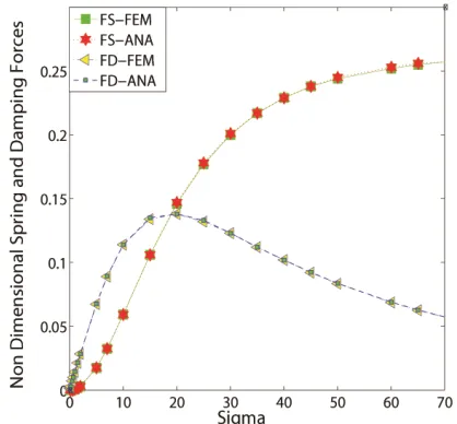
Siddartha et al. [11,12] studied the effect of varying flow boundary conditions on the squeeze film stiffness and damping for an all sides clamped micro-plate. The plate is considered to vibrate in its fundamental mode which imparts the flexibility effect. Analytical expressions have been derived for stiffness and damping forces on the plate (clamped at all sides) due to the trapped air film (subjected to different flow boundaries). We use 4 × 4 mesh for FEM modeling of the plate. We design two re- presentative flow boundary conditions with our numeri-cal scheme, namely the all four sides open (“OOOO”) and the two opposite sides closed (“OCOC”) cases. The plate is subjected to harmonic displacement boundary condition corresponding to its first mode shape. The re- sulting pressure distribution is integrated over the wet surface to get the force on the moving plate. The squeeze film spring (Fs) and damping (Fd) forces are obtained from the real and imaginary component of the resultant force respectively. The forces are non dimensionalised (see [11]) and plotted against a non dimensional parame- ter , directly related to the frequency of harmonic exci- tation as follows, 12 eff L2 / p h0 02, where μeff is the effective viscosity [13], ω is the harmonic excitation fre- quency, L is the plate side dimension, p0 is the ambient
pressure and h0 is the initial air gap. Figure 2 shows the plots for Fs and Fd for the “OOOO” case and Figure 3
shows the same for the “OCOC” case. We see from these plots that the numerical stiffness and damping forces are in close agreement with the analytical results for both the flow boundary cases studied. We also note that the two methods show good agreement at both high and low
values (thus high and low frequencies). The deviation between the numerical and analytical results have been found to be less than 2% for both the flow boundary conditions studied here.
3.2. Modeling a Cantilever
[image:4.595.316.525.283.477.2]In order to compare our results with experimental data we have modeled a cantilever beam as per dimensions
[image:4.595.315.525.518.704.2]Figure 2. Spring and damping forces vs sigma for “OOOO” configuration.
mentioned in the work of Pandey et al. [8]. We compare the numerically obtained Quality factors (Q) for the first three modes of vibration as well as the effect of aspect ratio on the quality factor of the beam for the first mode of vibration. The beam modeled is of length 350 μm, width 22 μm, thickness 4 μm, with an initial air gap of 1.4 μm. The beam material is polysilicon with density 2330 Kg/m3, Young’s Modulus 160 GPa and Poisson’s ratio 0.22. Air is considered to be the fluid medium with the relevant property values (under standard temperature and pressure ) as follows: density ρair = 1.2 Kg/m3, dy- namic viscosity µair = 1.8 × 10⁻⁵ N.s/m2, and ambient pressure pa = 1.013 × 10⁵ Pa. In our simulations we have subjected the cantilever to a sinusoidal voltage of 1.5 V, which is well below the pull-in voltage of 6 V for the given cantilever. The input voltage has been applied as an electrostatic pressure load of magnitude 5.08 N/m2 to our FEM model for the cantilever beam, considering a parallel plate capacitor with small displacement approx- imation [14]. The beam tip velocities have been obtained from the simulations and normalized with respect to the applied voltage and plotted against frequency. The fre- quency response so obtained is shown in Figure 4. The plot shows three distinct peaks corresponding to the first three modes, and is in close agreement with a similar plot reported by Pandey et al. [8]. Q factors for different modes are obtained using half power method from the frequency response plot. Convergence study of the Q factor (Table 1) has been done using three levels of mesh refinement considering a very fine mesh (100 × 6 × 4) result as our benchmark. Q factors for sufficiently fine mesh (40 × 5 ×4 ) are compared with published results from Pandey et al. [8] in Table 2. We see that the data from the numerical simulations are in good agreement with published experimental and numerical results. We
Figure 4. Frequency response of a cantilever beam of length 350 μm, width 22 μm and thickness 4 μm.
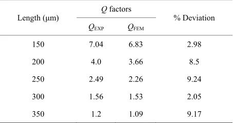
further studied beams with varying aspect ratios. We considered beams with lengths varying from 150 µm to 350 µm, having a constant width of 22 µm and thickness 4 µm. Only the first mode of vibration is considered in this study. Comparative values of Q factors for the dif- ferent beams (40 × 5 × 4 mesh) are presented in Table 3. Our simulation results show a deviation of less than 10% from the reported experimental data.
4. Conclusion
[image:5.595.309.537.489.575.2]We have discussed an FEM formulation to solve the coupled fluid-structure squeeze film problem without resorting to iterative solutions. Our results show good agreement with experimental data available from the literature. Our numerical scheme is seen to give good results for varying aspect ratio structures with dimen- sions below 100 μm. The proposed scheme can be further used as a design tool for modeling and simulation of the dynamic response of vibratory MEMS devices such as capacitive microphones, RF (Radio Frequency) MEMS switches, etc., for which accurate knowledge of the Q
Table 1. Convergence study for the first two modes of a cantilever beam of length 350 μm, width 22 μm.
[image:5.595.63.286.518.702.2]Modes Q factors for FEM Mesh (length×width×thickness) 100 × 6 × 4 40 × 5 × 4 30 × 3 × 2 20 × 3 × 2 1 1.097 1.095 1.093 1.10 2 5.842 5.849 5.891 5.908
Table 2. Q factor comparison for the first three modes of a cantilever beam of length 350 μm, width 22 μm.
Modes Q factors comparison
QEXP QANSYS QFEM
1 1.20 1.11 1.095 2 7.58 6.94 5.849 3 18.52 20.0 20.379
Table 3. Q factor comparison for beam of width 22 μm with varying lengths.
Length (μm) Q factors % Deviation
QEXP QFEM
[image:5.595.310.537.613.733.2]factor is critical for design. With this methodology one can directly couple the elasticity effect of the structure with the fluid flow and need not limit oneself to 1D geometries.
5. Acknowledgements
This work is partially supported by NPMASS grant for computational micro-systems. The authors acknowledge the support from CoNE Lab of the Center for Nano Science and Engineering at IISC.
REFERENCES
[1] M. Bao and H Yang, “Squeeze Film Air Damping in MEMS,” Sensors and Actuators A, Vol. 136, No. 1, 2007, pp. 3-27. http://dx.doi.org/10.1016/j.sna.2007.01.008
[2] R. Pratap, S. Mohite and A. K. Pandey, “Squeeze Film Effects in MEMS Devices,” Journal of the Indian Insti- tute of Science, Vol. 87, No. 1, 2007, pp. 75-94.
http://eprints.iisc.ernet.in/id/eprint/12328
[3] J. J. Blech, “On Isothermal Squeeze Films,” Journal of Lubrication Technology, Vol. 105 No. 4, 1983, pp. 615- 620. http://dx.doi.org/10.1115/1.3254692
[4] R. B. Darling, C. Hivick and J. Xu, “Compact Analytical Models for Squeeze Film Damping with Abitrary Venting Conditions,” International Conference onSolid State Sen- sors and Actuators, Vol. 2, 1997, pp. 1113-1116. http://dx.doi.org/10.1109/SENSOR.1997.635397
[5] E. S. Hung and S. D. Senturia, “Generating Efficient Dy- namical Models for Microelectromechanical Systems from a Few Finite-Element Simulation Runs,” Journal of Microelectromechanical Systems, Vol. 8, No. 3, 1999, pp. 280-289. http://dx.doi.org/10.1109/84.788632
[6] B. McCarthy, G. G. Adams, N. E. McGruer and D. Potter, “A Dynamic Model, Including Contact Bounce, of an Electrostatically Actuated Microswitch,” Journal of Mi- croelectromechanical Systems, Vol. 11, No. 3, 2002, pp. 276-283.
http://dx.doi.org/10.1109/JMEMS.2002.1007406
[7] M. I. Younis and A. H. Nayfeh, “Simulation of Squeeze- Film Damping of Microplates Actuated by Large Elec- trostatic Load,” Journal of Computational and Nonlinear Dynamics, Vol. 2, No. 3, 2007, pp. 232-240.
http://dx.doi.org/10.1115/1.2727491
[8] A. K. Pandey and R. Pratap, “Effect of Flexural Modes on Squeeze Film Damping in MEMS Cantilever Resonators,” Journal of Micromechanics and Microengineering, Vol. 17 No. 12, 2007, pp. 2475-2484.
ttp://dx.doi.org/10.1088/0960-1317/17/12/013
[9] S. D. A. Hannot and D. J. Rixen, “Coupling Plate Defor- mation, Electrostatic Actuation and Squeeze Film Damp- ing in a FEM Model of a Micro Switch,” International Conference on Computational Methods for Coupled Pro- blems in Science and Engineering, Barcelona, 2009. [10] C. S. Jog, “An Outward-Wave-Favouring Finite Element-
Based Strategy for Exterior Acoustical Problems,” Inter- national Journal of Acoustics and Vibration, Vol. 18, No. 1, 2013, pp. 27-38
http://eprints.iisc.ernet.in/id/eprint/46436
[11] S. Patra, A. Roychowdhury and R. Pratap, “Effect of Fluid Flow Boundary Conditions on Squeeze Film Para- meters of Planar MEMS Structures,” Applied Mathemat- ics Modelling, AMM 14573, Unpublished.
[12] S. Patra, “Effect of Rarefaction, Flexibility and Restric- tive Flow Boundary Conditions on Squeeze Film Flow of MEMS Devices,” Master’s Thesis, Indian Institute of Sci- ence, Bangalore, 2011.
[13] T. Veijola, H. Kuisma, J. Lahdenperä and T. Ryhänen, “Equivalent-Circuit Model of the Squeezed Gas Film in a Silicon Accelerometer,” Sensors and Actuators A: Phys- ical, Vol. 48, No. 43, 1995, pp. 239-248,
http://dx.doi.org/10.1016/0924-4247(95)00995-7