A Parallel FEA Computing Kernel for Building Structures
Jin Duan, Yungui Li, Xiaoming Chen, Hu Qi, Jianyun Sun China State Construction Technical Center, Beijing, China
Email: [email protected], [email protected]
Received August 2013
ABSTRACT
With the rapid development of high-rise buildings and long-span structures in the recent years, high performance com- putation (HPC) is becoming more and more important, sometimes even crucial, for the design and construction of com- plex building structures. To satisfy the engineering requirements of HPC, a parallel FEA computing kernel, which is designed typically for the analysis of complex building structures, will be presented and illustrated in this paper. This kernel program is based on the Intel Math Kernel Library (MKL) and coded by FORTRAN 2008 syntax, which is a parallel computer language. To improve the capability and efficiency of the computing kernel program, the parallel concepts of modern FORTRAN, such as elemental procedure, do concurrent, etc., have been applied extensively in coding and the famous PARDISO solver in MKL has been called to solve the Large-sparse system of linear equations. The ultimate objective of developing the computing kernel is to make the personal computer have the ability to analysis large building structures up to ten million degree of freedoms (DOFs). Up to now, the linear static analysis and dynamic analysis have been achieved while the nonlinear analysis, including geometric and material nonlinearity, has not been finished yet. Therefore, the numerical examples in this paper will be concentrated on demonstrating the validity and efficiency of the linear analysis and modal analysis for large FE models, while ignoring the verification of the nonlinear analysis capabilities.
Keywords: High Performance Computing; Finite Element Analysis; Building Structure; PARDISO
1. Introduction
With the rapid development of high-rise buildings and long-span structures in the recent years, high perfor- mance computation (HPC) is becoming more and more important, sometimes even crucial, for the structure de- sign and building construction.
The traditional design softwares, such as PKPM, ETABS, MIDAS, YJK and so on, can’t match the ad- vanced requirements of HPC. On the other hand, the large scale general finite element analysis (FEA) soft- wares, such as ABAQUS, ANSYS, ADINA, etc., al- though have the powerful computational abilities, but they can’t be applied directly to the architectural struc- ture analysis and design, due to the fact that their pre- processors are inconvenient for building modeling and their postprocessors can’t present computational results according to the building codes in civil engineering.
To satisfy the engineering requirements for HPC, an integrated simulation system for building structures has been designed by the authors. This system, which is a coalition of some secondary software developments toge- ther with the traditional design softwares and general FEA softwares, will provide high performance computa-
tion, simulation and technical supports for the design and construction of the large and complex buildings.
To achieve the above objectives, there are many im- portant technical indicators to be considered seriously, typically the following aspects: 1) data transformation from the structural model to FEA model; 2) parallel FEA computing kernel developed specially for the building structures and serving as the supplements to the general FEA softwares.
In this paper, the above mentioned computing kernel will be presented and discussed using some numerical examples. This FEA computing program is based on the Intel Math Kernel Library (MKL) and coded by FOR- TRAN 2008 syntax, a parallel computer language. To improve its capability and efficiency, the parallel con- cepts of modern FORTRAN, such as elemental proce- dure, do concurrent, etc., have been applied extensively in coding. And furthermore, the famous PARDISO solv- er in MKL will be called to solve the Large-sparse sys- tem of linear equations.
2. Parallel Syntax in Modern Fortran [1,2]
been designed for parallel processing.
2.1. Elemental Procedure
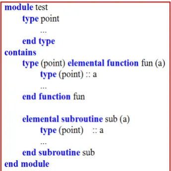
Elemental procedures are written with all scalar dummy arguments. When called with array actual arguments, the compiler will automatically call the procedure for each array element. A typical example is presented in the Fig- ures 1 and 2.
2.2. Do Concurrent
The do concurrent statement is an explicit way to indi- cate that a specific doloop may have its iterations per- formed in parallel. In this sense, it is a simplified version of the OpenMP parallel do directive that indicates the same task. It is the most appropriate for shared memory systems when enhancing existing doloops, when array syntax would cause the creation of temporary arrays, or as a replacement for all constructs. Here is an example of the do concurrent construct, shown in Figure 3.
2.3. Coarray
Coarray, maybe is abbreviated from “concurrent array”, is a new feature that Fortran 2008 introduces. The coar- ray extension adopts the Single Program Multiple Data (SPMD) programming model, i.e., a single program is replicated into multiple “images”. Animage can be thought
Figure 1. Definition of elemental procedure.
Figure 2. Calling of elemental procedure.
of as what we have referred up to now as a process envi- ronment (PE). Coarray can be thought of as a simplified and integrated alternative to MPI. The coarray model sup- ports both shared memory and distributed memory hard- ware. Figure 4 presents a typical application of coarray.
3. Pardiso Solver
Solving linear systems of equations lies at the heart of many problems in computational science and engineering, particularly in finite element analysis (FEA), because the FEA system is often very large and the associated matrix A is sparse. Among the currently-available software packages for the direct solution of sparse linear systems of equations, PARDISO (Parallel Sparse Direct Solver), coded by O. SchenkandK. Gartner [3,4] with fortran and c, maybe the most popular one, partly because it has been integrated into the math kernel library (MKL) of Intel Parallel Studio.
The PARDISO package is a high-performance, robust, memory-efficient and easy to use software for solving large sparse symmetric and non-symmetric linear sys- tems of equations. Its most remarkable characteristic is parallel computing, not only for the shared-memory ar- chitectures but also for the distributed-memory architec- tures.
4. Numerical Examples
Because the nonlinear analysis, including geometric and material nonlinearity, has not been finished yet by now, the numerical examples in the follow → followi ng will be concentrated on demonstrating the validity and effi- ciency of the linear analysis and modal analysis forlarge- scale FE models, while ignoring the nonlinear analysis
[image:2.595.86.259.426.599.2]Calling pure procedure
[image:2.595.319.525.505.720.2]Figure 3. Illustration of do concurrent.
capabilities.
[image:3.595.339.487.83.254.2]4.1. Static Analysis of a Cubesubjected to Gravity Load
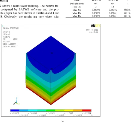
Figure 5 shows a cubic model subjected to gravity load and with bottom fixed. The comparing of the static anal- ysis results with ANSYS software and the computing program of this paper has been illustrated in Table 1 and
Figure 6. Obviously, the results are in good agreement with each other.
To verify the validity and efficiency of this computing program furthermore, Table 2 gives the displacement results of the cube with different mesh size. It can be observed that the displacement results will increase slightly with the mesh size decrease → decreases, and finally arrive at the convergence state. This phenomenon is in accordance with the FEA theory.
4.2. Natural Frequency Analysis of a Multitower Building
Figure 7 shows a multi-tower building. The natural fre- quency computed by SATWE software and the pro- gram in this paper has been shown in Tables 3 and 4 and
Figure 8. Obviously, the results are very close, with
G
Length of side:100;
Density:7800;E:5.75e8;V: 0.3; Loaded by gravity;Fixed bottom
Figure 5. Cubic model.
Table 1. Results compared with ANSYS.
ANSYS This paper Error
Mesh 50*50*50 50*50*50 --
Dofs (million) 0.4 0.4 --
Time (m) 3 1.5 --
Max_Uz 0.65398 0.65376 0.03%
Max_Ux 0.13075 0.13061 0.11%
Max_Uy 0.13075 0.13061 0.11%
[image:3.595.89.528.324.733.2](b)
Figure 6. (a) Displacement-contour plot of ANSYS; (b) Displacement-contour plot of this paper.
Table 2. Results of the cube with different mesh size.
mesh Dof (Million) Time (minutes) Max_Uz
50*50*50 0.4 1.5 0.65376
60*60*60 0.7 4 0.65386
70*70*70 1.1 15 0.65392
80*80*80 1.6 30 0.65397
90*90*90 2.2 70 0.65400
100*100*100 3.1 130 0.65403
[image:4.595.156.443.78.331.2]Figure 7. Multi-tower building.
Table 3. Computing scale and time compared with SATWE.
SATWE This paper
Mesh size (m) 1.5 1.5
Slab model Rigid Elastic
Dofs (million) 0.6 1.5
Dynamic dofs 690 500,000
Time (m) 10 10
Table 4. Results compared with SATWE.
SATWE This paper Error
Freq (Hz) 1st, 30th
0.26 0.24 7.7%
1.79 1.65 7.8%
Effective mass coefficient 0.60 (x) 0.61 (x) 1.7% 0.62 (y) 0.63 (y) 1.6%
0 5 10 15 20 25 30
0.2 0.4 0.6 0.8 1.0 1.2 1.4 1.6 1.8 2.0
F
req (
H
z)
No. of freq this paper(elastic slab) Satwe(rigid slab)
0 5 10 15 20 25 30
0.2 0.4 0.6 0.8 1.0 1.2 1.4 1.6 1.8 2.0
F
req (
H
z)
[image:4.595.58.283.374.712.2]No. of freq this paper(elastic slab) Satwe(rigid slab)
[image:4.595.307.538.387.724.2]the maximum error 7% - 8% approximately, which may- be resulted from the following reasons: 1) the FE DOFs scale of this model has exceeded the capacity of SATWE software, so the rigid slab hypothesis is introduced to decrease the DOFs scale of SATWE; 2) the SATWE software has introduced penalty function to simulate the restraints between the beams and walls, which is ignored in the program of this paper; 3) the lumped-mass models for the SATWE software and the present program are not identical, because the SATWE software has the mass of components, e.g. walls, beams, columns, braces etc., lumped at the top of itself.
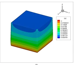
For the multi-tower building shown in Figure 7, if the mesh size is set to 1.5 m, the DOFs scale will be 1.6 mil- lion; if the mesh size is set to a smaller one, the DOFs scale will get much larger; when the mesh size decreases to 0.5 m, the DOFs scale will increase to 11 million. The modal analysis results with the above different mesh size by the present program has been shown in the Table 5
[image:5.595.317.527.84.249.2]and Figures 9 and 10. Observing the results, it can be easily concluded that the natural frequencies will de- crease with the mesh size decreasing and finally arrive at a convergence state. This conclusion is exactly coinci- dent with FEA theory.
Table 5. Results for the building with different mesh size.
Mesh Size(m) Dofs (million) Time (minutes) Freq(Hz) (1st, 30th)
1.5 1.6 3.5 0.2364 1.6316
1.2 2 4.5 0.2321 1.5926
1.0 3.1 6.0 0.2256 1.5409
0.8 4.7 55 0.2200 1.4800
0.5 11 90 0.2156 1.4375
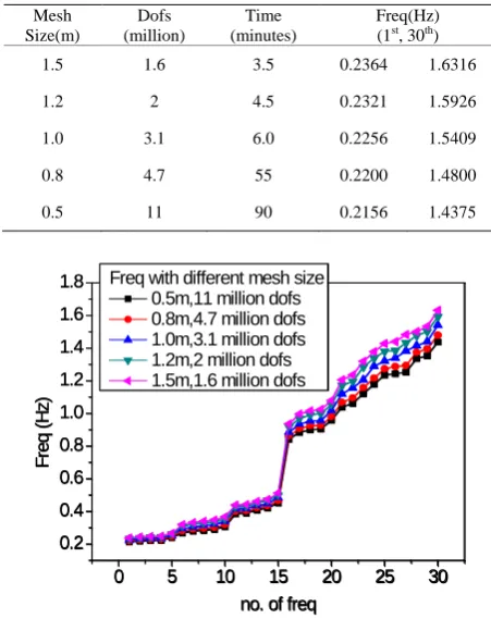
0 5 10 15 20 25 30
0.2 0.4 0.6 0.8 1.0 1.2 1.4 1.6 1.8 F req ( H z)
no. of freq Freq with different mesh size
0.5m,11 million dofs 0.8m,4.7 million dofs 1.0m,3.1 million dofs 1.2m,2 million dofs 1.5m,1.6 million dofs
0 5 10 15 20 25 30
0.2 0.4 0.6 0.8 1.0 1.2 1.4 1.6 1.8 F req ( H z)
no. of freq Freq with different mesh size
0.5m,11 million dofs 0.8m,4.7 million dofs 1.0m,3.1 million dofs 1.2m,2 million dofs 1.5m,1.6 million dofs
Figure 9. Frequency with different mesh size.
0 5 10 15 20 25 30
0 2 4 6 8 10 12 14 16 18 20 1.0m 1.5m 1.2m 0.8m 0.8m F re q e rro r (% )
No. of freq
Freq error with different mesh size
0.5m ( reference value)
0 5 10 15 20 25 30
0 2 4 6 8 10 12 14 16 18 20 1.0m 1.5m 1.2m 0.8m 0.8m F re q e rro r (% )
No. of freq
Freq error with different mesh size
0.5m ( reference value)
Figure 10. Frequency-error with different mesh size.
5. Conclusion
All the test work of this paper is on a personal computer of the author. The main hardware parameters are as fol- lows: 4-processor CPU with 3.1 GHz, 16 G RAM, WIN7-x64 OS. Therefore, it can be concluded at least partially that the FEA computing kernel presented in this paper has the ability to analysis large building structures up to ten million DOFs, using personal computer instead of workstation.
REFERENCES
[1] ISO/IEC, “F2008 Working Document,” 2008.
[2] S. Norman, “Clermanand Walter Spector. Modern Fortran Style and Usage,” Cambridge University Press, Cambri- dge, 2012.
[3] O. Schenk, K. Gartner and W. Fichtner, “Efficient Sparse LU Factorization with Left-Right Looking Strategy on Shared Memory Multiprocessors,” BIT Numerical Mathe- matics, Vol. 40, No. 1, 2000, pp. 158-176.
[4] O. Schenk and K. Gartner, “On Fast Factorization Pivot- ing Methods for Symmetric Indefinite Systems,” Elec- tronic Transactions on Numerical Analysis, Vol. 23, 2006, pp. 158-179.
[image:5.595.57.283.399.684.2]