http://dx.doi.org/10.4236/jfcmv.2016.42005
How to cite this paper: Fujisawa, K. and Asada, A. (2016) Nonlinear Acoustic Shadow Method to Reduce Reverberation Ar-tifact. Journal of Flow Control, Measurement & Visualization, 4, 49-55. http://dx.doi.org/10.4236/jfcmv.2016.42005
Nonlinear Acoustic Shadow Method to
Reduce Reverberation Artifact
*
Kei Fujisawa1, Akira Asada2
1Department of Ocean Technology, Policy and Environment, The University of Tokyo, Tokyo, Japan 2Institute of Industrial Science, The University of Tokyo, Tokyo, Japan
Received 10 December 2015; accepted 4 February 2016; published 22 April 2016
Copyright © 2016 by authors and Scientific Research Publishing Inc.
This work is licensed under the Creative Commons Attribution International License (CC BY).
http://creativecommons.org/licenses/by/4.0/
Abstract
A novel technique for reducing reverberation artifact in acoustic shadow imaging using nonlinear ultrasound interaction, called nonlinear acoustic shadow method, has been developed and expe-rimentally studied. In this technique, the conventional acoustic shadow method is modified by us-ing the secondary wave generated by nonlinear interaction of two primary sound waves emitted from parametric array. Either conventional or nonlinear acoustic shadow imaging is carried out for aluminum square cylinder and the size of the shadow is compared. The result shows that the nonlinear acoustic shadow method reduces reverberation artifact inside the square cylinder and has better accuracy in the size measurement than conventional acoustic shadow method.
Keywords
Acoustic Shadow Method, Reverberation Artifact, Nonlinear Ultrasound, Parametric Array, Secondary Wave
1. Introduction
characteristics, it has been applied to a detection of flaw defects and a characterization of materials [5]-[8]. However reverberation artifact is repeatedly occurred in the measurement due to the acoustic impedance differ-ence between the target and water, especially when transducer and hydrophone receiver are located vertical to the surface of the target and it causes virtual image of the target material [9]. In order to reduce the reverberation artifact in acoustic shadow imaging, the sound pressure of the transmitter can be reduced or the transducer can be inclined to the target surface, while the signal amplitude of imaging is reduced and causes lower SNR (signal to noise ratio) in acoustic shadow imaging. Therefore, the reducing reverberation artifact is an important topic in the application to underwater measurement and material characterization in comparison with the medical appli-cation due to higher environmental and machinery noise. Furthermore, it is difficult to estimate the incident an-gle of the beam to the target in the underwater measurement.
The purpose of this paper is to study the experimental technique using the secondary waves generated by non-linear interaction of ultrasonic wave emitted from parametric array for reducing reverberation artifact in acoustic shadow imaging. Then, the results are compared with those of the conventional acoustic shadow method that utilizes the primary waves.
2. Experiment
We introduced secondary wave generated from parametric array to reduce reverberation artifact of acoustic shadow imaging in water. When two different frequency of sound waves (primary waves) are transmitted in the same direction, the secondary wave such as sum and difference frequencies are generated by nonlinear interac-tion of finite amplitude waves [10] [11]. This acoustic technique has been reported by many previous papers for its acoustic characteristic such as high directivity with low side-lobe beam. Especially, it has been used with pulse echo method in underwater imaging [12]-[16] and underwater acoustic communication [17].
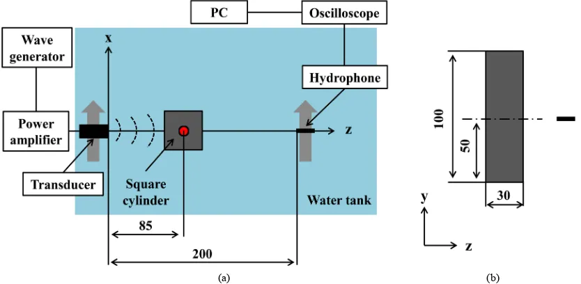
The experiments were carried out for acoustic shadow imaging of square cylinder made of aluminum, which is summarized in Figure 1(a), Figure 1(b). The water tank was 600 mm long and 500 mm wide with 500 mm deep, and the water temperature was maintained at 298 K by temperature control unit. Both the transducer and hydrophone used in the experiment were circular type with flat surface. The size of the transducer was 12 mm in diameter and that of the hydrophone was 6 mm in diameter. It should be mentioned that hydrophone potentially has space averaging error in measurement, and such error may be reduced by smaller size of the hydrophone. However smaller size hydrophone also reduces the sensitivity and has difficulty in measuring the secondary waves which has lower signal level than that of the primary waves. The center point of the square cylinder was located at the axial position z = 85 mm from the transducer in water and the hydrophone was located at z = 200 mm from the transducer on beam axis. The transducer and hydrophone were traversed in the same direction
[image:2.595.106.523.487.691.2](a) (b)
across the square cylinder and the hydrophone was set a) vertical to the square cylinder and b) 45 degree to square cylinder, which allows the detection of the acoustic signal from the transducer influenced by the presence of the square cylinder and reconstructs two-dimensional acoustic image as shown in Figure 2(a), Figure 2(b), respectively. The sampling of the acoustic signal was carried out by traversing the transducer and hydrophone for every 1 mm across the target by three-dimensional positioning stage. Then, the shadow image of signal am-plitude distribution was generated.
The transducer was excited by two different frequencies of primary waves and the driving signal s is written by the following equation,
(
)
(
)
(
)
0 sin 2 1 sin 2 2 0
s s= πf t+ πf t+π < <t tr (1) where s0 is the signal amplitude of primary waves and t is a time. The two frequency of primary waves were set
f1 = 2 MHz and f2 = 2.4 MHz with transmittance time of tr= 2.5 μs. The signal was observed by the digital sto-rage oscilloscope, where the spurious reflections were eliminated using the time gate, and the received signal was averaged over 64 times at each position to minimize the white noise in this measurement. The sound pres-sure was meapres-sured using the receiver hydrophone which had flat frequency response within ±3 dB over the fre-quency range from 2 MHz to 8 MHz. Note that the initial time of signals recorded by hydrophone is set as a time when acoustic wave is transmitted from transducer.
3. Result
3.1. Nonlinear Sound Propagation through Square Cylinder
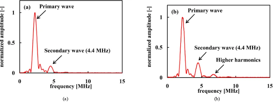
Figure 3(a), Figure 3(b) show the frequency spectrum of the sound signal detected by the hydrophone located
[image:3.595.96.533.375.482.2](a) (b)
Figure 2. Arrangement of square cylinder and hydrophone (unit in mm). (a) Vertical to square cylinder; (b) 45 degree to square cylinder.
(a) (b)
[image:3.595.90.540.518.688.2]at z = 200 mm with and without square cylinder, respectively. The center of the square cylinder is on the beam axis and the hydrophone is set behind the square cylinder, which is the vertical case in Figure 2(a). The same input voltage was applied to the transducer in both cases and the frequency spectrum of the sound wave was evaluated using discrete Fourier transform, and the frequency spectrum is normalized by each maximum signal amplitude of the signal. Note that the signal level of the primary waves is reduced to 1/5 by the influence of the square cylinder, while that of the secondary wave is reduced more strongly. The results of the normalized pres-sure amplitude show the generation of secondary wave at the sum frequency (centered at f = 4.4 MHz) due to the nonlinear interaction of finite amplitude sound propagation. It should be mentioned that the relative pressure amplitude of the secondary wave with square cylinder is almost half amplitude of the case without square cy-linder. Furthermore, the pressure amplitude at higher harmonics (centered at f = 6.8 MHz) shows a similar trend as the secondary wave with and without square cylinder. These results indicate that acoustic shadow imaging using secondary wave can be applied to eliminate the small amplitude phenomena in imaging, such as the re-verberation artifact in acoustic shadow method, when the secondary wave is properly amplified.
3.2. Nonlinear Acoustic Shadow Imaging
To verify the application effects of nonlinear acoustic shadow method, we investigated the noninvasive detec-tion of the square cylinder using nonlinear acoustic shadow method that utilizes secondary wave in water. For the comparative purposes, linear acoustic shadow imaging was carried out by removing secondary wave by low-path filter with the cut-off frequency 3.3 MHz. Note that the linear acoustic shadow imaging corresponds to the conventional acoustic shadow method that utilizes primary waves. Finally, the two-dimensional acoustic shadow images were reconstructed by traversing the transducer and hydrophone across the square cylinder after detecting the envelope of each waves by Hilbert transformation [18]-[20]. These images were normalized by each maximum amplitude that corresponds to the direct wave.
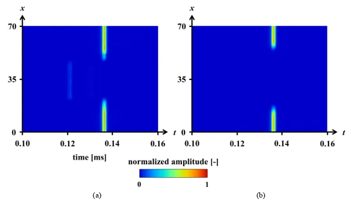
Figure 4(a) and Figure 4(b) show the linear acoustic shadow images of two different arrangements of hy-drophone to square cylinder, respectively. These are the cases of beam axis vertical to square cylinder (Figure 4(a)) and 45 degree to square cylinder (Figure 4(b)). There are three kinds of signal distributions, which are numbered in 1, 2 and 3 in Figure 4(a). These are the penetration wave through square cylinder, reverberation waves inside the square cylinder and the direct waves, respectively, while Figure 4(b) shows no reverberation artifact in acoustic shadow image due to large incident angle of the beam to the square cylinder.
Figure 5(a) and Figure 5(b) show the nonlinear acoustic shadow images of two different arrangements of square cylinder and hydrophone, respectively. These are vertical to square cylinder (Figure 5(a)) and45 degree to square cylinder(Figure 5(b)). There is a tendency of nonlinear acoustic shadow image to have shaper outline compared to linear acoustic shadow image due to the shorter wave length of the secondary wave than that of the primary waves [21], which are commonly observed in these results. The signal level of penetration wave and reverberation wave are greatly suppressed in the image using nonlinear acoustic shadow method in Figure 5(a) compared to that of linear acoustic shadow method shown in Figure 4(a). This is true for the case of 45 degree to square cylinder in Figure 5(b).
In order to verify the size measurement accuracy of nonlinear acoustic shadow method, the error of measure-ment is introduced as follows,
0 s L L
ε= − (2)
where Ls and L0 are the side lengths measured by acoustic shadow method and actual size, respectively. Note
(a) (b)
Figure 4. Linear acoustic shadow image of square cylinder (1: penetration wave; 2: reverberation wave; 3: direct wave). (a) Vertical to square cylinder; (b) 45 degree to square cylinder.
[image:5.595.131.493.315.522.2](a) (b)
Figure 5. Nonlinear acoustic shadow image of square cylinder. (a) Vertical to square cylinder; (b) 45 degree to square cylinder.
(a) (b)
[image:5.595.89.538.546.705.2]4. Conclusion
Nonlinear acoustic shadow method that utilizes the secondary wave of parametric array is newly developed for the noninvasive detection of solid structure in water. The experiments are carried in water with and without square cylinder and the result shows that larger variation of relative signal is observed through structure in the secondary wave than the primary waves. It is also observed that the reverberation artifact is reduced and the measurement accuracy is improved in the nonlinear acoustic shadow method using the secondary wave. These results show the capability of lower artifact with higher accuracy for the target object detection by nonlinear acoustic shadow imaging using parametric array, and might lead to a wider application of ultrasound in under-water imaging.
References
[1] Blitz, J. and Simpson, G. (1996) Ultrasonic Methods of Non-Destructive Testing. Vol. 2, Springer Science and Busi-ness Media, Berlin.
[2] Wróbel, G. and Pawlak, S. (2007) A Comparison Study of the Pulse Echo and Through-Transmission Ultrasonics in Glass/Epoxy Composites. Journal of Achievements in Materials and Manufacturing Engineering, 22, 51-54.
[3] Tattersall, H.G. (1973) The Ultrasonic Pulse-Echo Technique as Applied to Adhesion Testing. Journal of Physics D:
Applied Physics, 6, 819. http://dx.doi.org/10.1088/0022-3727/6/7/305
[4] Krautkrämer, J. and Krautkrämer, H. (2013) Ultrasonic Testing of Materials. Springer Science and Business Media, Berlin.
[5] Purnell, P., Gan, T.H., Hutchins, D.A. and Berriman, J. (2004) Noncontact Ultrasonic Diagnostics in Concrete: A Pre-liminary Investigation. Cement and Concrete Research, 34, 1185-1188.
http://dx.doi.org/10.1016/j.cemconres.2003.12.012
[6] Song, H.W. and Saraswathy, V. (2007) Corrosion Monitoring of Reinforced Concrete Structures-A. International Journal of Electrochemical Science, 2, 1-28.
[7] Pinton, G., Aubry, J.F., Bossy, E., Muller, M., Pernot, M. and Tanter, M. (2012) Attenuation, Scattering, and Absorp-tion of Ultrasound in the Skull Bone. Medical Physics, 39, 299-307. http://dx.doi.org/10.1118/1.3668316
[8] Chimenti, D.E. (2014) Review of Air-Coupled Ultrasonic Materials Characterization. Ultrasonics, 54, 1804-1816.
http://dx.doi.org/10.1016/j.ultras.2014.02.006
[9] Feldman, M.K., Katyal, S. and Blackwood, M.S. (2009) US Artifacts 1. Radiographics, 29, 1179-1189.
http://dx.doi.org/10.1148/rg.294085199
[10] Westervelt, P.J. (1963) Parametric Acoustic Array. The Journal of the Acoustical Society of America, 35, 535-537.
http://dx.doi.org/10.1121/1.1918525
[11] Gan, W., Yang, J. and Kamakura, T. (2012) A Review of Parametric Acoustic Array in Air. Applied Acoustics,73, 1211-1219. http://dx.doi.org/10.1016/j.apacoust.2012.04.001
[12] Berktay, H.O. (1965) Possible Exploitation of Non-Linear Acoustics in Underwater Transmitting Applications. Journal of Sound and Vibration, 2, 435-461. http://dx.doi.org/10.1016/0022-460X(65)90122-7
[13] Tjo, J.N., Tjo, S. and Vefring, E.H. (1990) Propagation and Interaction of Two Collinear Finite Amplitude Sound Beams. The Journal of the Acoustical Society of America, 88, 2859-2870. http://dx.doi.org/10.1121/1.399690
[14] Edwards, J.R., Schmidt, H. and Le Page, K.D. (2001) Bistatic Synthetic Aperture Target Detection and Imaging with an AUV. IEEE Journal of Oceanic Engineering, 26, 690-699. http://dx.doi.org/10.1109/48.972112
[15] Nomura, H., Hedberg, C.M. and Kamakura, T. (2012) Numerical Simulation of Parametric Sound Generation and Its Application to Length-Limited Sound Beam. Applied Acoustics, 73, 1231-1238.
http://dx.doi.org/10.1016/j.apacoust.2012.02.016
[16] Fujisawa, K. and Asada, A. (2015) Nonlinear Sound Propagation on Acoustic Phased Array. Applied Acoustics, 95, 57- 59. http://dx.doi.org/10.1016/j.apacoust.2015.02.014
[17] Yin, J., Zhang, X. and Zhou, Y. (2015) Differential Pattern Time Delay Shift Coding Underwater Acoustic Communi-cation Using Parametric Array. The Journal of the Acoustical Society of America, 137, 2214.
http://dx.doi.org/10.1121/1.4920066
[18] Hoseini, M.R., Wang, X. and Zuo, M.J. (2012) Estimating Ultrasonic Time of Flight Using Envelope and Quasi Maxi-mum Likelihood Method for Damage Detection and Assessment. Measurement, 45, 2072-2080.
http://dx.doi.org/10.1016/j.measurement.2012.05.008
on Ultrasound Images. Medical Image Analysis, 16, 1073-1084. http://dx.doi.org/10.1016/j.media.2012.05.001
[20] Mari, J.M. and Cachard, C. (2007) Acquire Real-Time RF Digital Ultrasound Data from a Commercial Scanner. Elec-tronic Journal: Technical Acoustics, 3, 1-16.
[21] Humphrey, V.F. (2000) Nonlinear Propagation in Ultrasonic Fields: Measurements, Modelling and Harmonic Imaging.
Ultrasonics, 38, 267-272. http://dx.doi.org/10.1016/S0041-624X(99)00122-5
Nomenclature
f: frequency [Hz]
f1, f2: two frequency of primary waves [Hz], Equation (1)
L0: side length of square cylinder [mm]
LS: side length measured by acoustic shadow method [mm] s:driving signal [V] , Equation (1)
s0: signal amplitude [V]
t: time [s]
tr: transmittance time [s]
x, y, z: coordinates [mm], Figure 1