M
>ROGRAMS FOR DATA PROCESSIN
AT THE ACCELERATORS OF THE
CENTRAL BUREAU FOR NUCLEAR MEASUREMENTS
PART 2 : INTERRUPT SERVICING PROGRAMS FOR DATA HANDLING
AND REDUCTION
nmît
,iw- «
Η. HORSTMANN and F. COLLING
s í í s s v WrFs liPiì •ífcPi8k
,*¿
I«
I "ΕίΛΙΪΊ ''',.'■ S'ci;, fi'!' - All· #*ieiJ t ^ T ^ M i l f T * * fff·»11
This document was prepared under the sponsorship of the Commission
of the European Communities.
■Mmü
"";/!&'' ι!
\ΛΓ*
Neither the Commission of the European Communities, its contractors
nor any person acting on their behalf :
#$3"
"riöMJi
make any warranty or representation, express or implied, with respect
to the accuracy, completeness, or usefulness of the information contained
in this document, or that the use of any information, apparatus, method
or process disclosed in this document may not infringe privately owned
rights; or
m
- WMMË
assume any liability with respect to the use of, or for damages resulting
from the use of any information, apparatus, method or process disclosed
in this document.
Rif
Hi
MMMMKV.IÉT
'
"^Ηώΐ'
¥S
ì^^r"C,CTW · Ι^
?!Β«
This report is oi
li»>ieii:Ssl»III»ii
ι on sale at the addresses Usted on cover page 4
a
U
at the
P
rice of E F r
·
2 5 0
-which are indicated on the cover
of
each report
XViAfi
lfe*fpl
II» IlÄfMielii
li
When ordering, please quote the
EUR
number and the title
Mi W c τ * »! OTÌPVHAUWïuvot s.a.
... Brussels
Luxembourg, March 1972
lie
i'l'W !'tW>*fThis document was reproduced on the basis of the best available copy.
EUR 4404 e — Part 2
IBM 1800 PROGRAMS FOR DATA PROCESSI XG AT THE ACCELERATORS OF THE CENTRAL BUREAU FOR NUCLEAR MEASUREMENTS
Part 2 : Interrupt servicing programs for data handling and reduction
by H. HORSTMANN and F. COLLING
European Atomic Energy Community - EURATOM
Joint Nuclear Research Centre - Geel Establishment (Belgium) Central Bureau for Nuclear Measurements - CBNM
Luxembourg, March 1!)72 - 182 Pages - 2 Figures - B.l-'r. 250.—
This report describes a set of interrupt servicing programs for data transfers from a number of data acquisition stations at a Van de Graaff and an electron linear accelerator to an IBM 1800 computer. Furthermore it contains a descrip-tion of several test routines which can be used to cheek the funcdescrip-tional character-istics of the interface units connecting the data acquisition stations to the computer. The data acquisition stations are equipped with fast time-of-flight multi-channel analysers, and the source of most of the data to be collected and transferred to the computer are neutron cross section experiments.
EUR 4404 e — Part 2
IBM 18(H) PROGRAMS FOR DATA PROCESSING AT THE ACCELERATORS OF THE CENTRAL BUREAU FOR NUCLEAR MEASUREMENTS
Part 2 : Interrupt servicing programs for data handling and reduction
by H. HORSTMANN and 1'. COLLING
European Atomic Energy Community - EURATOM
Joint Nuclear Research Centre - Geel Establishment (Belgium) Central Bureau for Nuclear Measurements - CBNM
Luxembourg, March 1972 - 1S2 Pages - 2 Figures - B.Fr. 250.—
This report describes a set of interrupt servicing programs for data transfers from a number of data acquisition stations at a Van de Graaff and an electron linear accelerator to an IBM 1800 computer. Furthermore it: contains a descrip-tion of several test routines which can be used to check the funcdescrip-tional character-istics of the interface units connecting the data acquisition stations to the computer. The data acquisition stations are equipped with fast time-of-flight multi-channel analysers, and the source of most of the data to be collected and transferred to the computer are neutron cross section experiments.
EUR 4404 e — Part 2
IBM 1SO0 PROGRAMS FOR DATA PROCESSING AT THE ACCELERATORS OF THE CENTRAL BUREAU FOR NUCLEAR MEASUREMENTS
Part 2 : Interrupt servicing programs for data handling and reduction
by 11. HORSTMANN and 1·". COLLING
European Atomic Energy Community - EURATOM
Joint Nuclear Research Centre - Geel establishment (Belgium) Central Bureau for Nuclear Measurements - CBNM
Luxembourg, March 1972 - 182 Pages - 2 Figures - lì. IT. 250.—
Besides controlling the data transfers between the analysers and the disk storage of the computer several programs also perform data reduction procedures, especially for total cross section measurements.
All programs are written in ASSEMBLER language for the Time-Sharing Executive System (TSX).
Besides controlling the data transfers between the analysers and the disk storage of the computer several programs also perform data reduction procedures, especially for total cross section measurements.
All programs are written in ASSEMBLER language for the Time-Sharing Executive System (TSX).
Besides controlling the data transfers between the analysers and the disk storage of the computer several programs also perform data reduction procedures, especially for total cross section measurements.
EUR 4 4 0 4 e
P A R T 2
E U R O P E A N ATOMIC E N E R G Y COMMUNITY - EURATOM
IBM 1800 PROGRAMS FOR DATA PROCESSING
AT THE ACCELERATORS OF THE
CENTRAL BUREAU FOR NUCLEAR MEASUREMENTS
P A R T 2 : I N T E R R U P T SERVICING PROGRAMS FOR DATA HANDLING
AND REDUCTION
by
H. HORSTMANN and F. COLLING
1972
Joint Nuclear Research Centre
Geel Establishment - Belgium
A B S T R A C T
This report describes a set of interrupt servicing programs for data transfers from a number of data acquisition stations at a Van de Graaff and an electron linear accelerator to an IBM 1800 computer. Furthermore it contains a descrip-tion of several test routines which can be used to check the funcdescrip-tional character-istics of the interface units connecting the data acquisition stations to the computer. The data acquisition stations are equipped with fast time-of-flight multi-channel analysers, and the source of most of the data to be collected and transferred to the computer are neutron cross section experiments.
Besides controlling the data transfers between the analysers and the disk storage of the computer several programs also perform data reduction procedures, especially for total cross section measurements.
All programs are written in ASSEMBLER language for the Time-Sharing Executive System (TSX).
KEYWORDS
PROGRAMMING
LINEAR ACCELERATORS
VAN DE GRAAFF ACCELERATORS
DATA ACQUISITION SYSTEMS
ON-LINE COMPUTERS
RECORDING SYSTEMS
MULTI-CHANNEL ANALYSERS
NEUTRONS
3
-CONTENTS
Page
1. INTRODUCTION 5
2. FUNCTIONAL CHARACTERISTICS OF THE
ANALYZER COMPUTER INTERFACE UNITS
3. FORMAT SPECIFICATIONS FOR ANALYSER
DATA AND CONTROL INFORMATION OF
THE INTERFACE UNIT
4. DESCRIPTION OF THE INTERRUPT SERVICING 11
PROGRAM S UMON
5. TEST AND UTILITY PROGRAMS 21
6. REFERENCES 27
- 5
1. Introduction *)
The integrated data p r o c e s s i n g s y s t e m (Fig. l) of the Central
Bureau for Nuclear M e a s u r e m e n t s (CBNM) has mainly been
installed for neutron c r o s s section m e a s u r e m e n t s at a 90 MeV
electron l i n e a r a c c e l e r a t o r and a 3 MV Van de Graaff. The
system is based on an IBM 1800 computer (32 K, 2 μ sec cycle
t i m e , 4 disk d r i v e s : IBM 1810/A3 and 1810/A1, 3 magnetic
tapes IBM 2401) to which seven data acquisition stations a r e
connected by special interface units.
Six of t h e s e data acquisition stations a r e equipped with fast
time-of-flight multi - channel a n a l y s e r s (five of them having
4096 and one 1600 channels) and one with a GA 18/30 satellite
c o m p u t e r .
The a n a l y s e r computer interface units r e q u e s t computer i n t e r
rupts for data t r a n s f e r s either automatically according to p r e s e t
e x p e r i m e n t a l conditions or by o p e r a t o r intervention. Having a c
cepted an i n t e r r u p t the computer controls the data t r a n s f e r by
sending special commands to and receiving status information
from the corresponding interface unit, i. e. the computer takes
over complete control of the data t r a n s f e r . Several validity
checks a r e made on the t r a n s f e r r e d data before they a r e stored
into general disk files which a r e used l a t e r on for interactive
data reduction and n u m e r i c a l analysis with r e s p e c t to i n t e r e s t i n g
physical p a r a m e t e r s .
This r e p o r t d e s c r i b e s the i n t e r r u p t servicing p r o g r a m s controlling
the data t r a n s f e r s from the m u l t i - c h a n n e l a n a l y s e r s to the IBM
1800 computer and the subsequent data storage on disk. In s e v e r a l
c a s e s the disk storage operations a r e p r e c e d e d by data reduction
p r o c e d u r e s , especially for neutron total c r o s s section data.
F u r t h e r m o r e this r e p o r t contains a description of s e v e r a l test
routines which can be used to check the functional c h a r a c t e r i s t i c s
of the a n a l y s e r computer interface units in case of defects. All
p r o g r a m s a r e written in ASSEMBLER language for the T i m e
-Sharing Executive System (TSX). P r o g r a m s supporting other
features of the CBNM integrated data p r o c e s s i n g system, such
as interactive data reduction by m e a n s of the interface units,
satellite computer operation, off-line data reduction and analysis,
a r e r e p o r t e d e l s e w h e r e ((l), (2), (3), (4), (5), (6)).
2 . F u n c t i o n a l C h a r a c t e r i s t i c s of t h e A n a l y s e r C o m p u t e r I n t e r f a c e
U n i t s
F o r a d e t a i l e d d e s c r i p t i o n of t h e i n t e r f a c e u n i t s c o n n e c t i n g m u l t i
c h a n n e l a n a l y s e r s t o t h e IBM 1800 c o m p u t e r t h e r e a d e r i s r e f e r r e d
to (7), (8). O n l y t h e m a i n f u n c t i o n a l c h a r a c t e r i s t i c s of t h e i n t e r f a c e
u n i t s w i l l be o u t l i n e d h e r e .
E a c h a n a l y s e r c o m p u t e r i n t e r f a c e u n i t c o n t a i n s a m e m o r y of four
r e a d - o n l y c o n t r o l w o r d s a n d n i n e c o u n t i n g r e s g i s t e r s ( s c a l e r s ) ,
i n s t r u c t i o n a n d a d d r e s s d e c o d e r s , a n d c o n t r o l c i r c u i t r y f o r t h e
s u p e r v i s i o n of t h e d a t a a c c u m u l a t i o n in t h e a n a l y s e r a n d for t h e
d a t a t r a n s f e r t o t h e c o m p u t e r . T h i s t r a n s f e r i s done b l o c k w i s e ,
e a c h b l o c k h a v i n g 2 56 c h a n n e l s . A c o n t r o l w o r d , s c a l e r w o r d , o r
a n a n a l y s e r c h a n n e l i s r e a d by t h e c o m p u t e r in t w o w o r d s of 16
b i t s e a c h .
T h e i n t e r f a c e u n i t i s o p e r a t e d b y c o m p u t e r c o m m a n d s s e n t out
t h r o u g h a 16 b i t d i g i t a l r e g i s t e r . The c o m m a n d s h a v e t h e f o l
l o w i n g f o r m a t ( F i g . 2b):
o p e r a t i o n c o d e
w o r d a d d r e s s W ( s c a l e r w o r d o r c o n t r o l w o r d )
o r a d d r e s s Β of a n a n a l y s e r b l o c k
a d d r e s s S of t h e d a t a a c q u i s i t i o n s t a t i o n
( i n t e r f a c e unit)
T h e f u n c t i o n of a n i n t e r f a c e u n i t i s e x p l a i n e d b y a d e s c r i p t i o n of
t h e i n s t r u c t i o n s e t b y w h i c h it i s c o n t r o l l e d . The b i t c o n f i g u r a t i o n
of a n i n s t r u c t i o n i s g i v e n in h e x a d e c i m a l r e p r e s e n t a t i o n (X = not
u s e d ) . A l l c o m p u t e r c o m m a n d s a r e s e n t t o t h e i n t e r f a c e u n i t v i a
a 16 bit d i g i t a l o u t p u t r e g i s t e r ( D O R I ) , a n d a l l d a t a to a n d f r o m
t h e i n t e r f a c e u n i t p a s s a 16 b i t d i g i t a l o u t p u t r e g i s t e r (DOR2) a n d
a 16 bit d i g i t a l i n p u t r e g i s t e r (DIR) r e s p e c t i v e l y .
14XS P R I N T A L P H A M E R I C
T h e c o m p u t e r i n f o r m s t h e i n t e r f a c e u n i t of s t a t i o n S
t h a t a m e s s a g e i s t o p r i n t e d o n t h e s t a t i o n t y p e w r i t e r .
The m e s s a g e i t s e l f i s t r a n s f e r r e d in d a t a c h a n n e l
o p e r a t i o n .
22WS R E A D F I R S T 16 B I T S O F W O R D W
T h e c o m p u t e r i n f o r m s t h e i n t e r f a c e u n i t of s t a t i o n S
t h a t t h e f i r s t 16 b i t s of t h e i n t e r f a c e w o r d W ( s c a l e r
w o r d o r c o n t r o l w o r d ) a r e t o b e r e a d . T h e i n t e r f a c e
u n i t s e n d s t h e r e q u i r e d i n f o r m a t i o n t o t h e i n p u t r e
g i s t e r of t h e c o m p u t e r f r o m w h e r e i t i s r e a d in d i r e c t
p r o g r a m c o n t r o l .
B i t s 0
B i t s 8
B i t s 12
-7:
11:
7
-23WS
R E A D S E C O N D 16 B I T S O F W O R D W
T h e c o m p u t e r i n f o r m s t h e i n t e r f a c e u n i t of s t a t i o n S
t h a t t h e s e c o n d 16 b i t s of t h e i n t e r f a c e w o r d W a r e
t o b e r e a d (cf. 2 2 W S ) .
24WS
W R I T E W O R D W
T h e c o m p u t e r i n f o r m s t h e i n t e r f a c e u n i t of s t a t i o n S
t h a t a c o m p u t e r w o r d i s t o b e w r i t t e n i n t o t h e f i r s t
o r s e c o n d g r o u p of 16 b i t s of t h e s c a l e r w i t h a d d r e s s W.
T h e c o m p u t e r w o r d c o n t a i n s a n i n d i c a t o r s p e c i f y i n g
a s d e s t i n a t i o n t h e f i r s t o r s e c o n d g r o u p of 16 b i t s i n
t h e s c a l e r w o r d (32 b i t s ) . R e g i s t e r D O R 2 i s u s e d f o r
t h e t r a n s f e r t o t h e i n t e r f a c e u n i t .
32BS
R E A D A N A L Y S E R B L O C K Β
T h e c o m p u t e r i n f o r m s t h e i n t e r f a c e u n i t of s t a t i o n S
t h a t t h e a n a l y s e r d a t a b l o c k w i t h a d d r e s s Β i s t o b e
r e a d . T h e d a t a b l o c k i s t r a n s f e r r e d t o t h e c o m p u t e r
i n d a t a c h a n n e l o p e r a t i o n w i t h e x t e r n a l s y n c h r o n i z a t i o n .
34BS
W R I T E A N A L Y S E R B L O C K Β
T h e c o m p u t e r i n f o r m s t h e i n t e r f a c e u n i t of s t a t i o n S
t h a t t h e a n a l y s e r d a t a b l o c k w i t h a d d r e s s Β i s t o be
w r i t t e n b y t h e c o m p u t e r . T h e d a t a b l o c k i s t r a n s f e r r e d
i n d a t a c h a n n e l o p e r a t i o n w i t h e x t e r n a l s y n c h r o n i z a t i o n .
30BS
C L E A R A N A L Y S E R B L O C K Β
T h e b l o c k w i t h a d d r e s s Β i n t h e a n a l y s e r of s t a t i o n S
i s c l e a r e d . If a l l b l o c k s w i t h t h e a d d r e s s e s B , t h r o u g h
B2 a r e t o b e c l e a r e d t h r e e c o m p u t e r o p e r a t i o n s h a v e
t o f o l l o w e a c h o t h e r i m m e d i a t e l y : 3 0 B ^ S , r e s e t of
r e g i s t e r D O R I , 3 0 B
2S .
42XS_...
R E A D W O R D S
T h e c o m p u t e r i n f o r m s t h e i n t e r f a c e u n i t of s t a t i o n S
t h a t t h e f o u r c o n t r o l w o r d s a n d t h e n i n e s c a l e r w o r d s
a r e t o b e r e a d . T h e w o r d s a r e t r a n s f e r r e d i n d a t a
c h a n n e l o p e r a t i o n w i t h e x t e r n a l s y n c h r o n i z a t i o n .
80XS
C L E A R S C A L E R S
A l l s c a l e r s i n t h e i n t e r f a c e u n i t a t s t a t i o n S a r e r e s e t
t o z e r o .
AOXS
P R I N T W O R D S
BOXS E N D O F I N T E R R U P T
T h e c o m p u t e r i n f o r m s t h e i n t e r f a c e u n i t a t s t a t i o n S
t h a t t h e i n t e r r u p t h a s b e e n s e r v i c e d .
E8XS D I S A B L E S T A T I O N S
T h e i n t e r f a c e u n i t of s t a t i o n S i s d i s a b l e d t o r e q u e s t
c o m p u t e r i n t e r r u p t s .
F 8 X S E N A B L E S T A T I O N S
The i n t e r f a c e u n i t of s t a t i o n S i s e n a b l e d to r e q u e s t
c o m p u t e r i n t e r r u p t s .
A s u m m a r y of c o m p u t e r c o m m a n d s for t h e a n a l y s e r i n t e r f a c e u n i t
i s g i v e n in F i g . 4.
F o r t h e four c o n t r o l w o r d s a n d t h e n i n e s c a l e r w o r d s in e a c h i n t e r
-f a c e u n i t t h e -following a d d r e s s a s s i g n m e n t h a s b e e n m a d e ;
A d d r e s s 0: c o n t r o l w o r d 1
111-9: s c a l e r 1-9
" A: control word 3
" B: control word 4
" C, D, E: not used
" F : control word 2
3. F o r m a t Specifications for A n a l y s e r Data and Control Information
of the Interface Unit
The e x p e r i m e n t a l data accumulated in the core m e m o r i e s of the
m u l t i - c h a n n e l a n a l y s e r s a r e in BCD format, i. e. 6 binary coded
decimal digits per channel. These data a r e t r a n s f e r r e d to the d i
-gital input r e g i s t e r (DIR) of the computer in the format shown in
F i g . 2a. F o r the control words and the s c a l e r words of the i n t e r
-face units the s a m e format is used.
The 24 bits of the 6 decimal digits of an a n a l y s e r channel or an i n t e r
-face word a r e split into two groups of 12 bits for two computer w o r d s :
BCD1, BCD2, BCD3 in the first word and BCD4, ECD5, BCD6 in the
second word. The remaining 4 bits in each 16 bit word a r e used for
control information (Fig. 2a). Details of the format specifications
a r e given below (Fig. 3).
3. 1. Analyser channels and s c a l e r words
Bit position 0 (flag bit F ) :
1. word:A l b i t i n a s c a l e r word indicates that the 6 digit s c a l e r
value has to be multiplied by 10 before it is used in
calculations.
2. word: The l a s t s c a l e r (up to 9) to be t r a n s f e r r e d to the
compu-t e r and compu-the l a s compu-t channel in each block of a n a l y s e r dacompu-ta
[image:12.595.78.523.55.496.2]9
-Bit position 1:
Odd p a r i t y of the 16 bit word.
Bit positions 2 and 3:
Bit 2 and 3 specify the first (00) or second (01) group of 3
decimal digits. By r e s e r v i n g two bits for this identification
provision has been m a d e for the t r a n s f e r of information
con-taining up to 64 bits (4 computer words). This is useful for
m u l t i p a r a m e t e r e x p e r i m e n t s .
The s c a l e r words contain information c h a r a c t e r i s i n g the e x
-p e r i m e n t a l data.
Scaler 1: This counting r e g i s t e r stops the data accumulation at
the p r e s e t monitor count defined in control word 4.
(When s c a l e r 1 stops its content should a g r e e with
control word 4).
Scaler 2: Total count of the a n a l y s e r s p e c t r u m .
Scaler 3-9:Optionally u s e d .
F o r a n a l y s e r channels and s c a l e r words BCD1 is considered as
the high o r d e r digit of a six digit n u m b e r .
3. 2. Control words
F o r bit positions 1, 2 and 3 t h e r e is no difference as compared
to the a n a l y s e r channels and s c a l e r w o r d s . Bit position 0 (F) is
explained together with a detailed description of the control w o r d s .
The a n a l y s e r m e m o r y of 4096 channels (analyser words) is r e a d
out in 16 s e p a r a t e l y a d d r e s s e d blocks of 2 56 channels each. This
group of 16 blocks is p r e c e d e d by four control words and up to
nine (flag bit J ) s c a l e r words identifying the s p e c t r u m .
The four control words contain information specifying the type of
experimental data and the d e s i r e d computer t r e a t m e n t . The i n
-formation in the control words is r e l a t e d to the experimental
equipment, the multichannel a n a l y s e r , and s e v e r a l digit switches
at the interface unit.
Control word 1 ( a d d r e s s 0)
Control word 1 specifies the s p e c t r u m identification no. (3).
1. half-word:
F = r e s e t indicator:
1 = c l e a r a n a l y s e r m e m o r y after it has been r e a d
(read d e s t r u c t i y e ) .
10
-BCDl (high order digit) ) = group no. of spectrum identification
BCD2 (low order digit) )
no.
BCD3 = 1st. experiment no.
2. half-word:
F = not used
BCD4 = 2nd. experiment no.
BCD5 (high order digit) )
. .
,
.
_ _ _ , ),
6,
, . . χ ( = serial no. of spectrum.
BCD6 (low order digit) )
^
Control word 2 (address F)
1. half-word:
F = operation indicator:
1 = the interface unit is operated automatically.
0 = the interface unit is operated manually.
BCDl = automatic type (3), always 1 (introduced for historical
reasons).
BCD2 (high order digit) ) = operation code, which indicates desired
BCD3 (low order digit) )
computer operation for transferred data.
2. half«·word:
F = not used
BCD4 (high order digit) ) = address of analyser block.
BCD5 (low order digit) )
(octal representation)
BCD6 = sample changer sequence indicator (for automatic
sample changer operation).
Control word 3 (address A)
1. half-word:
F = not used
BCDl (high order digit) )
, . .
,
. ..
„ „ . . , ;,
°
,
, . ...v ( = no. of blocks in the spectrum.
BCD2 (low order digit) )
rBCD3 (high order digit)
no. of 1st block in the spectrum.
2. half-word:
F = not used
BCD4 (low)
)
, . . , .
. . .,
π^-^r- )
,
\ \
n o· of 1st block in the spectrum.
BCD5 (order) )
/ D 1.
,
.
.
.
. . . . \
τ,^π/ ι-,· ■*. \ \
(Block numbering starts with 1. )
BCD6 (digits) )
v öControl word 4 (address B)
11
Bit positions 0 in both half-words a r e not u s e d .
All s c a l e r s , control words 1, 3, 4, and the operation code of control
word 2 can manually be adjusted by the o p e r a t o r of the data a c q u i s i
-tion sta-tion.
4. Description of the Interrupt Servicing P r o g r a m SUMON
The interrupt servicing p r o g r a m SUMON which controls the data
t r a n s f e r s from the m u l t i - c h a n n e l a n a l y s e r s to the computer and
m a n a g e s the reduction and disk storage of the t r a n s f e r r e d s p e c t r a
consists of t h r e e m a i n s u b p r o g r a m s DINPT, STORE, and SUMTO.
SUMON is w r i t t e n a s i n t e r r u p t c o r e load for the Time Sharing
Executive System (TSX).
The description of SUMON given h e r e outlines the m a i n c h a r a c
-t e r i s -t i c s of -the p r o g r a m , for m o r e de-tailed informa-tion -the r e a d e r
is r e f e r r e d to the p r o g r a m listings which contain m a n y additional
c o m m e n t s . The list of e r r o r m e s s a g e s (cf. 5) m a y also be of i n t e
-r e s t in this context.
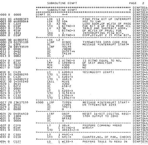
4. 1. DINPT
The execution of SUMON always s t a r t s with a call for subroutine
DINPT (cf. p r o g r a m listing SUMON). F i r s t of all the four
con-t r o l words and nine s c a l e r s a r e r e a d in dacon-ta channel operacon-tion
(with external synchronization). Each control or s c a l e r word is
checked for p a r i t y e r r o r s and invalid digits. If an e r r o r is d e
-tected the control and s c a l e r words a r e r e a d again. If after two
repetitions the e r r o r still p e r s i s t s i n t e r r u p t servicing is t e r m i
-nated by e r r o r exit. The corresponding e r r o r m e s s a g e is printed
on the interface t y p e w r i t e r and on the computer t y p e w r i t e r .
If the control and data words a r e c o r r e c t l y r e a d they a r e decoded
in o r d e r to provide DINPT with information about the type of data
to be handled.
12
-4 . 2 . STORE
Subroutine STORE is entered when the operation code is 1 or 3.
Operation code 1:
STORE has to store the c o r r e c t l y t r a n s f e r r e d s p e c t r u m under its
identification number into a disk file which is common to all data
acquisition stations and which can be used by offline and i n t e r a c
-tive data reduction p r o g r a m s ( (3), ( l ) ) .
F i r s t the s p e c t r u m is converted from BCD to double word binary
format. If the operation indicator had been set to 1 (automatic
operation) the total count of the s p e c t r u m a s calculated by the
p r o g r a m is c o m p a r e d to the total count r e a d from s c a l e r 2. In
c a s e of d i s a g r e e m e n t i n t e r r u p t servicing is t e r m i n a t e d by e r r o r
exit.
If the total count check h a s had a positive r e s u l t (or has been
skipped) p r o g r a m STORE t r i e s to write the s p e c t r u m into the
r e s e r v e d common disk file. This action can only be s u c c e s s
-fully completed if enough disk r o o m is available. If this i s not
the c a s e a m e s s a g e is sent to the interface t y p e w r i t e r of the
station which initiated the i n t e r r u p t and i n t e r r u p t servicing is
t e r m i n a t e d without the s p e c t r u m being stored. If enough disk
r o o m is available the s p e c t r u m is stored and the i n t e r r u p t
servicing is finished.
Operation code 3:
S p e c t r a t r a n s f e r r e d to the computer with the s a m e identification
no. a r e summed up. The summing p r o c e d u r e is s t a r t e d with a
s p e c t r u m stored on disk with operation code 1. All s p e c t r a with
the same identification no. sent subsequently to the computer
with the operation code 3 will be added to the f i r s t s p e c t r u m .
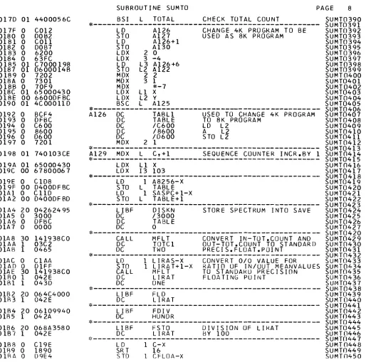
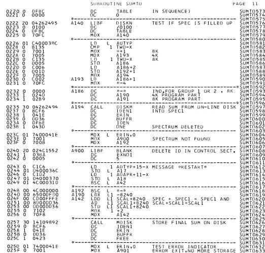
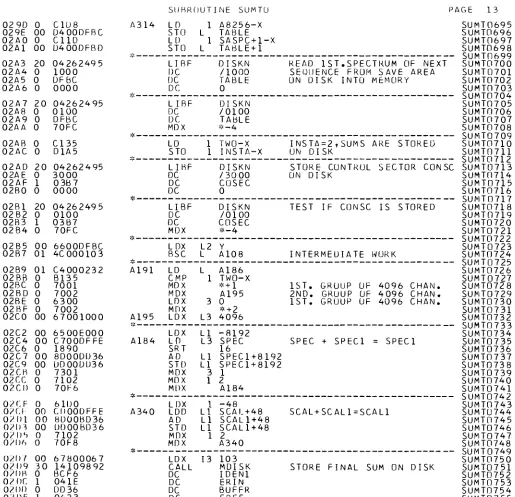
4 . 3 . SUMTO
Subroutine SUMTO is executed after DINPT if the operation code
is 0. In this c a s e the o p e r a t o r of the data acquisition station
wants to m e a s u r e a s e r i e s of s p e c t r a with automatic sample
chan-ger operation. In this mode of operation s p e c t r a (4096 channels)
belonging to different sample changer positions a r e t r a n s f e r r e d
to the computer and added to the s u m s of previously t r a n s f e r r e d
13
-Sample changer Number of Run type identification
sequence indicator run types by 2nd exper. no.
2 2 0, 1
3 3 0 , 1 , 2
4 4 0 , 1 , 2 , 3
Spectra belonging to different sample changer positions a r e
identified by 0, 1, 2, 3 in the position of the 2nd experiment no.
of the identification n u m b e r .
When SUMTO is called the f i r s t t i m e for a new identification
number disk r o o m is r e s e r v e d in the file SPZNE(3) for as many
r u n s as t h e r e a r e run types in the sample changer sequence
specified. In addition to this a save a r e a is r e s e r v e d in SPZNE
for each run type (see below .' ).
Control information which c h a r a c t e r i z e s the e x p e r i m e n t under
consideration (identification no. , sample changer sequence
indicator, e t c . ) and which is n e c e s s a r y for the p r o c e d u r e of
summing up all s p e c t r a of the s a m e run type a r e stored in
control sector CONSC (cf. 4. 6. ) on disk.
During each execution of SUMTO it is checked if the run type
under consideration belongs to the specified sample changer
sequence or not. If not the s p e c t r u m is s u p p r e s s e d . SUMTO
also checks if the different run types cf a sample changer s e
quence follow each other c o r r e c t l y , e. g. run type 1 m a y not
d i r e c t l y be followed by run type 3. Spectra of the same run type
m a y follow each other. This can occur when the count capacity
of an a n a l y s e r channel is exhausted before the p r e s e t count
for the total s p e c t r u m has been reached. If the run types a r e
out of sequence they a r e s u p p r e s s e d until the sample changer
s t a r t s again with run type 0. During one sample changer s e
quence each c o r r e c t l y t r a n s f e r r e d s p e c t r u m is stored in a
t e m p o r a r y a r e a on disk.
14
-E v e r y fifth c o r r e c t sequence the s u m s for the different run types
a r e s t o r e d twice: in the n o r m a l way a s after each c o r r e c t sequence
and into a save a r e a . Therefore only up to five sequences m a y be
lost if something goes wrong in a summing p r o c e d u r e . The
iden-tification n u m b e r s of the sums in the save a r e a a r e defined by the
computer by adding 50 to the s e r i a l no. in the identification no.
which has been specified by the o p e r a t o r of the interface unit.
4 . 4 . SUMON E r r o r M e s s a g e s
All e r r o r m e s s a g e s of SUMON which m a y be printed on an interface
t y p e w r i t e r a r e listed below. Most of t h e s e m e s s a g e s a r e also printed
on the IBM 1816 in the computer room (cf. p r o g r a m listings ! ).
A. DINPT and STORE
1) e r r o r word. . : Call e l e c t r o n i c s engineer !
2) block n u m b e r s i n c o r r e c t : The total n u m b e r of blocks to be
t r a n s f e r r e d and the no. of the a n a l y s e r block to s t a r t with
d i s a g r e e .
3) no. of blocks g r e a t e r 16: S p e c t r a with m o r e than 16 blocks
cannot be t r a n s f e r r e d .
4) check i n t e r r u p t assignment: The group no. of the s p e c t r u m to be
t r a n s f e r r e d m u s t be equal to the i n t e r r u p t a s s i g n m e n t no.
Analyser I n t e r r u p t A s s i g n m e n t No.
TMC-Linac 01
TMC-VdG 10
INTERTECHN. I , Linac 02
INTERTECHN. II, Linac 09
INTERTECHN. Ill, Linac 04
SKIP, radioisotopes group 12
5) block. . cannot be a d d r e s s e d : Call e l e c t r o n i c s engineer .'
6) length of block. . i n c o r r e c t : Call e l e c t r o n i c s engineer
I
7) word e r r o r block. . , channel. . . : Call e l e c t r o n i c s engineer !
8) control word 4 and p r e s e t count d i s a g r e e : This check is only
made for automatic sample changer operation. Call e l e c t r o n i c s
engineer .'
9) i n c o r r e c t automatic type: Call e l e c t r o n i c s engineer J
10) i n c o r r e c t sample changer indicator: This check is only m a d e
for automatic sample changer operation. Call e l e c t r o n i c s engineer.'
11) Check op. code: O P . CODE and position of level switch do not
a g r e e or OP. CODE is i n c o r r e c t
{l).
15
-13) no storage for this s p e c t r u m : In this c a s e a s p e c t r u m with
l e s s overflow channels (= channels with a count higher than
65535) or with l e s s blocks can still be stored. Use OP. CODE
18 to get information about available disk r o o m ( l ) .
14) total count difference g r e a t e r 20: This check is m a d e by
STORE if automatic operation is specified. Call e l e c t r o n i c s
engineer .'
15) i n c o r r e c t automatic type: F o r the t r a n s f e r of s p e c t r a the
automatic type m u s t be 1. F o r change of automatic type
call electronics engineer
I
B. SUMTO
16) i n c o r r e c t s e r i a l no. : The l a s t two digits of the identification
no. m u s t be between 0 and 49.
17) total count difference g r e a t e r 100: The total count for a
s p e c t r u m as given in SCALER 1 does not a g r e e with the
total count calculated by the computer. The sequence in
which this s p e c t r u m o c c u r s is s u p p r e s s e d .
18) no disk storage for s u m s : The e x p e r i m e n t cannot be s t a r t e d
because t h e r e is not enough disk room available.
Delete s p e c t r a which a r e no m o r e used.
19) i n c o r r e c t in/out ratio, total no. of s u p p r e s s e d seq. = . . . . ,
total no. of c o r r e c t seq. = . . . . : A sequence with i n c o r r e c t
IN/OUT ratio is s u p p r e s s e d .
20) i n c o r r e c t sample changer s t a r t : The run type under c o n s i
-deration is s u p p r e s s e d . Each new sequence m u s t s t a r t with
run type 0.
21) run type i n c o r r e c t : The run type of this s p e c t r u m does not
belong to those specified for this e x p e r i m e n t .
22) sample changer e r r o r : The run types do not follow each
.other c o r r e c t l y . The sequence in which this e r r o r o c c u r s
is s u p p r e s s e d .
23) no summing for small s p e c t r a : Check if block n u m b e r s a r e
c o r r e c t .
24) r e s t a r t : You a r e using the identification number of the
preceding experiment whilst the corresponding sums on
disk have a l r e a d y been deleted. Use other identification no.
2 5) no m o r e storage for s u m s : The experiment is stopped by the
16
26) no m o r e storage to save s u m s : The e x p e r i m e n t is stopped by
the computer because the disk save a r e a for the sums is too
s m a l l . Delete s p e c t r a which a r e no m o r e used and continue
with s a m e identification no.
4. 5. Subroutine Set of SUMON
The u s e r written subroutines of the t h r e e m a i n subroutines
DINPT, STORE, and SUMTO of p r o g r a m SUMON (except those
a l r e a d y published elsewhere) a r e d e s c r i b e d below. They m a y
only be used in ASSEMBLER language calling p r o g r a m m e s .
Subroutines published e l s e w h e r e :
DISKM, MDISK, M F L T , SPSRC, SUMT (3)
BLANK, CHIF, MOVE, MOVEI (4)
Subroutines d e s c r i b e d h e r e : BIDEC
DECBY
DEBY8
FORMT
MOVEF
P E R
RESET
TICON
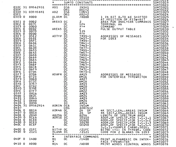
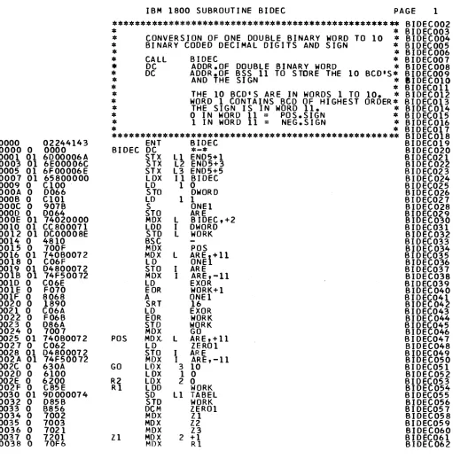
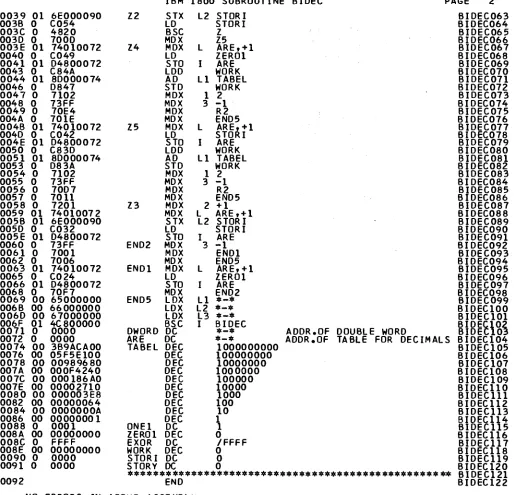
BIDEC
Entry points with calling sequence:
CALL BIDEC
DC ADDR1
DC ADDR2
Subroutines called by BIDEC: None
Core locations used: 150 (96 hexadec. )
Description:
BIDEC converts a double binary word at a d d r e s s ADDR1 to
10 binary coded decimals and a sign which a r e stored into
11 m e m o r y locations starting at a d d r e s s ADDR2. The 10
BDC's a r e in words 1 to 10, word 1 containing the BCD of
highest o r d e r . The sign is stored in word 1 1 : 0 = positive,
17
-DECBY
E n t r y point with calling sequence:
CALL DECBY
DC ADDR
DC N
Subroutines called by DECBY: None
Core locations used: 214 (D6 hexadec. )
Description:
DECBY converts a table of N double words in a n a l y s e r format
(cf. 3) to double word binary n u m b e r s . ADDR is the a d d r e s s
of t h e first double word in the t a b l e .
DEBY8
E n t r y point with calling sequence:
CALL DECBY
DC ADDR
DC N
Subroutines called by DEB Y 8: None
Core locations used: 84 (54 hexadec. )
Description:
DEBY8 converts a table of N half-words in a n a l y s e r format (3)
to 16 bit binary n u m b e r s . ADDR is the a d d r e s s of the first
half-word in the table. Each half-half-word contains the decimal digits
18
-FORMT
E n t r y point with calling sequence:
CALL FORMT
DC ADDR
DC N
Subroutines called by FORMT: BIDEC
Core locations used: 64 (40 hexadec. )
Description:
FORMT converts a table of N double word binary n u m b e r s to
a n a l y s e r format (cf. 3). ADDR is the a d d r e s s of the first
double word in the table.
MOVEF
E n t r y point with calling sequence:
CALL M O V E F
DC ORG
DC DEST
DC N
Subroutines called by MOVEF: none
Core locations used: 32 (20 hexadec. )
Description:
19
-P E R
E n t r y point with calling sequence:
CALL PER
DC ADDR
DC N
DC I
DC NO
CALL+5 ERROR EXIT
CALL+6 NO-ERROR EXIT
Subroutines called by P E R : None
Core locations used: 122 (6E hexadec. )
Description:
P E R checks a table of N double words in a n a l y s e r format (cf. 3)
for p a r i t y e r r o r s and invalid digits. ADDR is the a d d r e s s of the
first word in the table. I is 0 for a p a r i t y e r r o r and 1 for an
in-valid digit. NO is the number of the e r r o n e o u s double word in
the table. P E R b r a n c h e s to CALL+5 if an e r r o r i s found and to
CALL+6 if no e r r o r has been detected.
RESET
E n t r y point with calling sequence:
CALL RESET
DC ADDR1
DC ADDR2
Subroutines called by RESET: DAOP (TSX System)
TYPEN (TSX System)
Core locations used: 52 (34 hexadec. )
Description:
20
-ADDRl is the a d d r e s s of the number of the data acquisition
station (interface unit) involved in the data channel operation.
This number m u s t be in IBM 1053 t y p e w r i t e r code.
TICON
E n t r y point with calling sequence:
CALL TICON
DC ADDR
Subroutined called by TICON: BINDC (TSX System)
CLOCK (TSX System)
HOLPR (TSX System)
Core locations used: 18 (22 hexadec. )
Description:
TICON converts the d a y - t i m e to IBM 1053 t y p e w r i t e r code
in the format XX. XXX hours and s t o r e s the converted t i m e
into t h r e e m e m o r y locations starting at ADDR.
4. 6. Disk F i l e s for SUMON
The disk files used by DINPT, STORE, and SUMTO a r e
d e s c r i b e d h e r e . F o r the disk files belonging to the s u b
routines of DINPT, STORE, and SUMTO the r e a d e r is r e
-f e r r e d to the descriptions o-f the subroutines.
CONDI (1 sector)
CONDI is a control sector for DINPT and STORE. It contains
the identification number of the s p e c t r u m being handled by
DINPT or STORE and status information about the p r o g r e s s
of work done by these p r o g r a m s . In c a s e of a computer failure
during the execution of DINPT o r STORE CONDI d e l i v e r s
21
C ONS C (1 sector)
CONSC is used by SUMTO to t r a n s f e r information from one
i n t e r r u p t to the next one during automatic sample changer
operation. CONSC contains the identification n u m b e r s for
the s p e c t r a of the sample changer sequence, the sample chan
ger sequence indicator, the total counts for the s p e c t r a of one
sequence, indicators for the control of the sample changer,
counters for the number of c o r r e c t and the n u m b e r of s u p p r e s
sed sequences, the n u m b e r s for the IN/OUT check, a d d r e s s e s
for i n t e r m e d i a t e disk storage of s p e c t r a , etc. F o r each data
acquisition station using SUMTO a disk file of this type (with
a different name) is needed.
INSUM (104 s e c t o r s )
INSUM is used by SUMTO as i n t e r m e d i a t e storage for the s p e c t r a
of one sample changer sequence (maximum 4 run types 0, 1, 2, 3).
This storage is n e c e s s a r y b e c a u s e the single s p e c t r a can only
be added to the s u m s of all previous s p e c t r a of the s a m e run
type when a sequence is t e r m i n a t e d . It is only then when it can
be checked if all s p e c t r a of a sequence a r e c o r r e c t . F o r each
data acquisition station using SUMTO a disk file of this type
(with a different name) is needed.
SAVS Ρ (26 s e c t o r s )
SAVSP is used by SUMTO as i n t e r m e d i a t e storage for the first
run type of a sample changer sequence during the t i m e the
s p e c t r a of the preceding sequence a r e added to the c o r r e s
ponding sums on disk.
5. Test and Utility P r o g r a m s
5. 1. On-Line Interface Test P r o g r a m s
22
-The m a i n t e s t possibilities a r e :
- Read control w o r d s , r e a d - w r i t e operation for s c a l e r s and
a n a l y s e r channels with any wanted bit combination contained
in a p a t t e r n (cf. 5. 1. 7. ).
- A continuous execution of t e s t s to allow convenient on-line
control of the interface h a r d w a r e by the electronics e n g i n e e r s .
- Check interface t y p e w r i t e r , print out loaded p a t t e r n or w r i t e
p a t t e r n blocks into m u l t i - c h a n n e l a n a l y s e r m e m o r y .
5. 1. 1. Interface Typewriter Test - OP.CODE 91 (PRALl)
All c h a r a c t e r s in use a r e printed on the interface t y p e w r i t e r .
A - Z, 0 - 9, / . , + SPACE - * = and line feed, shift to black
and shift to red.
h 1Ά·-
_R ead _W xit e W ORD _T e s t
_-_9^Ç9P_E_9_2_ _(WORD2_)_
This t e s t c o m p r i s e s four steps
Step 1: The control word 1 (Fig. 3) and all s c a l e r s in u s e (up
to flag bit) a r e r e a d in d i r e c t p r o g r a m control and c o m
-p a r e d to the -p a t t e r n stored on disk (cf. 5. 1. 7. ). The u s e r
h a s t h e r e f o r e to introduce the p a t t e r n values in c o r r e c t
sequence in control word 1 and in the s c a l e r s . In c a s e the
r e a d w o r d s and the p a t t e r n words d i s a g r e e , both words
a r e printed (see e r r o r m e s s a g e s ) .
Step 2: All p a t t e r n words a r e written into each s c a l e r and r e a d
back in d i r e c t p r o g r a m control. Written and r e a d words
a r e c o m p a r e d and printed if an e r r o r is detected.
Step 3: Identical to step 2 except that t r a n s f e r s a r e done in
data channel operation with e x t e r n a l synchronization.
F i n a l l y the command PRINT WORDS is delivered.
A m e s s a g e i s provided at the beginning and at the end of the test.
The t e s t is i n t e r r u p t e d if m o r e than 5 e r r o r s a r e detected.
E r r o r m e s s a g e s :
S T E P 1 - 3
WRONG WORD No. (0 - 9)
PW = / C H E X / C H E X ( P a t t e r n word)
IW = / C H E X / C H E X (Interface word)
CHEX a r e 4 hexadecimal digits (Fig. 3)
23
5. 1. 3. T r a n s f e r of P a t t e r n Blocks - O P . CODE 93 (WBLC3)
The 16 (10)* double word p a t t e r n is used 16 (10) t i m e s to form
a block of 2 56 (100)* channels. All 16 a n a l y s e r blocks a r e fed
with the s a m e p a t t e r n block.
w
SKIPP a n a l y s e r with 16 blocks of 100 channels
5. 1.4.__Print Loaded P a t t e r n - O P . CODE 94 (PATP4)
The p a t t e r n actually stored on disk is printed out on the i n t e r
-face t y p e w r i t e r .
5. 1. 5. Analyser Block Test - O P . CODE 95 (BLOC5)
This t e s t c o m p r i s e s t h r e e s t e p s .
Step 1: The 16 possible block a d d r e s s e s a r e delivered c o n s e
-cutively and the control word 2 block a d d r e s s
indica-tion is checked. In c a s e of d i s a g r e e m e n t the a d d r e s s e d
and the r e a d block n u m b e r s a r e printed.
Step 2: A p a t t e r n block (cf. 5. 1, 3. ) is written into each a n a l y s e r
block, r e a d back and c o m p a r e d . The flag bit on the second
word of the l a s t double word in each block is also checked.
Step 3: The a n a l y s e r is r e s e t from block 3 to block 12 with two
consecutive block r e s e t c o m m a n d s .
The beginning and the end of the t e s t a r e indicated on the p r i n t e r .
The t e s t is i n t e r r u p t e d if m o r e than 5 e r r o r s a r e detected.
E r r o r m e s s a g e s :
Block a d d r e s s i n g e r r o r :
BLOCK No. 0 - 15
BLOCK No. 0 - 1 5 (in red)
- F l a g bit e r r o r :
BLOCK No. 0 - 15
INCORRECT BLOCK LENGTH
- Analyser channel e r r o r :
BLOCK No. 0 - 1 5
WRONG WORD NR 0 - 2 5 6 (100)
PW = / C H E X / C H E X
IW = / C H E X / C H E X
24
5. 1. 6. Continuous Block Test - O P . CODE 96 (COBA6)
No e r r o r m e s s a g e s a r e provided in this routine but a d e s i r e d
t e s t cycle is executed continuously. The u s e r has s e v e r a l t e s t
options to be selected with the group no. contained in control
word 1.
Step 1: The control word 1 is r e a d and a t e s t block of 2 56
(100) channels is formed, each channel containing
5 (6) decimal digits of the control word 1 as channel
count.
Step 2 : - Group no. < 10:
The t e s t block is t r a n s m i t t e d to the 16 a n a l y s e r blocks
and the p r o g r a m continues with step 3.
- 10 < group no. < 20:
All 16 a n a l y s e r blocks a r e r e a d into the computer
and the p r o g r a m p r o c e e d s to step 3.
- Group no. > 20:
The p r o g r a m goes i m m e d i a t e l y to step 3.
Group no. and 1. experiment no. = 0 : all blocks of
the a n a l y s e r a r e r e s e t to z e r o .
Step 3: If the group no. is negative, the t e s t is t e r m i n a t e d
and the i n t e r r u p t level is given free, otherwise the
p r o g r a m r e t u r n s to step 1.
5. 1. 7. P r o g r a m to Load the Test P a t t e r n on Disk (PATRN)
The t e s t p a t t e r n is s t o r e d on disk by m e a n s of the n o n - p r o c e s s
p r o g r a m PATRN. The 6 decimal digits of the 16 p a t t e r n double
words have to be punched on 16 c a r d s in the following f o r m a t .
FIRST WORD
10 11 12
0-9 0 - 9 0-9
SECOND WORD
20 21 22
0-9 0-9 0-9
WORD No
79 80
1 - 16
CARD COLUMN
The control bits (flag bit, p a r i t y bit, f i r s t or second word bits)
a r e added by the loading p r o g r a m PATRN before the values a r e
s t o r e d on disk.
5.2. Off-Line Interface Test P r o g r a m s
25
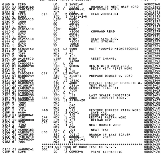
5.2. 1. Continuous Word Test (WORDT)
The four control and the nine s c a l e r double words a r e read in
data channel operation with external synchronization. The f i r s t
data block is m e m o r i z e d and printed. Any subsequently r e a d
data block differing from the f i r s t block is printed on the 1443
p r i n t e r . After 16 e r r o r s have been detected, the p r o g r a m
continuous to read without printing.
The number of the station to be t e s t e d is introduced via the
DATA SWITCHES.
The computer can only get information from a station which
is on-line i. e. the u s e r m u s t first r e q u e s t an i n t e r r u p t on
LEVEL II with OP. CODE 99 : The i n t e r r u p t level is immediately
left without giving an end-of-interrupt command to the station,
leaving the unit on-line.
The i n t e r r u p t p r o g r a m ENDIN (5. 3. 2. ) is used to set the unit
off-line after the t e s t .
5 . 2 . 2 . F r o n t - E n d Adapter Test (FEAT)
The front-end adapter, which links the interface units to the
computer, s e p e r a t e s the different ground potentials and
enables two-way data exchange. The digital output r e g i s t e r
DOR2 (cf. 2) is switched via the front-end adapter to the
digital input r e g i s t e r DIR. The p r o g r a m w r i t e s into DOR2
special bit configurations in d i r e c t p r o g r a m control, r e a d s
back the DIR and c o m p a r e s the two r e g i s t e r s . Both
configu-r a t i o n s a configu-r e pconfigu-rinted on the s y s t e m p configu-r i n t e configu-r if any d i s c configu-r e p a n c y
is found. All DATA SWITCHES i n OFF position s u p p r e s s the
printing.
The t e s t stops if 16 e r r o r s have been printed. To continue
the test, p r e s s CONSOLE START.
5. 3. General Utility P r o g r a m s
The computer o p e r a t o r can prevent or enable any interface unit
to r e q u e s t i n t e r r u p t s or can turn "off-line" an interface unit which,
due to e r r o n e o u s operation or due to t e s t s ( 5 . 2 . 1. ) did not r e
26
-5. 3. 1. P r o g r a m to Enable or Disable Interface Stations (IFOP)
P r e s s CONSOLE INTERRUPT with SENSE SWITCH 1 ON .
To enable interface units 1 - 1 5 , set ON the corresponding
DATA SWITCHES. All OFFDATA SWITCHES m a s k the c o r
-responding u n i t s . The c u r r e n t status of the " m a s k e d - u n m a s k e d "
units is printed on the s y s t e m p r i n t e r .
5 . 3 . 2 . Manual End-of-Interrupt Command (ENDIN)
P r e s s CONSOLE INTERRUPT with SENSE SWITCH 0 ON and
1 ON. Set ON the DATA SWITCH corresponding to the i n t e r
-face unit to be a d d r e s s e d (1 - 15).
A m e s s a g e on the s y s t e m p r i n t e r specifies the executed o p e r a
-tion and the unit n u m b e r .
Acknowledgements
27
-6. References
(1) Horstmann, H., IBM 1800 P r o g r a m s for Data Processing
at the Accelerators of the Central Bureau for Nuclear
Measurements, P a r t 3: P r o g r a m s for Interactive Data
Reduction, EUR report in p r e s s . No. 44O4 e/3
(2) Colling, F . , De Keyser, A . , Horstmann, Η. , Multi
parameter Data Acquisition with a Satellite Computer,
IFIP Congress 71, Ljubljana.
(3) Schmid, H., Horstmann, H., Ciaessens, H., IBM 1800
P r o g r a m s for Data Processing at the Accelerators of the
Central Bureau for Nuclear Measurements, P a r t 2:
Off-Line P r o g r a m s for Data Handling and Reduction,
EUR 4404 e, 1969.
(4) Schmid, H., Ciaessens, H., IBM 1800 Utility P r o g r a m s
for Magnetic Tapes and T e l e - P r o c e s s i n g Input/Output,
EUR 4263 e, 1969.
(5) Schmid, H. , An IBM 1800 P r o g r a m Package for On-Line
and Off-Line Operation of a CALCOMP Digital Incremental
Plotter, EUR 4225 e, 1969.
(6) Nastri, G., Cervini, C., The Three-Dimensional
Plotting Program TRICE, EUR 4484 e, 1970.
(7) De Keyser, A. , de Jonge, S. , van der Veen, T.,
ter Meer, P. , Analyser Computer Interface, International
Symposium on Nuclear Electronics, Vol. 2 (SFER, P a r i s ,
1968), p. 135.
LINEAR ACCELERATOR
28
«OM CHANNEL ANALYSER I
«096 CHANNEL ANALYSER 2
4096 CHANNEL ANALYSER 3
4096 CHANNEL ANALYSER 4
4096 CHANNEL ANALYSER S
COMPUTER OA 18/30 1.2 μ M e , 16 K
VAN
4096 CHANNEL ANALYSER 6
RA
1600 CHANNEL ANALYSER
DE ORA
DIOISOT
INTERFACE TYPE A
INTERFACE TYPE A
INTERFACE TYPE A
INTERFACE TYPE A
INTERFACE TYPE A
INTERFACE TYPE Β
AF F
INTERFACE TYPE A
3PES
INTERFACE TYPE A
oc UI H·
OL
<
α
<
IBM 1600
32 Κ
* χ 1810
3x2401-1
1442-7
1 4 4 3 - 2
1816
CALCOMP
IBM 2780 TERMINAL GEEL
10
III
_l
i
e
in •e
III
ζ 3 UI ζ
o
ζ α. UI -J Ui
1-IBM 360/65 1SPRA
768 Κ 2x2314 5x2401 2301
29
0
F Ρ 0 0
0
F Ρ 0 1
BCD1
BCD 2
FIRST WORD
BCDA
BCD5
15
BCD3
15
BCD6
SECOND WORD
F = FLAG BIT
Ρ = ODD PARITY OF 16 BIT WORD
BCD1-BCD6 = BINARY CODED DECIMALS
Fig. 2a General data format for digital input
7 8
11 12
15
OPERATION CODE
W OR Β
S
W = WORD ADDRESS
Β = BLOCK ADDRESS
S = STATION ADDRESS
OENERAL FORMAT
Fl Ρ 0 0 BCD1 BC02 BC03
ANALYSER CHANNEL OR SCALER WORD
Fl Ρ 0 0 η» 10* β3
CONTROL WORD 1 (ADDRESS 0 I
Fl Ρ 0 0 Group number
»' Ι ίο"
1. experiment no. ufi
CONTROL WORD 2 (ADDRESS F)
Fl Ρ 0 0 Net uMd Operatt
».
m code
10°
CONTROL WORD 3 (ADDRESS A )
Ρ 0 0
Number of block« in the spectrum
10'
¡
»°
Na of first block In the spectrum
»3
CONTROL WORD 4 (ADDRESS B)
Ρ 0 0 Monitor count
» 5 | K>*
-F2 Ρ 0 1 BCD* BCDS BCD8
F2 Ρ 0 1 ttJ
»'
IO»Ρ
o
1 2. experiment na 10°Serial number
io'
J
« °
F t , F 2 : F l a g b l t i
P: ODD parity of 16 bit word BCDl-BCD«: Binary coded decimals
F 1 « 1 : Scaler value to be multiplied by M F2 » 1 : Last scaler or last
channel in analyser
Fl «1: Read destructive
Ρ 0 1 Address of analyser block
8 ' J β "
Sample changer sequence indicator ΙΟ»
Fi » l: Automatic operation Fl ■ 0: Manual operation
Ρ 0 1 Number of first block in the spectrum
W2 i W1 « 0
Ρ 0 1 Monitor count
Cd O
31
I n s t r u c t i o n Code
1 4 X S
2 2 W S
2 3 W S
2 4 W S
3 2 Β S
3 4 Β S
3 0 Β S
4 2 Χ S
8 0 Χ S
A 0 Χ S
Β 0 X S
E 8 Χ S
F 8 X S
F u n c t i o n
PRIKT A L P H A M E R I C
READ F I R S T 16 BITS O F WORD W
READ SECOND 16 BITS O F WORD W
WRITE WORD W
READ ANALYSER BLOCK Β
WRITE ANALYSER BLOCK Β
CLEAR ANALYSER BLOCK Β
READ WORDS
CLEAR SCALERS
P R I N T WORDS
END O F I N T E R R U P T
DISABLE STATION S
E N A B L E STATION S
S = s t a t i o n a d d r e s s
W = w o r d a d d r e s s
Β = block a d d r e s s
X = not u s e d
0000 30 0002 0 0003 0005 0006 0008
01 0 3 0 30
000Δ
0 4 2 5 5 5 Ε 3 0 0 0 0 7 4 0 0 0 0 0 2 7 0 0 2 2 2 9 1 4 8 D 6 2 2 8 D 6 6 4 5
0 0 0 0
IBM 1 8 0 0 PROGRAM SUMON PAGE 1
* * * * * * * * * * * * * * * * * * * * * * * * * * * * * * * * * * * * * * * * * * * * * * * * * * *
■* MAIN PROGRAM SUMON *
* * * * * * * * * * * * * * * * * * * * * * * * * * * * * * * * * * * * * * * * * * * * * * * * * * * START CALL
DC
MDX
MDX
CALL CALL
DINPT
Λ>rrl jit
START+2,0 A l
SUMTO STORE
D I G I T A L INPUT OF
OPERATION CODE SPECTRUM
AUTOMATIC SAMPLE CHANGER
A I CALL STORE STORE SPECTRUM
* * * * * * * * * * * * * * * * * * * * * * * * * * * * * * * * * * * * * * * * * * * * * * * * * * *
END START
SUM0N002 SUM0N003 SUM0N004 SUM0N005 SUM0N006 SUM0N007 SUM0N008 SUMON009 SUM0N010 SUM0N011 SUM0N012
NO ERRORS IN ABOVE ASSEMBLY. SUMON
DUP FUNCTION COMPLETED / / DUP
*STORECIM I UA 1 SUMON SUMON
*LOCALDINPT,SUMTO »STORE *CCEND
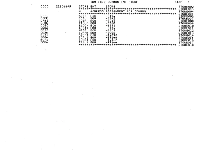
0000
DFFE DFCE DFBE DFBC DDBC DDBA DD9E DD36
0 4 2 5 5 5 E 3 ENT DINPT
* * * * * * * * * * * * * * * * * * * * * * * * * * * *
*
A^S^
E.§
S.
*? *Tf* T· 'f f 't* "fi *l- Ύ· Τ V f 'f· SPEC EOU SCAL EOU IDEN EOU TABLE EOU BLOCK EOU AREAI EOU MESS EOU BUFFR^ EOU^
¥ τ· 'ή »i W 'íV ■? ι· ι· ι* τ
ASSIGNMENT FUR
* * * * * * * * * * * * * * *
- 8 1 9 4 - 8 2 4 2 - 8 2 5 8 - 8 2 6 0 - 8 7 7 2 - 8 7 7 4 - 8 8 0 2 - 8 9 0 6
* * * * * * * * * * * * * * *
IBM 1 8 0 0 SUBROUTINE DINPT PAGE 1
D I N P T 0 0 2 * * * * * * * * * * * * * * * * * * * * * * # D I N P T 0 0 3
COMMON * D I N P T 0 0 4
ι : * * * * * * * * * * * * * * * * * * * * * * ο I NPT005 D I N P T 0 0 6 D I N P T 0 0 7 D I N P T 0 0 8 D I N P T 0 0 9 D I N P T 0 1 0 D I N P T 0 1 1 D I N P T 0 1 2 D I N P T 0 1 3 £ * ν ν * * * * * * * * * * * * * * * * * * * Qj NPT014
SUBROUTINE DINPT
PAGE
OOOO 0 0000
0 0 0 1 0 0 0 3 0 0 0 5 0006 0 0 0 7 0008 0 0 0 9 OOOA
OOOB OOOD OOOE OOOF 0010 0 0 1 1 0012 0 0 1 3
0 0 1 4 0015 0 0 1 6 0017
0018 0 0 1 9 001B 001C 001E 0 0 2 0 0 0 2 1 0 0 2 2 0023 0 0 2 4 0025 0 0 2 6
0 0 2 7 0028 0 0 2 9 002Δ
002B 002C 0 0 2 0 002E
0 0 2 F 0 0 3 0 0 0 3 1
0 0 3 2 0033
01 00 0 0 0 0 0 0
00 2 0 1 20 0
1 1 0
0 0 0 0
0 0 1 0 0 1 30 1 1 0 0 0 0 0
20 0
1 0
20 0 1 0
0 0 0
0 0
6 5 0 0 0 3 E 9 6 6 8 0 0 0 6 8 C228 D1BF C226 91BF 1 8 0 1 D1BF
6600DFBC 0 2 2 5 5 1 0 3 03FE 0 8 5 9 3 5 0 9 0 0 0 0 0 4 0 2 0 4 2 2 0 0 0 2
C1BF B122 7 0 1 0 700F
C129 D40002B5 C12A D 4 0 0 0 2 E 2 1 4 5 A 5 1 4 0 0 4 1 4 0 2 F 2 0 0 0 6 C 1 3 1 D1FF C132 U10B
2 3 A 1 7 1 5 5 2 0 0 1 0 4 1 0 0 0 0 0
0 4 0 5 6 5 C 0 1 0 0 0 0 3 B 4 0 0 0 0
C1FA 81BF D1D1
C10D D U O
0034 O C127
*************************************************** DINPT016
*
SUBROUTINE DINPT
* DINPT017
*************************************************** DINPT018
DINPT DC
**
DINPT019
*
DINPT020
LDX LI X
FIND PISW BIT OF INTERRUPT DINPT021
LDX 12 104
XR2 TO LWA
DINPT022
LD
X2 40
LOAD ADDR.OF WC/SA OF PROG DINPT023
STO
1 BITNOX
FOR BIT 0 OF PISW FROM ICL DINPT024
LD
X2 38
TABLE AND SUBTRACT ADDR.
DINPT025
S
1 BITNOX
OF WC/SA OF PRUG. FOR
DINPT026
SRA
1
INTERRUPTING PISW BIT.
DINPT027
STO
1 BITNOX
DIFF.DIV.BY 2 IS PISW BIT. DINPT028
*
DINPT029
LDX L2 Y
DINPT030
LIBF
BINDC
TYPEWRITER 1053 CODE FOR
DINPT031
DC
OUTPT
MESSAGE «INTERRUPT START* DINPT032
LIBF
HOLPR
DINPT033
DC
/OOOO
DINPT034
DC
OUTPT+4
DINPT035
DC
TM139
DINPT036
DC
2
DINPT037
*
DINPT038
LD
1 BITNOX
IS ΒI TNO EQUAL TO NO.
DINPT039
CMP
1 SPERNX
OF SKIP ANALYSER
DINPT040
MDX
A300
NO
DINPT041
MDX
A300
NO
DINPT042
*
DINPT043
LD
1 A200X
YESÍMODIFY DINPT)
DINPT044
STO L A46+1
DINPT045
LD
1 Δ201Χ
DINPT046
STO L A48+3
DINPT047
CALL
MOVE
DINPT048
DC
Δ202
DINPT049
DC
A582
DINPT050
DC
6
UINPT051
LD
1 A203X
DINPT052
STO
1 BL513X
DINPT053
LO
1 A204X
DINPT054
STO
1 LENGTX
DINPT055
*
.
DINPT056
Δ300 LIBF
TYPEN
MESSAGE «INTERRUPT START* DINPT057
DC
/2001
ON TYPEWRITER 1053
DINPT058
DC
TM11
DINPT059
DC
0
DINPT060
*
DINPT061
LIBF
DAOP
RESET 16BIT DIGITAL REGI DINPT062
DC
/1000
STER OUTPUT TO ZERO
DINPT063
DC
AREA2
DINPT064
DC
O
DINPT065
*
DINPT066
LD
1 B8X
PREPARE COMMANU *READ
DINPT067
A
1 BITNOX
WORDS*
DINPT068
STO
1 AREA3+2X
DINPT069
*
DINPT070
LO 1 MNPCX D I N P T 0 7 1