Improved Performance of Four Switch Three
Phase Brushless DC Motor using Speed-Current
Control Algorithm
P.Rajasekaran
, Assistant Professor, Department of Electrical and ElectronicsEngineering, Velalar College of Engineering and
Technology, Erode-638012 Tamilnadu, India
K.Vanchinathan
Assistant Professor, Department of Electrical and ElectronicsEngineering
Velalar college of Engineering and Technology, Erode-638012, Tamilnadu, India
ABSTRACT
-
A new combined speed and current control algorithm is proposed for four-switch three-phase brushless dc (BLDC) motor drives. A single-current-sensor control strategy is proposed, in which only phase-c current is being measured.Phase-c current is maintained at nearly zero level first, and phase-a and phase-b currents are regulated by speed circle. To improve the controller performance, a single-neuron adaptive proportional–integral (PI) algorithm is adopted to realize the speed regulator. Simulation and results, the proposed strategy shows good self-adapted track ability with low current ripple and strong robustness to the given speed reference model.Keywords-Brushless dc (BLDC) motor, four-switch three-phase inverter, single –neuron proportional –integral controller.
1.
INTRODUCTION
BLDC motor is similar to the permanent magnet synchronous motor in structure and linear torque to current, or speed to voltage similar with DC motor. BLDC motor is variable speed operation, control is easier than other AC machines. It has been the high efficiency, high power density, low noise, and the low maintenance cost due to the removal of the mechanical amateur and brushes [1]-[2]. The performance of such motors has been significantly improved due to great development of power electronics, microelectronics, magnetic performance of magnets, and motion control technology in recent years [3]–[8].
A novel four-switch three-phase BLDC motor drive is proposed to simplify the topological structure of the conventional six-switch inverter. It is an effective try on reducing cost, but the uncontrollable phase current causes unsymmetrical voltage vector, and its waveform is much of distortion from rectangular. The direct current control based on hysteresis avoids this problem, and it senses currents of phases a and b individually by two current sensors and then switches them separately. Therefore, the desired rectangular current waveform is directly obtained [15]. A new speed control method using the acceleration feed forward compensation is proposed to improve the speed response characteristic for a four-switch three-phase BLDC motor [16]. The disturbance torque estimation method is adopted to improve the robustness of the method. It is verified to be economical and efficient in some occasions with light load, such as robot arm, in spite of its average control performance with heavy load [17]. A current control technique is developed to minimize commutation torque for the entire
speed range. Its dynamic and static speed–torque characteristics are proved to be quite good. Intelligent schemes have been introduced into four-switch drives. An adaptive neurofuzzy inference system controller is proposed in [18]. This newly developed design does not require an accurate model of the motor and has a fairly simple structure. Simulation results show better transient and steady-state responses compared with the proportional–integral (PI) controller in the wide speed range. Some work has also been done on a sensorless four-switch BLDC motor drive [19]-[20].Asymmetric PWM scheme for a four-switch three-phase BLDC motor drive to make six commutations and produce four floating phases to detect back electromotive force (back-EMF) [19]. The position information of the rotor can be acquired based on the crossing points of the voltage of controllable phases. In virtual hall sensor signals are made by detecting the zero crossing points of the stator terminal voltages, and there is no need to build a 30◦ phase shift, which is prevalent in most of the sensorless algorithms [20]. The aforementioned research works are all based on two current sensors. To exploit the four-switch BLDC motor drive’s advantage of lower cost, a single-current-sensor control strategy is proposed in this paper. The designed four-switch BLDC motor drive shows satisfying performance despite the reduction of current sensor. In Section II, variation of phase-c current influences another phase currents is analyzed, and the four-switch control strategy based on is proposed. Section III introduces a single-neuron adaptive PI algorithm to the speed regulator to improve control performance and demonstrates implementation of the control system in detail. Finally, simulation result is given in Section IV.
2.
ANALYSIS
OF
THREE
PHASE
BLDC
MOTOR
DRIVE
The analysis is based on the following assumption and BLDC motor model of Fig. 1 for simplification:
1) The motor is not saturated.
2) Stator resistances of all the windings are equal and self and mutual inductances are constant.
3) Power semiconductor devices in the inverter are ideal. 4) Iron losses are negligible.
Where , and are motor phase voltage and is natural voltage of the BLDC motor.
The electromagnetic torque is expressed as
[image:2.595.50.285.69.445.2]Where , and are Phase back EMF, , and are Phase current and angular velocity.
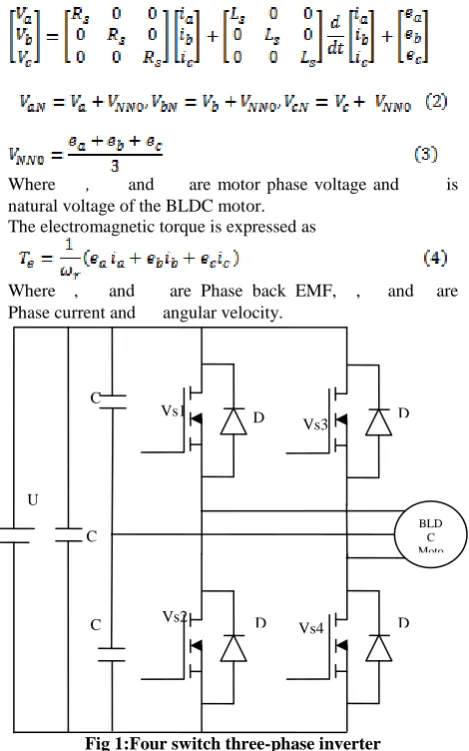
Fig 1:Four switch three-phase inverter
As shown in Fig. 1, two common capacitors, instead of a pair of bridges, are used, and phase c is out of control because it is connected to the midpoint of the series capacitors. A conventional PWM scheme for the six-switch inverter is used for the four-switch inverter topology of the BLDC motor drive. Whole working process of the BLDC motor is divided into six modes, as shown in Table 1.
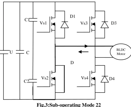
The BLDC motor needs quasi-square current waveforms, which are synchronized with the back-EMF to generate constant output torque and have 120°conducting and 60° non-conducting regions. Also, at every instant, only two phases are conductive, and the other phase is inactive. Phase c involves four modes, including modes 2, 3, 5, and 6.Only one switch should work in the four modes. Taking mode 2 for instance, switches VS1 and diode D2 work to conduct current in this mode. Mode 2 is divided into modes 21 and 22, as shown in Fig. 2 and 3. Switch VS1 turns on, while is less than current threshold I*.
[image:2.595.308.543.86.580.2]The current flows through only two phases, increases and = 0. Then, is controlled indirectly. While − goes beyond I*, switch VS1 turns off, and diode D2 conducts to make and − drop. In this way, and are regulated to vary near the reference value. As far as the situation of modes 1 and 4 is concerned phases a and b have current flowing through, and should be zero.
Table 1.Working mode of the four-switch three phase BLDC motor
Mode Hall values
Working Phase
Current restraint
Conductin g devices
Mode
1 101 +a,-b
Ia=I*,ib
=-I* VS1,VS4
Mode
2 100 +a,-c Ia=I* VS1
Mode
3 110 +b,-c Ib=I* VS3
Mode
4 010 +b,-a
Ib=I*,ia
=-I* VS2,VS3
Mode
5 011 +c,-a Ia=-I* VS2
Mode
6 001 +c,-b Ib=-I* VS4
Fig 2:Sub-operating Mode 21
To avoid current waveform distortion, appropriate switch signals should be respectively used in different a working mode, which implies that some new control schemes should be developed.
U
C 2 C 2
C 2
Vs1
Vs2
Vs4 D 2 D
1 Vs3
D 3
D 4
BLD C Moto
r
D4 D3 Vs3
Vs4
Vs2 D2
D1 C1
C2
U C BLDC Motor
Fig.3:Sub-operating Mode 22
To avoid current waveform distortion, appropriate switch signals should be respectively used in different a working mode, which implies that some new control schemes should be developed.
The voltage equations for a three BLDC motor can be described as
where represents the terminal phase voltage with respect to power ground, is the rectangular-shaped phase current, is the trapezoidal-shaped back-EMF, is the neutral-point voltage with respect to power ground, and R and L are the resistance and equivalent inductance of the phase windings, respectively. As
(7) can be drawn from (5) and (6)
Considering that
So
Where C represents the value of capacitors of C1 and C2 and U is the dc-link voltage. Equation (7) can be rewritten as follows, in which is the only argument.
Assume that at some instant, -E< <E, where E is the amplitude of the back-EMF. At the instant of t = 0, is assumed to be equal to and ≈ 0. If the value of capacitors is large enough, then and
.Considering the case of as
an example, and can be solved from (5) and respectively
To simplify the result, several variable B, r1 and r2 are declared
The variance ratio of is
The Taylor series of at the instant t=0 can be solved,
and all items that are more than one degree are truncated. Then, the variance of at t=0 is
Mode 1 is taken for instance here to demonstrate the whole working process that is identical in mode 4. Mode 1 is divided into four sub-operating modes. Switches VS1 and VS4 work in mode 11 with ua= U and ub = 0. Diodes D2 and D3 work in mode 12 with ua = 0 and ub= U. Switch VS1 and diode D3 work in mode 13 with ua = U and ub = U. Switch VS4 and diode D2 work in mode 14 with Ua = 0 and Ub= 0. The values of Dic/Dt (t=0) in different sub operating modes are shown in Table 2.
Table 2. Different sub-operating modes
Sup-operating mode
Mode 11 U 0
Mode 12 0 U
Mode 13 U 0
Mode 14 0 U
According to Table 2, the four sub-operating modes have different rules to phase current. In mode 11, and − rise quickly, and varies proportionally with the back-EMF of phase c. In mode 12, and − drop quickly, and changes proportionally with the back-EMF of phase c. Compared with modes 11 and 12, falls much quicker in mode 13 and rises much quicker in mode 14. Thus, mode 1 could be optimized by reasonable combination of four sub-operating modes. First of all, the equation = 0 must be satisfied to keep the system stable as follows. When deviates seriously from zero, modes 13 and 14 works. When remains at zero, modes 11 and 12 works. Because and cannot be detected, a speed loop is used here to decide the duty of PWM signals. The same regulating method is used in mode 4, and asymmetric voltage vectors are eliminated.
3.
IMPLEMENTATION
OF
SINGLE-CURRENT-SENSOR
CONTROL
FOR
FOUR-SWITCH
THREE-PHASE
BLDC
MOTOR
A. Single-Neuron Adaptive PI Controller
Due to its merits such as simple structure, high efficiency, and easy implementation, the PI controller is widely used in most servo applications such as actuation,
D 2 Vs1
D4 D3
BLDC Motor
Vs3
Vs4 Vs2
D1 C1
C2
U C
robotics, machine tools, and so on. However, the conventional PI controller is based on a linear model and suffers from parameter sensitivity and nonlinearity of the BLDC motor. Its accuracy is limited on BLDC motor control. With the development of modern computer technology and control theory, new controllers are designed by not only combining the traditional PI strategy with some intelligent technologies but also adjusting PI controllers’ parameters, so PI controllers’ characteristics are improved greatly. The single neuron adaptive PI controller is one of those controllers. Neuron is the basic computing unit of the brain. It works as accumulative information processing properties. A single-neuron model is proposed based on the fact that the output of the neuron is the weighted sum of all the signals coming to it. The advantage of the single-neuron model is its adaptation ability acquired by adjusting the weigh coefficients. Based on the self-study and adaptive ability of the single neuron, a single-neuron adaptive PI controller has the advantages of simple structure, fast response, good adaptability, and robustness and is consequently chosen as the speed controller in this paper.
The regulating rule of the single-neuron adaptive PI controller can be described as follows.
1. Given the initial weight and learning rate of a single neuron, incremental PI controllers are used here, and the control error is
Where r*(t) is the threshold value at time t and r(t) is the
output of the system at time t.
2. The inputs of the single-neuron adaptive PI controller are
The output of the single-neuron adaptive PI controller is
(24) here is the corresponding weight of , and K is the
learning rate of a neuron, with K>0
4. The weight coefficient of a single neuron are tuned by
[image:4.595.58.488.335.622.2]here and are the learning rates of proportion and integration, respectively. They are set to different values, so different weight coefficients can be tuned.
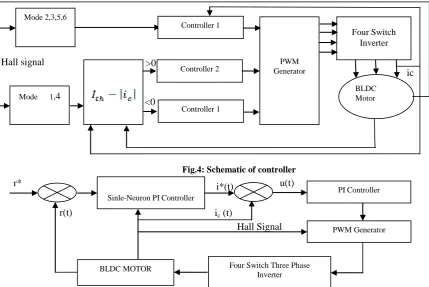
Fig.4: Schematic of controller
Fig 5:Schematic of combined speed and current controller 1
B. Control System
The control system adopts the double-loop structure. The inner current loop maintains the rectangular current waveforms, limits the maximum current, and ensures the stability of the system. The outer speed loop is designed to improve the static and dynamic characteristics of the system. As the system performance is decided by the outer loop, the disturbance caused by the inner loop can be limited by the outer loop. Thus, the current loop adopts the conventional PI controller, and the speed loop adopts the single-neuron adaptive PI controller. Then, the parameter can be regulated
online, and the system is adaptable to different working conditions. The whole system is shown in Fig. 4.
Controller 1: According to Hall signals, controller 1 works when the motor runs at modes 2, 3, 5, and 6. The scheme of controller 1 is shown in Fig. 5.
The single-neuron adaptive PI controller is taken as a speed controller. The speed difference can be represented as
Where r* is the given speed value and r(t) is the measured
speed value at the time t.
Mode 2,3,5,6
Controller 2 Generator PWM
Mode 1,4
Four Switch Inverter
BLDC Motor Controller 1
Controller 1
r(t)
r* i*(t)
ic (t)
Sinle-Neuron PI Controller
Four Switch Three Phase Inverter
PI Controller
PWM Generator
BLDC MOTOR
u(t)
Hall Signal >0
<0
The output of the single-neuron adaptive PI controller I*(t) can be solved by (22)-(27).I*(t) is the threshold value of the current generator. For the safety of the system, I*(t) cannot pass beyond the maximum setting value.
Then ,the input of the current regulator is
An incremental PI controller is used here as a current regulator and its output is
Where T represents the sampling the period and and are the factor of proportion and integration of the current PI regulator respectively. is the duty of PWM signals. Controller 2: In modes 1 and 4, is close to zero. When PI is regarded as equal to zero, and consequently,
. Controller 2 works at this stage, and phases a and b switch synchronously based on the speed loop, just as the traditional six-switch method does, as shown in Fig. 6.
Fig 6: Schematic of speed controller 2
The input of controller 2 is
According to solve (22)-(27),the duty of PWM signal can be solved.
Controller 3: When the motor runs at modes 1 and 4 , controller 3 works, in turn ,instead of controller 2,as shown in fig 7.
[image:5.595.48.278.270.410.2]+
Fig 7: Schematic of current controller 3
When ic > 0 and Ic >ith , the strategy is at the stage of suboperating mode 13, and the magnitude of drops quickly. If = 0, the control flow will quit from controller 3.When ic <0 and −Ic >Ith, the strategy is at the stage of suboperating mode 14, and the magnitude of rises quickly. If Ic = 0, the control flow will quit from controller 3. Above all, the function of controller 3 is to keep Ic = 0. The adjustment to working phase current should be done by controller 2 after controller 3 quits.
4. SIMULATION AND RESULT
The proposed strategy for the four switch three phase BLDC motor, a complete simulation system was built. The
motor parameters be L=0.002H, R=10Ω, J=0.2156Kg.m2, Kb=0.5V/rpm, P=18.
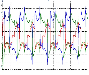
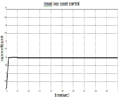
In this work the drive model with PI controller is developed and simulated in order to validate the four switch three phase inverter control of BLDC motor model. The reference speed is 2 rps and the closed loop response of rotor position, speed, current and torque are shown below.
[image:5.595.341.523.317.470.2]Fig 8: Stator current output waveform
Fig 9: Simulation output of torque curve
PI Controller
Four Switch Three Phase
Inverter BLDC
MOTOR r*
r(t)
u(t)
Sinle-Neuron PI Controller
Four Switch Three Phase Inverter
PWM Generator
BLDC MOTOR
i(t)
Hall signal
[image:5.595.50.285.515.658.2]
Fig 10: Simulation output of rotor speed
5.
CONCLUSIONS
The steady state and dynamic performance of BLDC motor with speed and current algorithm is obtained from simulation results. A single-neuron adaptive PI controller is used by the outer loop to develop the performance of speed control. Finally, qualified performance was verified by simulation results under different work conditions, at different speeds, and under different loads. It should be noted that reducing the quantity of current sensor surely brings some negative impacts to the control system, such as maximum current limitation in certain modes. The simulation results show how speed current algorithm of BLDC motor is better in terms of response when compared to conventional methods
6.
REFERENCES
[1] K.-W. Lee, D.-K. Kim, B.-T. Kim, and B.-I. Kwon, “A novel starting method of the surface permanent-magnet BLDC motors without position sensor for reciprocating compressor,” IEEE Trans. Ind. Appl., vol. 44, no. 1, pp. 85–92, Jan./Feb. 2008.
[2] D.-K. Kim, K.-W. Lee, and B.-I. Kwon, “Commutation torque ripple reduction in a position sensorless brushless DC motor drive,” IEEE Trans. Power Electron., vol. 21, no. 6, pp. 1762–1768, Nov. 2006.
[3] F. Rodriguez and A. Emadi, “A novel digital control technique for brushless DC motor drives,” IEEE Trans.
Ind. Electron., vol. 54, no. 5, pp. 2365–2373, Oct. 2007. [4] C.-W. Hung, C.-T. Lin, C.-W. Liu, and J.-Y. Yen, “A
variable-sampling controller for brushless DC motor drives with low-resolution position sensors,” IEEE Trans. Ind. Electron., vol. 54, no. 5, pp. 2846–2852, Oct.
2007.
[5] S. Rajagopalan, J. M. Aller, J. A. Restrepo, T. G. Habetler, and R. G. Harley, “Analytic-wavelet-ridge-based detection of dynamic eccentricity in brushless direct current (BLDC) motors functioning under operating conditions,” IEEE Trans. Ind. Electron., vol. 54, no. 3, pp. 1410–1419, Jun. 2007.
[6] G. J. Su and J. W. Mckeever, “Low-cost sensorless control of brushless DC motors with improved speed range,” IEEE Trans. Power Electron., vol. 19, no. 2, pp.
296–302, Mar. 2004.
[7] C. T. Pan and E. Fang, “A phase-locked-loop-assisted internal model adjustable-speed controller for BLDC motors,” IEEE Trans. Ind. Electron., vol. 55, no. 9, pp. 3415–3425, Sep. 2008.
[8] L. Parsa and H. Lei, “Interior permanent magnet motors with reduced torque pulsation,” IEEE Trans. Ind. Electron., vol. 55, no. 2, pp. 602–609, Feb. 2008 [9] D.-H. Jung and I.-J. Ha, “Low-cost sensorless control of brushless DC motors using a frequency-independent phase shifter,” IEEE Trans. Power Electron., vol. 15, no. 4, pp. 744–752, Jul. 2000.
[10]J.-H. Lee, S.-C. Ahn, and D.-S. Hyun, “A BLDCM drive with trapezoidal back EMF using four-switch three phase inverter,” in Conf. Rec. IEEE IAS Annu. Meeting, vol. 3, pp. 1705–1709., 2000.
[11]S.-H. Park, T.-S. Kim, S.-C. Ahn, and D.-S. Hyun, “A simple current control algorithm for torque ripple reduction of brushless DC motor using four-switch three-phase inverter,” in Proc. IEEE Power Electron. Spec. Conf., vol. 2, pp. 574–579,2003. [12]Q. Fu, H. Lin, and H. T. Zhang, “Single-current-sensor
sliding mode driving strategy for four-switch three-phase brushless DC motor,” in Proc. IEEE Ind. Technol. Conf., pp. 2396–2401,2006.
[13]S. B. Ozturk, W. C. Alexander, and H. A. Toliyat, “Direct torque control of four-switch brushless DC motor with non-sinusoidal back-EMF,” in Proc. IEEE Power
Electron. Spec. Conf., pp. 4730–4736., 2008. [14]Z. J. Jiang, D. G. Xu, and F. P. Wang, “An improved
development of four-switch low cost inverter on voltage equilibrium with magnetic flux control method,” in Proc. IEEE Elect. Mach. Syst. Conf., vol. 1, pp. 379–382,2003. [15]B.-K. Lee, T.-H. Kim, and M. Ehsani, “On the feasibility
of four-switch three-phase BLDC motor drives for low cost commercial applications: Topology and control,” IEEE Trans. Power Electron., vol. 18, no. 1, pp. 164–
172, Jan. 2003.
[16]J.-H. Lee, T.-S. Kim, and D.-S. Hyun, “A study for improved of speed response characteristic in four-switch three-phase BLDC motor,” in Proc. IEEE Ind. Electron. Soc. Conf., vol. 2, pp. 1339–1343, 2004. [17]H. Niassar, A. Vahedi, and H. Moghbelli, “Analysis and
control of commutation torque ripple in four-switch three-phase brushless DC motor drive,” in Proc. IEEE Ind. Technol. Conf., pp. 239–246.,2006.
[18]H. Niasar, H. Moghbeli, and A. Vahedi, “Adaptive neuron-fuzzy control with fuzzy supervisory learning algorithm for speed regulation of 4-switch inverter brushless DC machines,” in Proc. IEEE Power Electron. Motion Control Conf., pp. 1–5,2006,
[19]C.-T. Lin, C.-W. Hung, and C.-W. Liu, “Position sensorless control for four-switch three-phase brushless DC motor drives,” IEEE Trans. Power Electron., vol. 23, no. 1, pp. 438–444, Jan. 2008.
AUTHOR’S PROFILE
Rajasekaran P was born in Erode on 1985. He graduated in 2007 from Anna University Chennai. & post graduated in 2010 at Anna University Coimbatore. His currently working as Assistant Professor in the Department of EEE at Velalar College of Engineering and Technology, Erode. His area of interest Electrical Machines & Control Systems.