Embedded Dam Gate Control System using ‘C’ and
Visual Basic
Makesh Iyer
SIES Graduate Schoolof Technology, Nerul, Navi Mumbai
Shrikant Pai
SIES Graduate Schoolof Technology, Nerul, Navi Mumbai
Shubhangi Kharche
Assistant Professor SIES Graduate Schoolof Technology, Nerul, Navi Mumbai
Sneha Badri
SIES Graduate Schoolof Technology, Nerul, Navi Mumbai
ABSTRACT
Now-a-days water scarcity has become a serious problem in India and there are many factors responsible for this like improper supply of water from the dam, improper water saving systems, etc. but one major factor is the improper opening and closing of the dam gate according to the level of water in the dam. Also till date the control mechanism of the dam gates are done manually and using PLC. But there are lots of errors in manual method. Also the PLC based system is huge and hence suitable for major dams due to its cost. For medium and small dams like irrigation dams does not require such huge PLC systems. So to reduce these problems a mechatronic control system is proposed in this paper. This project is a AT89S51 microcontroller based dam gate control system which helps in keeping an eye on the frequent usage of water resources from dam for irrigation purposes and efficient operation of dam gate according to the level of water and also helps in indicating about flood to people living in the surrounding. This proposed mechanism of dam gate control reduces the water wastage and efficient usage of available water is ensured. Also there are heavy load shedding problems in the villages in almost all states of India. To overcome these problems the proposed dam gate control system can be combined with the operation of the geothermal and nuclear power plants for generation of electricity .
Keywords
water supply , dam gate , level monitoring , gate mechanism , microcontroller , DC motor, SIMO(simple input multiple output),visual basic 6.0
1.
INTRODUCTION
Embedded system is the combination of hardware and software co-design. Embedded systems are now-a-days playing a vital role in Engineering design process for efficient analysis and effective operation. From data analysis to hardware work, everywhere embedded products are now-a-days playing a vital role because of its reliability and real time operation execution. Due to time complexity in electronic aspects embedded systems have become a major part of our daily life. Our work describes the design of an embedded system for the “Embedded Dam Control System”. For industrial applications, home automation, and supervisory control applications, Personal Computer based electrical
appliances control is mainly useful. This control system gives exact concept of interfacing a high voltage electrical device or DC motor or DC / AC motor to personal computer system. This system facilitates us to control the gates of a dam depending on the water level automatically.
It consists of a set of sensors connected to a DC motor through an 8-bit microcontroller (AT89S51) [1]. The water level is detected based on the feedback from the mechanism used. Depending on the water level of the dam gate can be controlled using a DC motor and a personal computer. Due to this mechanism the water wastage can also be reduced and efficient utilization of water resources can be done. Also we can keep the record of the water usage and indications can also be given to the people at various situations eg. During heavy rainfall the chances of flood can be indicated.
The paper is structured to describe the literature survey in section 2, hardware implementation and operation in section 3, power generation mechanism in section 4, software description in section 5 followed by results , conclusion and future scope in sections 6 , 7 and 8 respectively.
2.
LITERATURE SURVEY
divison of reservoirs into upper and lower reservoirs and efficiently use the dam water. But the overall control was through PC and needed an operator. In our system we are mainly using microcontroller and a PC for the mode that microcontroller don’t support. So this reservoir sub division model can be merged with our system to get efficient resource conserving results. Marcel Nicola, Florin Velea have proposed a system [5] for effective control of Hydropower
Dam Spillway using PLC/SCADA system. But recently
Montanhydraulik [6] manufacturing company has installed a PLC based control system for controlling the operation of dam gates. This system was successfully installed on a large scale in foreign countries and the only dam in India where this system is installed is Indira Sagar Dam in Madhya Pradesh. But this PLC based system is costly and effectively applicable for major dams and not for small and medium dams like irrigation dams.Junmei Guo & Qingchun Chen also proposed a system using Fuzzy Logic in PLC/SCADA system [7] for the control of dam gate operation but since here too the PLC is used it can be suitable for major dams. Slivnik, T. Kodric, M.; Antauer, M. proposed a protection unit [8] for the dam gates which overcame some drawbacks of other existing system like not detecting anomalies, such as asymmetric movement of gates, faults in drive gearwheel etc. In our paper we have provided the limit switches for proper movement of gates. So we can use their system with our system to overcome other anomalies too. Our system is though proposed only for the proper control of gates but further it can be extended for proper supply of water for irrigation and to households too by implementing additional system which was proposed by Puig, V. , Ocampo-Martinez, C. Romera, J. Quevedo, J. Rodriguez, P. Campos, S. Negenborn. Their system [9] comprised of a model predictive control which considers the flow control strategies of water in dams. In reality there are many problems that occur in dams like deposition of silts, sediment souringwhich creates negative impact on flood control and water draining, water body quality, aquatic biology and marine navigation, etc.
So to avoid these problems we have to take some feasible measures of disaster reduction which was proposed by Lihua Feng & YanWang. Their proposed paper [10] clearly explains the above mentioned factors and their eradication measures.
3.
HARDWARE IMPLEMENTATION
AND OPERATION
3.1
Sensor
For implementing our proposed system we used normal single strand conductors but when implemented we didn’t get fruitful results. There was not enough flow of current in conductors to effectively trigger the microcontroller. So we made a sensor PCB with etched conducting strips on it sensing various levels shown below in fig.3. If implemented in real, this PCB sensor can be implemented but by applying AC power to it or we can also use magnetic pressure sensors or some other industry purpose level sensors. Further as a part of our sensor circuit we are using four npn transistors (BC 549) for each of the sensor. These transistors amplify the sensor output so that it can have enough strength to trigger the microcontroller. Fig.1 depicts the sensor circuit in which five sensors are used at various levels (very low,1/4,1/2,3/4,full).Except the very low level sensor all others are connected to the transistors and whenever water level increases or decreases and comes in contact with each sensor the corresponding transistor conducts and amplify the sensor output . Special arrangement is made to indicate the various water levels using an LCD display at the operator control panel. When water reaches each and every level then respective level value programmed in microcontroller will be indicated in LCD and the operator will either open/close the gate. The main reason behind using the transistor amplifiers after the sensors is to provide sufficient energy to the sensor output to trigger the microcontroller.
3.2
Block Diagram
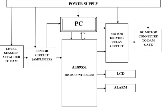
Fig. 2 depicts the block diagram of Microcontroller AT89S51 based Dam Gate Control System. The proposed system uses five sensors to sense various levels of dam water. Whenever the water level rises or decreases and comes in contact of any sensor then the circuit is complete and current flows due to which the corresponding transistor conducts and circuit is closed. The output of the sensor circuit triggers the microcontroller. Whenever the water level rises above the highest level or decreases below the lowest threshold level then the sensor circuit triggers the microcontroller. According to the code written and burnt in the microcontroller, it will
[image:3.595.30.552.249.599.2]drive the DC motor through the motor driver relay circuit and the dam gate connected to the DC motor [11] will also move and it will get opened or closed according to the water level. To operate the gates of dam at the water levels which are not supported by the system an operator can be placed at the control room to control all the operation of the dam. The operators system will be connected to the microcontroller through the USB interface. This is the main interface through which the operator is connected to the microcontroller and without this interface code cannot be burnt in the controller. Also the operator is provided with the facility to indicate the people living in the surrounding areas of the dam about the water usage for irrigation and alarm the people to let the released water from dam to their fields.
Fig. 2 Microcontroller AT89S51 based Dam Gate Control System.
3.3
Implementation of Proposed System
In this section the hardware that we have developed to implement the proposed system has been explained. There are various components we used to implement this system. The following figures are the snapshots of the system we implemented. The whole system is divided into various sections and each are explained separately.
Fig 3 represents the five water level sensors that are etched on a PCB. This PCB will be placed in the dam. Whenever the water level touches each sensor line then the corresponding
transistor amplifies its input and this sensor data is used to trigger the microcontroller. This kit is interfaced with the microcontroller kit. The main reason behind using the transistor amplifiers after the sensors is to provide sufficient energy to the sensor output to trigger the microcontroller.
Fig 4 shows the LCD interfaced [11] to the microcontroller kit. The LCD is used for indicating the operator about the frequent level changes in the dam. LCD will be placed in the control panel. The LCD used is a 16x2 LCD with the green backlight feature. In this LCD the water level will be continuously displayed according to the changes in the water level in dam.
POWER SUPPLY
AT89S51
MICROCONTROLLER
LEVEL SENSORS ATTACHED
TO DAM
SENSOR CIRCUIT (AMPLIFIER)
MOTOR DRIVING
RELAY CIRCUIT
DC MOTOR CONNECTED
TO DAM GATE
LCD
ALARM
Fig .3 Sensors with Amplifier
[image:4.595.54.298.221.375.2]Fig .4 LCD indication of water level to operator
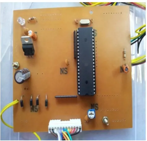
Fig .5 controller kit with power supply
Fig 5 shows the microcontroller kit with power supply. AT89S51 is the microcontroller used in this system with 8MHz crystal frequency. The microcontroller is programmed to control the operation of gates and indicate the operator the exact level of water in dam using LCD. Port 0 is interfaced with the LCD module and Port 2 is interfaced with the motor control circuit. Port 1 is interfaced with the sensor circuit. +5V power supply is given to the system.
Fig 6 shows the motor driver circuit using electromagnetic relays [11]. Four SPDT relays are used one for opening the gate, one for closing the gate, one to turn ‘ON’ the buzzer/alarm and last one for future use. Four Transistors (BC 549) are connected to each relay to activate them. Also four LED’s are connected to each relay and whenever the relay is ON then the corresponding LED will glow.
Fig .6 motor driver circuit
Fig .7 Dam Gate Arrangement With Motor
[image:4.595.323.535.370.651.2] [image:4.595.55.293.411.639.2]movement will be On but as soon as it touches the switch then the supply to motor is cut and the gate movement stops. Similarly the mechanism works while closing of gates. This feature monitors the proper operation of dam gates.
4.
POWER GENERATION
MECHANISMS
In this section, we describe the power generation in geo thermal and nuclear power plants and then we explain dam gate systems application in the afore mentioned power plants.
A.
Geo-thermal power plants.
In geothermal thermal power plants [12], water from the core of the earth at around 20,000 feet deep is sucked and it is processed at various pressure levels. In this processing water collected from earth is boiled at various temperature levels and the superheated steam generated from this process is accelerated on the turbines of the power generators through which electricity is generated.
B.
Nuclear Power Plants
.In nuclear power plants water is the main medium which is used for the generation of power except the fact that nuclear materials are used for processing. In this plants the nuclear materials undergo nuclear fission as a result give tremendous heat energy. This heat energy is used to heat the water through which superheated steam is generated and this steam is finally accelerated over the generator turbines resulting in the generation of electricity.
C.
Use Of Dam Gate System in Power
Plants
Now the role played by the dam gate control system is the supply of the water from the dams to the above power plants through separate pipe lines in case the amount of water available to them is not adequate. In case of geothermal power plants instead of using water from the earth’s core solely, just 50 to 60% from the core can be utilized and rest amount of water can be taken from the dam for power generation. In this way water content in core will also not extinct and power generation will also be un-stoppable.
5.
SOFTWARE DESCRIPTION
5.1 ‘C’ programming
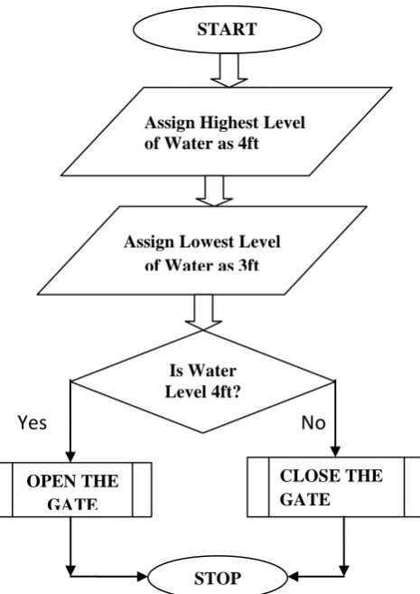
We used BASCOM - 8051 software as the integrated development environment for writing micro-controller code in the C language. Fig. 8 signifies the flowchart of the operation of the system in AUTO mode i.e., the role of the microcontroller in the system. In AUTO mode the operation of dam gate is controlled by microcontroller. Accordingly the operation in AUTO mode is clearly explained in the flowchart. In this mode the highest level of water is assumed to be 4ft and the lowest level to be 3ft according to our model. Whenever the water level reaches the highest level (4ft) then the controller will open the gate and water level will decrease and as soon as it reaches the lowest level (3ft) the controller will close the gate.
Yes No
[image:5.595.306.539.82.411.2]Fig. 8 Flowchart of system operation in ‘AUTO’ mode
5.2 Visual Basic 6.0 code
We also used Visual basic 6 software based control panel providing the operator to control the system during manual mode. According to our proposed system an operator is available to control the gates at certain conditions that the system doesn’t support. Fig. 9 shows the control panel of the operator, used for level indication is developed using visual basic 6.0.
Fig. 9 Control Panel For The Operator
START
Assign Highest Level of Water as 4ft
Is Water Level 4ft?
CLOSE THE GATE OPEN THE
GATE
STOP Assign Lowest Level
of Water as 3ft
[image:5.595.317.555.542.741.2]The panel display includes a graph of water level wherein the level is indicated according to the increase/decrease in the water level. AUTO/MANUAL command is used to give the options for auto/manual operation of gate. The OPEN, CLOSE and STOP command is used for opening, closing and stopping the gate in manual mode. There are four options of ports provided with a CONNECT command which is used for interfacing the system with the PC. For auto mode an upper and lower limit are indicated for reference.
6.
RESULTS
The system we proposed has been successfully implemented and observed the results. We found that the time taken for the dam gate to open and close is accurately synchronized with the increase or decrease in the water level because of the use of Low Speed High Torque DC Reduction Gear Motor having 100 rpm. Due to the use of GUI operator control panel the dam gate can be opened or closed at any time as and when we require which increases the system reliability and flexibility. Fig. 9 shows the operator control panel. A graph is plotted continuously on the panel indicating the change in the water level every second which makes the system operator friendly and reduces his job of continuously monitor the water level in dam.
7.
CONCLUSION
The proposed mechanism of dam gate control reduces the water wastage, ensures efficient use of available water resources and generates more precise and accurate results. There is no requirement of human labourers for monitoring the level, just one operator is sufficient for opening and closing the gate according to sensor output. Due to the number of sensors being more we can open or close the dam gate whenever necessary knowing the accurate level of water. Also operation execution time is less. Also there are heavy load shedding problems in the villages in almost all states of India. So this dam gate control system operation can be combined with the operation of the geothermal and nuclear power plants for generation of electricity.
8.
FUTURE WORK
Since wired technology is used in our proposed system there is scope to further modify it by using wireless RF technology.Thus the communication between the controller and the driving element can be established wirelessly. Improvements can be made with minor changes in this model by eliminating the operator and providing the complete control to microcontroller (automatic level control). It can be used for level monitoring and control in industries. Control of irrigation dam and other large dams used for power generation and water supply should be different; as control of both types together will be very complex since there are total 5200 dams (approx.) in India. Therefore a major future work can be possible in which a centralized control of all the dams in a state using GPRS or other wireless technology under central government can be beneficial to the whole country.
9. REFERENCES
[1] www.keil.com/dd/docs/datashts/atmel/at89s51_ds.,pp 4-5, 12- 13. This reference is the datasheet of AT89S51 microcontroller. This datasheet helped us in interfacing the peripheral devices with the microcontroller using the pin configuration and their functions.
[2] Davidson, E.G. , ‘Control of hydro-electric plant’, ‘Generation, Transmission and Distribution, IEE Proceedings C’, Volume 133, Issue: 3 PP. 145 - 147, April 1986.
[3] Xavier Litric, ‘Robust IMC Flow Control of SIMO Dam-River Open-Channel Systems’, ‘IEEE Transactions On Control Systems Technology, Vol. 10, NO. 3, PP. 432-437, 2002’.
[4]
Syed Sheraz Mohani, Syed Muhammad Umar Talha, Syed Hassan Ahmed and Mansoor Ebrahim, ‘Design for Irrigation and Monitoring System of an Automated Dam’, ‘Proceedings of the MultiConference of Engineers and Computer Scientists 2012 Vol II, IMECS 2012, March 14-16, 2012, Hong Kong.
[5] Marcel Nicola, Florin Velea, ‘Automatic Control Of A
Hydropower Dam Spillway’, ‘Annals of the Universityof
Craiova, Electrical Engineering series, No. 34, 2010;
ISSN 1842-4805’.
[6] http://www.montanhydraulik.in/montanhydraulik-india-en-civil-engineering-references-indira-sagar-dam.html This web provides the detailed information of the Montanhydraulik industry that implement PLC based Dam Projects.
[7] Junmei Guo , Qingchun Chen , ‘An Application of Fuzzy Control Based on PLC in Rubber Dam Monitoring System’ , ‘International Conference on System Science, Engineering Design and Manufacturing Informatization (ICSEM), 2010’ , Volume 2 ,PP. 266-269 ,Nov.2010. [8] Slivnik, T. Kodric, M.; Antauer, M. , ‘Protection of gate
movement in hydroelectric power stations’ , ‘Electrotechnical Conference, 2000. MELECON 2000. 10th Mediterranean’ , Volume 3 , PP. 1043 – 1046 , May 2000.
[9] Puig, V. , Ocampo-Martinez, C.; Romera, J.; Quevedo, J.; Rodriguez, P.;de Campos, S.; Negenborn, R. , ‘Model predictive control of combined irrigation and water supply systems: Application to the Guadiana river’ , ‘9th IEEE International Conference on Networking, Sensing and Control (ICNSC), 2012’ , Conference Publications , PP 85 - 90 , April 2012.
[10] Lihua Feng, Yan Wang, ‘Environmental Effect of Tidal Gate and Measures of Disaster Reduction - A Case Study of the Tidal Gate on Yaojiang River’, ‘5th International Conference on Bioinformatics and Biomedical Engineering, (iCBBE) 2011’ , Conference Publications , PP 1-4, May 2011.
[11] Mazidi and Mazidi, ‘Microcontrollers’, Prentice Hall Publications, Pg 284-290,300-310,428-430,441-450.