Implementation of Greedy Sequential Unique Path
File
Carving
Algorithm for
Fragmented Bitmap Image Files
K. Srinivas
Sree Chaitanya College of Engg. Karimnagar,Andhra Pradesh, India
T. Venugopal,Ph.D
JNTUH College of Engg Nachupally,Karimnagar, Andhra Pradesh, India
ABSTRACT
Digital Forensic Analyst encounters a mixed file fragments in the absence of File Table information i.e., files‟ metadata. File Carving is a process of reconstructing files from mixed file fragments without using files‟ metadata. File Carving is an interesting and challenging problem in digital forensics and Data Recovery. Recently there have been number of research papers in the area of File Carving. In this paper authors describe File Carving and present its Literature Survey. The implementation of Greedy Sequential Unique Path File Carving algorithm for 4-bit bitmap files, with the help of function prototypes using C language and brief explanation of these prototypes is explained. The experimental results are also shown. The experimental results show that the files can be reconstructed from their fragments without knowing files‟ metadata. However there are limitations of these methods as mentioned in section 5.
General Terms
Greedy Algorithms,, File Carving, File Fragmentation, Digital Forensics, Data Recovery, Disk Clusters, Graph, Paths in a Graph.
Keywords
GSUP4Bit Algorithm, tail bmp, head bmp, Data of Image File, The Challenge File, Spurious Disk Cluster, Successor Cluster.
1.
INTRODUCTION
Day by day usage of digital devices like mobiles, computers etc. are increasing enormously. Though their use for betterment of the society is significant, their use for anti social activities is alarming. Hence development and upgrade of technology continuously to counter the tactical use of the digital devices by anti-social elements are needed.
When investigating agencies acquire any digital device suspecting to have been used by anti-social elements, they are sent to forensic experts for critical examination. When a forensic expert receives devices such as mobiles and hard-disks, then conventional methods of finding information from such devices is not sufficient. For example, a terrorist had created image files containing the sketches of their plans to execute terrorist activities and deleted all such files or formatted the disk on suspecting the raid. When files are deleted or disk is formatted, Operating System updates file tables to reflect the new state of the disk but do not wipeout the data clusters. Conventional methods do not show such
files though the data of such files is not wiped out in data clusters. Therefore conventional methods cannot show any clue for the law protectors though present on the disk. Files are fragmented on disk for the following reasons.
1. File extension
2. Non-availability of contiguous space for new files. 3. File storage strategy of Operating System.
Consider the files named A, B and C on disk in contiguous area of the disk. After creating the three files, if file A is extended, then file A on the disk is fragmented.
The required amount of free space for a new file may not be available contiguously on disk and the total fragmented free space is greater than the required amount of free space. UNIX Operating System fragments a file after allocating certain number of contiguous clusters because the next contiguous cluster is used for storing cluster numbers of subsequent allocated clusters.
In the absence of File Table information it is difficult to reassemble fragmented files. This problem is encountered by a forensic expert while examining a disk. The problem is also encountered by data recovery experts.
The task of reassembling fragmented files without using file table information is called File Carving.
Recently researchers have started developing technology for File Carving. Literature survey in the area of File Carving has been presented and details of implementation of one of the algorithms i.e., Greedy Sequential Unique Path Algorithm have been presented
This paper is organized as follows. There are seven sections. Literature Survey on File Carving is presented in section 2. The internal structure of 4-bit bitmap file, an input file for the File Carving problem, identification and elimination of irrelevant clusters and description of GSUP4BIT algorithm are presented in section 4. Experimental setup for the implementation of GSUP4BIT algorithm and results are presented in section 5. Finally, in section 5, the limitations of GSUP4BIT algorithm and a common problem noticed in all the algorithms discussed in [1], [2], [3] and [4] have been presented.
2.
LITERATURE SURVEY ON FILE
CARVING
Researchers have developed recently and are still developing new technology for addressing various problems of File Carving.
Automatic reassembly of fragmented document files is described in [1]. The logic of finding a next cluster C2 for a
given cluster C1 is as follows. A word that spans the cluster
present in the clusters then C2 is considered the next cluster
for the current cluster C1. This approach is not suitable for
reassembling variety of document fragmented files and therefore this problem is addressed by context based statistical models [1].
Automatic reassembly of fragmented image files is described in [2]. To determine correct reordering of fragments of a file, a smoothness property of an image is utilized. With this approach, a fragment Aj would be considered to be a likely
candidate fragment to follow Ai if the ending „width‟ numbers
of pixels of Ai are „smooth enough‟ with starting „width‟ number of pixels of Aj. The details finding the parameters
„width‟ and „smooth enough‟ are described in the next section. A hard disk contains millions of clusters. For finding Aj that
follows Ai in original document, every other cluster than Ai
needs to be examined. This approach needs a support of fastening the process of finding a successor fragment of a given fragment. Fast object validation concepts are introduced for quickly rejecting the fragments that might not be the candidate fragments for the fragment Ai and retain only
less number of fragments as candidates for Aj as the successor
fragment in original file [3].
[image:2.595.333.526.431.703.2]File carving is refined to consist of four steps [4]. This refinement is due to the fact, as found by researchers, that fragmentation is not by cluster by cluster but each fragment consists of a set of clusters and number of fragments is normally not greater than 4. Researchers have also found that many files are bi-fragmented i.e., number of fragments in a file is two. The four steps are 1) To identify beginning cluster of a file 2) To test sequentially each cluster and find fragmentation point or end of the file 3) If fragmentation point is detected, find starting point of next fragment 4) Continue with step 2 from starting point of next fragment. For identifying fragmentation point two tests have been projected. They are Syntactical tests and statistical tests.
Table 1. Comparison of Existing Techniques Existing
Technique
File carving
task Remarks
Dictionary based File Carving and File Carving using context based statistical
models[1]
File Carving of Document
Files
Prohibitively expensive Time and
space complexities and file type specific file carving
Greedy sequential/Parallel Unique/Nonuniqu
e Path Algorithms[2]
24-bit Bitmap Image File
carving
Prohibitively expensive Time and
space complexity issues and file type specific file carving
Fragmentation point detection techniques[3]
To speed up File Carving using results
of Garfinkel‟s
research
Time and space complexity issues
solved to some extent but the techniques are file
type specific.
The Table 1 gives the comparative study of the existing techniques of file carving and their limitations.
3.
REPRESENTATION
OF
IMAGE
FILE
CARVING
PROBLEM
WITH
A
GRAPH
A disk D consists of a sequence of clusters data. Each cluster can be represented as one node of a graph. An edge connecting the nodes I and J has a weight WI, J that represents
the closeness of the two clusters represented by the two nodes. So the disk is represented by a complete graph. Each image file is represented by one path in the graph. The starting node of each path is one separate node corresponding to a header of each image file. Starting with a node representing a header of a bitmap image file, each successor node is found by applying greedy strategy. For g given node a successor node is an adjacent node with minimum weight. As no cluster can belong to more than one image file every path is a unique path. The paths are found sequentially i.e. one after the other. That is images are reconstructed one after the other. Therefore file carving problem (i.e. images reconstruction without using file table information) is a problem of finding unique paths P1, P2,
... , PN, one after the other, in a graph G representing the disk
D. Putting all this together the name, “Greedy Sequential Unique Path” is given to this algorithm by researchers Pal et al [2].
4.
IMPLEMENTATION
OF
FILE
CARVING ALGORITHM
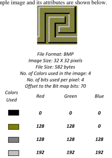
It is essential to know the details of image storage (explained below) before the implementation of File Carving. An example image and its attributes are shown below.
File Format: BMP Image Size: 32 X 32 pixels
File Size: 582 bytes No. of Colors used in the image: 4
No. of bits used per pixel: 4 Offset to the Bit map bits: 70 Colors
Used Red Green Blue
0 0 0
128 128 0
128 128 128
192 192 192
Fig. 1 A Carved Stone Image File and its Attributes
The image file data for the above example image is shown and explained in the next section.
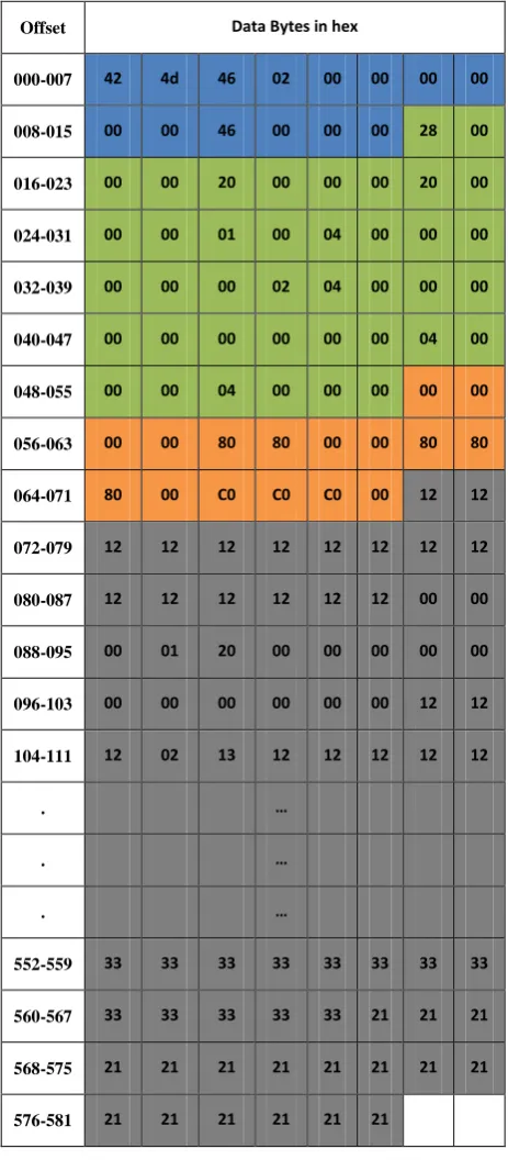
[image:2.595.55.279.454.725.2]4.1 The Bmp Image File Data
[image:3.595.48.280.84.613.2]The File Data for an image shown in Figure 1 is shown in Table 2. It includes 54 bytes header, Color table and color of each pixel. The data is shown in hex. Offsets are shown in decimal. The hex values at offsets 1 and 2 are 42 and 4d representing characters B and M. This information is used to identify disk clusters containing image header.
An assumption that the cluster size is 512 bytes is made. The results shown in this paper are based on this assumption. Data at byte offsets from 1 to 14 contain bitmap file header. This includes file type, file size, reserved field 1, reserved field 2 and offset of image data with their values in hex 424d, 246, 0, 0 and 46 respectively. This data indicates that it is a file of type bitmap of size 582 bytes. And color of each pixel
is stored in this file starting at byte offset 70. This portion of the data is shown with blue background.
Byte offset from 14 to 54 contain bitmap information header. This includes width of the image (byte offset from 18-21), height of the image (byte offset from 22-25), number of bits used to represent each pixel (byte offset from 28 to 29) and number of colors used (byte offset from 46 to 49) with their values in (hex, decimal) are (20,32), (20,32), (4,4) and (4,4) respectively.
Byte offset from 14 to 54 contain color table defining four colors used in the image with (R,G,B) components for each color equals to (0,0,0), (128,128,0), (128,128,128) and (192,192,192) respectively. For storing each pixel, index of the color in the color table, is stored in the file. That is why; there is no nibble value greater than 3 from byte offset 70 onwards.
This is also the first cluster of an image. The bytes from offset 70 to 511 represent the color of pixels in the first cluster of the image with an assumption that the cluster size is 512 bytes. The remaining pixels colors (i.e. indexes of the corresponding colors in color table) are stored in another cluster. And these two clusters need not be in sequence on the disk.
4.2 The Challenge File
The Challenge File is used to simulate a disk. In this Challenge file, mixed fragments of files have been copied for simulating a disk. Each fragment is of fixed size because cluster size on disk is fixed. The size of a fragment is fixed to a sector size i.e.512 bytes for simplicity. So a Challenge file consists of fragments of number of files in mixed order.
4.3
Discarding Spurious Disk Clusters
The example image (Fig 1) is a 4-color image and 4 bits represent each pixel. That is, each pixel is represented by one of the 4 indices (0/1/2/3) into the colour table. If a nibble value in any image is greater than 3, it is not a valid index. As shown in the table-1, no index is greater than 3. Disk clusters having a nibble value greater than 3 cannot be part of this image. Therefore all disk clusters having a nibble value greater than 4 in it, can be discarded while processing any 4-bit, 4 colour image. The advantage of discarding spurious disk clusters with this method is not possible in 16-bit, 24-bit and 32-bit bit-map images reconstruction.4.4 Physical Storage of the Image File’s
Data on the Disk
Mostly the file data is fragmented on the disk for number of reasons explained in section 1. When the example image file is stored on the disk, how it might get stored on it in clusters I and J, is shown in the following figure.
1 2 3 ... I ... J ... N
DISK
Cluster I Cluster J
Fig. 2 File fragmentation on Disk
The above figure shows that the disk has N clusters numbered as 1, 2, 3, ...,, N. The image is stored on the disk not contiguously but fragmented at cluster I and cluster J.
Offset Data Bytes in hex
000-007 42 4d 46 02 00 00 00 00
008-015 00 00 46 00 00 00 28 00
016-023 00 00 20 00 00 00 20 00
024-031 00 00 01 00 04 00 00 00
032-039 00 00 00 02 04 00 00 00
040-047 00 00 00 00 00 00 04 00
048-055 00 00 04 00 00 00 00 00
056-063 00 00 80 80 00 00 80 80
064-071 80 00 C0 C0 C0 00 12 12
072-079 12 12 12 12 12 12 12 12
080-087 12 12 12 12 12 12 00 00
088-095 00 01 20 00 00 00 00 00
096-103 00 00 00 00 00 00 12 12
104-111 12 02 13 12 12 12 12 12
. …
. …
. …
552-559 33 33 33 33 33 33 33 33
560-567 33 33 33 33 33 21 21 21
568-575 21 21 21 21 21 21 21 21
[image:3.595.311.548.629.724.2]4.5 Finding Successor Cluster
The colour information of pixels of an image is stored on multiple clusters on the disk, if the image cannot fit into one cluster. Given the first cluster of the image, the logic of finding the next cluster is described from step five to step nine of the algorithm described in next section. This logic is also the basic principle of finding the next cluster, given any one cluster of the image. The logic is explained for the bmp image of size 32 x 32 pixels, 4-bit and 4color. This image is stored on 2 clusters when stored on Challenge, because the image file is 582 bytes and the cluster size is 512 bytes. Tail means the last 16 bytes on the given cluster. Head means the first 16 bytes on the next cluster. 16 bytes Tail (or 16 bytes Head) stores colour information of 32 pixels. Head and Tail do not differ much in colour in any natural image. By using the Tail and Head, the border comparison of two pieces of a paper containing any natural image can be initiated. The corresponding colours along the borders of the two pieces are almost the same. Humans reassemble torn pieces of a paper containing an image by comparing the borders of two pieces. When the borders match, the two pieces are reassembled.
5.
GSUP4BIT ALGORITHM
GSUP4BIT algorithm is a Greedy Sequential Unique Path algorithm for reconstructing 4-bit bitmap file fragments.
5.1 Basics Of Gsup4bit
The word „Greedy‟ is used because this algorithm is a greedy algorithm. In general a greedy algorithm consists of n steps with each step selecting an item that minimizes the cost or maximizes the profit. In this algorithm it selects a successor cluster in each step that minimizes the difference of colours of corresponding clusters tail and head.
The word „Sequential‟ is used because this algorithm reconstructs multiple images one after the other „parallel‟ algorithm constructs multiple images concurrently.
The word „Unique‟ is used because once a cluster is assigned to a particular image file during reconstruction; it will not be considered and assigned for any other image file because the same cluster can not belong to multiple images files.
The word „Path‟ is used because this algorithm represents the problem of reconstructing images as a problem of finding a path in a graph. The nodes of the graph are clusters and edge cost of an edge (I,J) represent the total of differences of corresponding colours along the borders i.e., head and tail. For a cluster I the successor cluster is a cluster J that has minimum edge cost as compared to any other cluster. This algorithm initially identifies header clusters from the challenge file. Let H be the set of header clusters identified from S, the set of clusters in the challenge file. By decoding header clusters, the attributes of bitmap files are obtained. It reconstructs the image files present in the challenge file as follows.
For each header cluster one image file is reconstructed. Starting with the header cluster the subsequent clusters in the original image are found as follows.
Initially current cluster i is set to header cluster and used cluster set C is also set to header cluster i.e., C= { I }. The next cluster in the original image for the current cluster is obtained by comparing tail of current cluster with the head of the cluster j where j є S – E – C and the cluster j is one which satisfies smoothness property with cluster i. Then j is added to the used cluster set C i.e., C = C U { j }. Then the current cluster is set to j i.e. I = j. Following the above logic, clusters to the set C are added until the image file is reconstructed..
5.2 Algorithmic Steps Of Gsup4bit
The details of this algorithm are explained with the help of following steps.
i. Obtain the Header Clusters; H1, H2, … , Hn. For
each permutation of the Header Clusters list, perform steps ii and iii.
ii. Initialize Used Clusters array to contain the cluster numbers of Header Clusters. Initialize used cluster count to n.
iii. For each Header Cluster, perform step 4 to 6. iv. Obtain the following information about the image
available on the disk. Output the Header Cluster No. a. Size of the image file.
b. Total number of clusters of the image. c. Width (w) of the image.
d. Color Table.
e. Number of colors used. f. Maximum index.
v. Obtain Border bytes on the header cluster, representing w number of pixels of the image into „tailbmp‟.
vi. For each Data Cluster on the disk, perform the steps vii to xii.
vii. Test if the current data cluster is in Used Clusters list. If yes, skip this cluster and consider the next Data Cluster.
viii. Obtain the initial border bytes representing „w‟ indices of colors of the pixels into a „headbmp‟. ix. If any index is greater than Maximum Index, skip
this Data Cluster and proceed with the next data cluster.
x. Calculate Candidate weight of the Data Cluster and store it in „weights‟ array.
xi. Next Cluster is the one with minimum Candidate Weight. Output the Data Cluster No as the successor.
xii. Set the Current Cluster to Next Cluster.
xiii. Construct the image file by copying all the bytes from the output clusters in the same order output by the algorithm.
The above algorithm has been coded using C language and tested with the Challenge file that contains mixed file fragments. The experimental setup and the results are explained in the next section.
2.
EXPERIMENTAL
SETUP
AND
RESULTS
For implementing the GSUP4BIT algorithm, function prototypes are designed and implemented using C language. In this section, results of the experiments are shown.
5.3
FUNCTION PROTOTYPES
The following is the list of prototypes of functions developed and tested for the implementation of Greedy Sequential Unique Path Algorithm up to 4bit Bitmap Images.
i. int readcl(int clno , char buf[]) ;
ii. int IsHeader(int clno,char *cldata,int showattr=0) ; iii. int getheaders(int from,int to,int headers[]) ; iv. void getattributes(char buf[],bmpfh *fh,bmpih *ih) ;
vi. unsigned long findweight(int nbytes,uc h[],uc t[],int max,color ct[]) ;
vii. int min(unsigned long int x[],int n) ; viii. int in(int used[],int usedcnt,int cur) ; where uc,bmpfh,bmpih and color are typedef unsigned char uc ;
typedef struct bmpfh
{
char imgtype[2] ; long int filesize ; int reserved1; int reserved2 ; long int bmpoffset ;
} ;
typedef struct bmpih {
unsigned long int size ; unsigned long int imgwidth ; unsigned long int imgheight ; int planes ;
int bitsperpixel ;
unsigned long compression ; unsigned long biSizeImage ; unsigned long bixplspermeter; unsigned long biyplspermeter; unsigned long usedcolorcount; unsigned long biclrimportant;
} ;
typedef struct color
{
unsigned char blue ; unsigned char green ; unsigned char red ; unsigned char res ;
} ;
The function readcl() reads the data of specified cluster into the specified buffer from the Challenge File. On error, it returns –1. If the cluster data contains a Bit map Header, it returns, –clno, otherwise, it returns clno. This function identifies Bitmap header by testing if the data starts with the bytes (in hex) 42 and 4d.
The function IsHeader() is to test whether a specified cluster is a header cluster. If required, the function can also display the attributes of the image like width, height, file size etc. It returns TRUE, if the cluster is a header, FALSE otherwise. The function getheaders() is to gather header clusters numbers in the specified range of clusters. It returns count of header clusters and header cluster numbers it has encountered during scanning the specified range of clusters.
The function getattributes() is to return the struct variable pertaining to the header of a Bit Map Image, by taking the header cluster data as an input. That is, it decodes the header and obtains image attributes.
The function compare() is to return the difference between the two colours specified. It is used to find how close the two pixels are in colour. The closeness of the pixels is returned as (abs(c1.red-c2.red)+abs(c1.green-c2.green)+abs(c1.blue-c2.blue))/3. Lower the value returned by the above expression for the two pixels those are closer in color. It is clear that if the two pixels are having the same color then the function returns zero.
The function findweight() calculates the candidate weight. The candidate weight is calculated by comparing „width‟
number of last pixels of Ith clusters with the same number of initial pixels of cluster Jj. The candidate weight is a measure to indicate how close, in terms of an image, the cluster I and cluster Jj are. Lesser the value of candidate weight between clusters I and j more closely the clusters I and J are. A cluster is represented by a node of a graph where as the weight is represented as an edge weight of and edge comprising of nodes I and J corresponding to two clusters I and J. That is a disk is represented in the form of a graph where in each node represents a cluster and each edge represents candidate weights between the two clusters.
The function min() is to find and return a cluster whose candidate weight is minimum. That is, it returns the cluster closest to the given cluster. That is, it finds adjacent cluster J for the specified cluster I in original file.
The function in() is to find whether a given cluster is already assigned to any image; If yes, it returns 1, else 0. This function is used to avoid assigning the same cluster to more than one image. Thus unique list of clusters for each image is generated.
6.2 IMPLEMENTATION OF GSUP4BIT
ALGORITHM
Using the implementations of function prototypes described in section 6.1, a greedy algorithm is implemented in a C function called GSUP4Bit(). This function finds N paths P1, P2, ... , PN
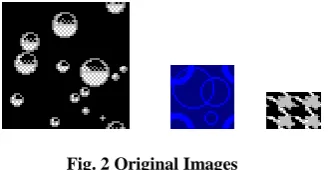
sequentially. Each path represents one image file. Starting with a node corresponding to a header cluster each successive node corresponding adjacent clusters in a original file is found and the corresponding cluster data is read from the Challenge file and written to a file. The reconstructed files are named as file1.bmp, file2.bmp, ... , fileN.bmp. The input to this file comes from the Challenge file which is constructed by writing the data of the image files shown in Fig. 2 below.
[image:5.595.352.518.442.527.2]
Fig. 2 Original Images
The attributes of the above images are shown in Table 3 shown below.
Table 3. Attributes of Tested Images
The total number of clusters in the Challenge file is therefore 8. In addition to these clusters, a data from other clusters is also written to the Challenge file making the total number of clusters equals to 50. The other clusters data is written to the Challenge file just to ascertain the finding of the correct ordering of the clusters by the algorithm in the presence of irrelevant data in it because this is the practical situation on a disk.
Original Images Reconstructed Image
Sequence generated
Bubbles.bmp file1.bmp 1,2,3,4& 5
Circles.bmp file2.bmp 6
6.3 EXPERIMENTAL RESULTS
Keeping the limit to 50th cluster,( #define LIMIT 50) the program found the bit map image headers at cluster numbers 0, 5 and 6. It then reconstructed three images file1.bmp, file2.bmp and file3.bmp in the current working directory. That is it found the correct sequence of clusters for the first image as shown in Table 4.
Table 4. Generated Cluster Numbers Sequence
When the above files named file1.bmp, file2.bmp and file3.bmp were opened and viewed in Windows Paint Application they resembled the original images shown in Fig. 2.
6.4 LIMITATIONS
The algorithm GSUP4BIT will fail when image data at cluster boundaries are such that they do not satisfy smoothness property of images.
Given one cluster of a particular file, many clusters in a Challenge file i.e. disk need to be searched, for finding its next cluster in original file.
This algorithm as it is cannot be used for other image file types and other sub types like 24-bit bitmap image files. For 24-bit bitmap files minor changes in the C source code to be made in a function called findweight(). However, for dealing with other file types larger modifications in the source code to be made. Data recovery experts and digital forensic experts may also want to recover non-image files and this source code needs to be refurbished entirely.
6.5 CONCLUSION
Digital forensic analysts and data recovery experts encounter mixed file fragments and have no clue about correct ordering of the clusters to make up files. To solve this challenging problem the existing forensic tools like scalpel and foremost fail because these tools assume that files are not fragmented on the disk. Therefore, researchers have started developing technology for automatic reconstruction of mixed fragmented files in the absence of file table information and this area is called File Carving.
In this paper authors have presented literature survey of latest developments in File Carving and carried out experiments based on one of the research papers. The experiments gave motivating results in File Carving. But the solution space is very large and technology is file type specific. Authors would like to continue conducting experiments based on some more papers on File Carving. In our future research, authors would like to investigate if there can be a generalized solution that works for all file types, present and future, and reduce the solution space for finding the next cluster given one cluster of a particular file.
6.6 ACKNOWLEDGEMENT
Authors would like to thank all the faculty members of department of Computer Science and Engineering, Sree Chaithanya College of Engineering, Karimnagr, Andhra Pradesh, India for their whole hearted support and encouragement in carrying out experiments in labs.
7.REFERENCES
[1] Kulesh Shanmugasundaram, Nasir Memon, Automatic Reassembly of Document Fragments via Context Based Statistical Models, Department of Computer and Information Science Polytechnic University Brooklyn, NY 11201.
[2] Nasir Memon, Anandabrata Pal, “Automated Reassembly of File Fragmented Images Using Greedy Algorithms”, IEEE Transactions on Image Processing, Volume 15, No.2, February, 2006. [3] Simson L. Garfinke, “Carving contiguous and
fragmented files with fast object validation” ELSEVEIR digital investigation 4S (2007) S2–S12. [4] Anandabrata Pal, Husrev T. Sencar, Nasir Memon
“DetectingFile Fragmentation Point using Sequential Hyposthesis Testing”, ELSEVIER digital Investigations 5 (2008) s2-s13
[5] Anandabrata Pal, Nasir Memon – “The Evolution of File Carving”, IEEE signal processing magazine [59] march 2009
[6] Maurice J Bach Pearson, “The Design of the Unix Operating System” (Pearson Education) – 2003.
Header Cluster
File Size
#Clus-ters
Img
Size Bpp
No of colors
0 2118 5 64x64 4 4
5 190 1 32x32 1 2