2018 International Conference on Applied Mechanics, Mathematics, Modeling and Simulation (AMMMS 2018) ISBN: 978-1-60595-589-6
Study on Large Scale Islanded Onshore Wind Power Transmission via
VSC HVDC System
Rong CAI
1,*, Kaushik HORE
2, Xiao-bo YANG
1, Li-bo ZHANG
3,
Hong SHEN
4and Qing HE
41ABB (China) Co., Ltd. Chaoyang District, Beijing 100015, China
2
ABB (India) Co., Ltd. Vadodara, India
3State Key Laboratory of Power Grid Safety and Energy Conservation (China Electric Power
Research Institute), Haidian District, Beijing 100192, China
4
Global Energy Interconnection Group Co., Ltd., Xicheng District, Beijing 100031, China
*Corresponding author
Keywords: Islanded wind power, VSC HVDC.
Abstract. Large amount of clean energy resources are always far away from the load center in China. The integration and long distance transmission of these clean energy is hot research topic. One of the proposed solutions is ‘Binded wind and thermal power for LCC HVDC transmission’. However, the coal resources are not large enough to compensate the fluctuation of wind power in some areas. Thus, more flexible HVDC transmission solution for large scale islanded onshore wind power is needed. VSC HVDC transmission solution becomes attractive solution due to its operation flexibility. Considering the technology development of VSC HVDC system and specific characteristics of islanded wind power system, the main technical challenges and corresponding solutions for VSC HVDC transmission systems are discussed and analyzed based on the state-of-art of the engineering and related researches. With the technology development, the VSC HVDC system will be a promise solution for large scale onshore islanded wind power transmission in the future.
Introduction
Background
To solve global environmental problems such as the greenhouse effect, all countries in the world are actively promoting the use of clean energy, e.g. wind and solar power etc. China has planned eight onshore wind power bases (10 GW levels) and has been developed in succession. Some of bases are far away from the load center. How to realize the long distance transmission of these fluctuating powers is an urgent problem to be solved.
Due to the power loss and stability issues of the AC system, its transmission capacity and distance are limited. HVDC technology is one of attractive solutions for large capacity long distance wind power transmission. To solve the stability issue of power system caused by the wind power variation, some researchers have proposed to bind wind and thermal power together and transmit by LCC HVDC system[1]. However, due to the limitation of geographical environment and resource, it may be difficult to build large thermal power bases that can match the wind power capacity close to the wind power bases. Therefore, the development of a more flexible transmission solution for large scale islanded onshore wind power is needed. VSC HVDC transmission solution becomes an attractive solution due to its operation flexibility. This paper will discuss and analyze the main technical challenges and corresponding solutions of VSC HVDC system for transmitting large scale islanded onshore wind power.
challenges, section 3 presents the existed solutions, as well as ongoing related research and development. Finally, section 4 gives the conclusion.
Studied System
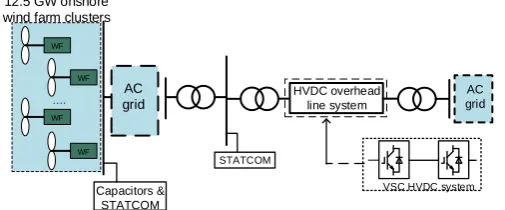
[image:2.595.181.434.201.306.2]This paper will investigate the transmission of island onshore wind power by a 8 GW, ± 800 kV bipolar VSC HVDC system. Considering the fluctuation of the wind power, it is assumed that the installed capacity of this large islanded onshore wind farm clusters is 12.5 GW. The transmission line is an overhead line with a transmission distance of 2,000 km. The system configuration is shown in Figure 1.
Figure 1. Schematic diagram of the system configuration of a large scale islanded onshore wind power transmission via VSC HVDC system.
With the evolution of VSC HVDC technology, the topology of Modular Multi-level Converter (MCC) is now widely used. The VSC HVDC technology studied in this paper will be based on the topology of the popularly used half-bridge MMC. The main technical challenges and corresponding solutions for large scale islanded onshore wind power transmission via VSC HVDC system are discussed below.
The Main Challenges for Large Scale Islanded Onshore Wind Power Transmission via VSC HVDC System
High Rated Current of IGBT
In the early development stage of the VSC HVDC technology, limited by the maximum current of IGBTs, the transmitted power of VSC HVDC system is less than that of LCC HVDC system. However, with the continuous development, the rated voltage and power of the VSC HVDC system are increased and approaching the LCC HVDC system. The VSC HVDC projects with the highest rated voltage and power in the world are emerging in China. In Wudongde hybrid multi-terminal HVDC system, which has been constructed since March 2018, the receiving end in Guangdong is a VSC HVDC of ± 800 kV and 5 GW that is based on MMC topology. It is the highest rated voltage and power of VSC HVDC in the world.
For the studied 8 GW, ± 800 kV VSC HVDC system in this paper, the rated current is 5000 A according to its rated power and voltage. Comparing with the Wudongde project, the required maximum current of IGBT is even higher. This is a big challenge for the existing IGBT technology.
High Voltage Ride through (HVRT) of Wind Turbine Generators (WTG)
The second main challenges for the large scale islanded onshore wind power transmission via VSC HVDC system is HVRT of WTGs. In a wind power HVDC transmission system, the wind turbines are connected to the grid through wind converters. It results in the lack of mechanical inertia in the islanded wind power system. Therefore, the high transient overvoltage could occur at the POC of the wind converter during the AC fault recovery at the sending end of HVDC system or AC fault at the receiving end of HVDC system. Comparing with the conventional equipment, such as transformer, the wind converter is sensitive to the overvoltage. In Chinese national standard [2], it is mentioned that the WTG could disconnect from the grid as soon as the voltage at the POC of the wind converter exceeds 1.2p.u.. The entire power system will collapse due to lack of power if the WTGs are
AC grid
WF WF
WF WF
….
12.5 GW onshore wind farm clusters
Capacitors & STATCOM
AC grid
STATCOM
HVDC overhead line system
disconnected because of the transient overvoltage exceeding the limit. Therefore, how to reduce the transient overvoltage during the fault and fault recovery period is important issues for an islanded wind power HVDC transmission system.
DC Fault
At the early development stage of VSC HVDC technology, the transmission distance is short and the transmission capacity is small. The DC cable is usually used as the transmission line because of its high reliability. However, with the increase of the transmission capacity and the transmission distance, the overhead line DC system is more and more used because of its economic benefit. In Zhangbei four-terminal VSC HVDC system, the overhead line DC system is used. For overhead lines, the failure rate is much higher than that of the cable system. Normally a temporary DC fault might occur due to the lightning strikes or pollution and it requires the fast fault clearing and back to the normal operation.
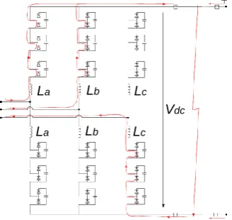
[image:3.595.221.385.347.502.2]In the VSC HVDC system with the popularly used half-bridge MMC topology, the IGBTs of the sub-modules and a reverse diode are connected in parallel. When a DC fault occurs, the IGBT turns off. However, the DC side and the AC side of the HVDC system form a current loop through the reverse diode, as shown in Figure 2. The AC grid can inject a short circuit current into the DC side through this current loop. Consequently, the DC fault cannot be cleared. Therefore, how to quickly clear the DC fault is one of main challenges in a VSC HVDC system based on the half-bridge MMC topology.
Figure 2. MMC operation principle during fault.
The Solutions for Large Scale Islanded Onshore Wind Power Transmission via VSC HVDC System
High Power Semiconductor Devices
With the technology evolution, the press pack IGBT (PPI) is widely used for large capacity VSC HVDC system and HVDC circuit breakers due to its large current capacity, high reliability and suitable for series connection [3]. The current capacity of the PPI could be increased by connecting a plurality of IGBT chips in parallel and a plurality of diode in anti-parallel. At present, the highest power capacity of PPI in the world is 3600 A/4500V [4]. The breakthrough of IGBT current capacity will help the development of large capacity and high voltage VSC HVDC system.
IGCT, as the representative controllable turn-off thyristor, has the advantages of low on-state voltage drop, high voltage level, and large capacity etc.. However, due to its complex drive circuit, it has not been widely used in power systems. With the development of future technologies, the new controllable turn-off semiconductor devices, with the advantages of simple gate drive circuit(as IGBT) and large capacity (as IGCT), are expected to be implemented into large capacity VSC HVDC systems [5].
In the future, with the maturity of silicon carbide technology, it will also become an important direction for the development of high voltage and large capacity VSC HVDC systems.
La Lb Lc
HVRT of WTGs
[image:4.595.191.418.215.297.2]To reduce the transient overvoltage caused by the AC fault in the islanded wind power HVDC transmission system and realize the HVRT of WTGs, the dynamic DC chopper could be installed on the DC side of the MMC inverter to consume extra power, as shown in Figure 3. Under different types of faults, the power need to be consumed at the DC side of the MMC inverter is different. Therefore, the modular chopper circuit could be used. By controlling the number of modules that are put into operation, an effective transient overvoltage reduction could be obtained. According to the existing research results [6], in addition to adding DC chopper, the coordinated control between wind converter and VSC HVDC system should also help to reduce the transient overvoltage in the system.
Figure 3. System topology of VSC HVDC with dynamic braking system.
DC Fault
The universal half-bridge MMC converter cannot block the fault current. According to the existing research results, DC faults of VSC HVDC system are usually cleared by two methods: one is a HVDC circuit breaker, which directly isolates the fault line and stops the fault current; another is a fault self-clearing converter, which stops the fault current by blocking the converter. Then isolates the fault area by a fast isolation switch.
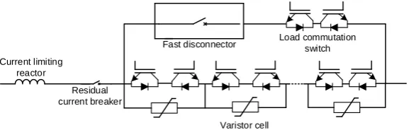
Compared with the AC circuit breakers, the technical difficulty of the HVDC circuit breakers is there is not zero-crossing point in the DC system. Thus, the switch of the circuit breaker must clear the fault under a very high DC short circuit current. The researchers proposed many topologies of the HVDC circuit breaker. From both economic and technical point of view, hybrid HVDC circuit breakers is recommended. As an example, ABB hybrid HVDC circuit breaker [7] topology is shown in Figure 4.
Figure 4. Topology of hybrid DC breaker.
During normal operation, the current flows through the fast mechanical breaker and a load commutation switch of anti-series IGBTs rated to a low voltage. This design results in low on-state losses. In parallel with this is a branch of sub-modules that each contain a varistor. Each sub-module can either bypass or insert its varistor into the current path. An inductor is placed in series with the breaker to limit the rise rate of the fault current. When a fault is detected, the load commutation switch IGBTs are switched off, this commutates the fault current from the main branch into the varistor sub-module branch, allowing the open of the fast disconnector under zero current conditions. With the fault current now in the varistor sub-module branch, the breaker can then control the effective fault impedance by varying the number of varistor sub-modules that are inserted into the fault current path. According to the protection strategy used, the fault current could be eliminated to zero or limited as needed. When the fault current becomes zero, the series circuit breaker is opened and the fault is completely cleared. The overhead lines are used in Zhangbei four-terminal VSC HVDC system and it
WF
WF
WF
WF
Dynamic DC chopper Wind farm
clusters
Rectifier Inverter
DC transmission line
Current limiting reactor
Residual current breaker
Fast disconnector Load commutation switch
[image:4.595.163.452.504.596.2]requires fast clearing of the DC fault. The hybrid HVDC circuit breaker are used in this project [8]. This is the first engineering application of HVDC circuit breaker in the world.
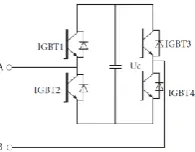
[image:5.595.260.358.246.322.2]Regarding the fault self-clearing converter, many different converter topologies are proposed and they are mainly divided into two categories. The first type of topology cuts off the DC fault arc by providing a back EMF to the fault current path through the capacitors in the arm of sub-modules. Meantime, the reverse series connected diode of the submodule blocks the fault current after the converter is blocked. A typical representation of this topology is the full bridge MMC sub-module (FBSM), whose topology is shown in Figure 5 [9]. In normal operation, IGBT3 is turned off, IGBT4 is turned on, and the operation states of IGBT1 and IGBT2 are the same as those of the half-bridge MMC sub-module. When a DC fault occurs, the power module is blocked and the module capacitor is in a charging state. A back EMF is provided to the fault current path and the DC fault arc is cut off [10].
Figure 5 Topology of full bridge sub module (FBSM)
The second type of topology is to actively block the path of the short circuit current from the AC side to the DC side, e.g. the Alternative Arm Converter (ACC) topology proposed in [11], as shown in Figure 6, the submodules in the AAC could be half bridge or full bridge submodules.
Figure 6. Topology of a AAC with FBSM.
Conclusion
Combining the characteristics of VSC HVDC technology and the islanded wind power system, the main technical challenges and corresponding solutions for large scale islanded onshore wind power transmission via VSC HVDC system are discussed in this paper.
Based on the existing research status and engineering applications, the main technical challenges and corresponding solutions for large scale islanded onshore wind power transmission via VSC HVDC system (±800 kV/8 GW, overhead line system) are as below:
1)High power semiconductor devices
At present, the VSC HVDC valve with highest rated voltage and capacity in the world is ± 800 kV/5 GW, which is under construction in China. No suitable high power semiconductor devices could be used for VSC HVDC system of ± 800 kV/8 GW. The technology of semiconductor devices with higher current capacity needs to be broken.
Sub-module
Directional switch
Arm inductor
[image:5.595.197.410.389.581.2]2)HVRT of WTGs
The DC chopper and coordinated control between the WTG and the VSC HVDC system could effectively help the HVRT of the WTG caused by the AC fault.
3)DC fault
HVDC circuit breakers and the use of fault self-clearing converters are effective solutions for DC fault clearing in the system.
Except for the high power semiconductor devices, which could be used for ±800 kV/8 GW VSC HVDC systems, other technical challenges have been solved in certain level. However, how to find an economical engineering solution is still need to be further studied.
Acknowledgement
This research was financially supported by the Science and Technology Project of Global Energy Interconnection Group Co., Ltd. (Contract No. GEIC-E (2017) 028).
References
[1]J. Bai, S. Xing, D. Jia, et al. Study of Major Questions of Wind Power Digestion and Transmission in China[J]. Power System and Clean Energy. 2010, 26(1): 14–17 (in Chinese).
[2]GB/T 19963–2011, Technical Rule for Connecting Wind Farm to Power System, Dec. 2011 (in Chinese).
[3]D. Zhao and J. Liu, Application Analysis of the Press-pack IGBT in the Power Electronic Field [J]. Power Electronics, 2015, 49(12):46-48 (in Chinese).
[4]G. Liu, Z. Dou, H. Luo, et al. Development of High Power Density 3600A/4500V Press-pack IGBT[C]. Proceeding of the CSEE. 2018, 38(2018): 1–8 (in Chinese).
[5]J. Wen, J. Ge, Y. Pan, et al. Development and Expectation of Power Electronic Devices for DC Grid [J]. Power System Technology, 2016, 40(3):663-669 (in Chinese).
[6] R. Cai, M. Andersson And H. Xie, Methods for Transient AC Overvoltage Reduction at Wind Farm Terminal[C], 2016 China International Conference on Electricity Distribution, Xi’an, China. Aug. 2016.
[7]M. Callavik, A. Blomberg, J. Hafner, et al. The hybrid HVDC breaker: An innovation breakthrough enabling reliable HVDC grids. ABB Grid Systems Technical Papers, 2012.
[8] G. Tang, G. Wang, Z. He, et al. Research on Key Technology and Equipment for Zhangbei 500kV DC Grid [J]. High Voltage Engineering, 2018, 44(7):2097-2106 (in Chinese).
[9] J. Xu and M. M. Bakran. Fault handling Methods and comparison for different DC Breaker topologies and MMC topologies of the HVDC system. Hindawi, Advances in Power Electronics, Volume 2018, Article ID 2719380.
[10]W. Xiang, W. Lin, J. Wen, et al. A New Topology of Sub-modules with DC Fault Current Blocking Capability and a New Type of Hybrid MMC Converter[J]. Proceedings of CSEE. 2014, 34(29): 5171–5179 (in Chinese).