© 2016, IRJET | Impact Factor value: 4.45 | ISO 9001:2008 Certified Journal
| Page 1100
COMPARATIVE STUDY AND DESIGN OF FIXED OFFSHORE DECK
STRUCTURE BY IS-800-2007AND AISC 360-10.
Manjunatha C M
1,Mr. Sathish Kempaiah
2,Mrs. Sahana T S
31
M.Tech student, Department of Civil Engineering, Sri Siddhartha Institute of Technology, Tumakuru, India
2Principal structural engineer, Aker solutions.
3
Assistant Professor, Dept. of civil Engineering, Sri Siddhartha institute of technology, Karnataka, India
---***---Abstract -
The main objective of this presentinvestigation is to understand the Design criteria of two code's considering in the design off shore deck structure, comparing the design consideration's criteria, load factors, material factor's and design strength for two code's. The Deck is considered as fixed base assumption.
In the present study the behavior of superstructure by modeling in the Staad model, modeling of structural element by staad by considering all the elements are steel and they are all coated with corrosion lees paints, all the member's having the same property of Fe 410 grade. The analysis of Structure by in-place analysis using STAAD-Pro-V8i software . Typical design spread sheets developed for the design of Deck members subjected to axial, bending and combined axial & bending loads have been developed for different codes mentioned above and compared with STAAD design results.
The Member strength Utilization Ratios (UCR= actual load/allowable load) is compared for both codes.
Key Words: member strength comparison; load consideration and calculation; modelling and analysis; STAAD Pro V8i; strength comparison; bending moment; comparative results.
1.INTRODUCTION
The offshore plat form is an structure where as to
use to extraction oil and gas from sea bed. In our
India there are few plat form are there because of the
oil exploration is not available in our India's area so
that there is small scale of extraction from few
regions, there are Mumbai high, eastern offshore
vishaka pattana.
The first oil offshore platform in the world is
the Oil Rocks (Neft Daşları), built near Baku in Soviet
Union. Building on the platform began in 1949, with
Soviet Tankers transporting Oil from the first Well to
Baku in 1951.The Oil Rocks lies 45–50 km (about 25
nautical miles) offshore on the Caspian Sea. The most
unique feature of the Oil Rocks is that it is actually a
functional city with a population of about 5000. The
Oil Rocks is a city on the sea, with over 200 km of
streets built on piles of dirt and landfill. Most of the
inhabitants work on shifts; a week on Oil Rocks
followed by a week on the shore. Offshore platforms
are used for exploration of Oil and Gas from under
Seabed and processing. The First Offshore platform
was installed in 1947 off the coast of Louisiana in 6M
depth of water. Today there are over 7,000 offshore
platforms around the world in water depths up to
1,850M.
In general design practice for dynamic loading
assumes the deck frames are fixed at their base. In
reality the supporting on jacket stiffness of the
system .The loads and load cases on deck structure
are considered as per code of off shore construction.
the loads and load cases are considered in design are
same for two codes, The designing as per the two
codes.
1.1 Types of Offshore Plat forms
There two types of offshore plat forms.
a. fixed offshore: In this type there are some types of off shore are there, they are
1. complaint tower
2.jackup plat form
3. concrete gravity
© 2016, IRJET | Impact Factor value: 4.45 | ISO 9001:2008 Certified Journal
| Page 1101
1. tension legged plat forms2. semi sub merged
3.spar platforms
Present study: The complaint (fixed steel) tower's deck is considered for design.
1.2 Methodology
Steps of the structural design;
Typical loads applicable to the design of Industrial structures, such as dead, live, wind ,temperature loads and installation loads are considered. Load combinations as per respective codal stipulations and Industry Practice have been used.
The analysis has been carried out by using STAAD Pro and the results of this analysis are used for the design of the structural members, by using STAAD supported design modules of IS and AISC codes.
The structural analysis is by in-place analysis, and design as per LSD or LRFD method of design
Member strength utilisation ratio (UCR) for axial, bending, combined axial and bending loads have been established by considering design parameters as per applicable code and UCRs for different members are compared.
Typical design spread sheets have been developed for the design of component members subjected to axial (tension/compression), bending and combined axial & bending loads with appropriate load and safety factors as per IS 800:2007 and AISC. These spread sheets have been used to validate the results obtained from STAAD design.
The partial safety factors for loads and materials adopted in different codes for different loading conditions are also be comparing..
1.3 STRUCTURAL IDEALIZATION
The deck structure is placed on four legged jacket, the supports of deck are shown in figure.
The fixed off shore top side deck plat form generally considered as the dimension is 57x38x18m in X-Z-Y Direction the Y portion is up side.
The plat form consist of Drilling deck, Flare tower, Utility process module, Accommodation module, Drilling supports.
The deck structure is the supporting module for the above mentioned components, and the consideration for design is the only deck frame .
The Top side deck plat form stay on the four legged jacket and supports are considered as
fixed. The structure is 40m height from mean see level. The topside consists of six level deck structure namely Cellar deck at EL (+) 40m, Inter mediate deck at EL(+) 48m, weather deck EL(+) 58m. The modelling of structure by the STAAD Pro V8i,and the dimensions are shown in fig 3.2,3.3.
2. Modeling and Design
In the present study, the fixed offshore deck structure is considered for design and modeled in Staad pro software, the deck plat form is 40m above from MSL, and the total height of deck structure is 18 m. The all deck structure is constructed by the steel structures and the all structural elements are having the same grade of steel Fe410,and the columns are all tubular and the al beam members are I sections. the all structural columns and bracings are considered as the fixed. The whole structural components are joined by nodes and welding, the joints are considered as the rigid type of joints. The components on the deck are not modeled in the project and their loads are considered for design, the joints are considered as rigid. The model is being analyzed by in-place analysis in STAAD Pro v8i software.
3.1 material property of steel
Table.3.1. Shows the material property of steel members.
Yield stress ,(fy) 250 N/mm2
Ultimate strength of material,(Fu)
410 N/mm2
Elastic modulus ,(E) 200000.00 N/mm2
Poisson’s ratio,() 0.3
Density, (ρ) 7850 kg/m3
Fig.3.1. shows the height of the deck structure from Men Sea Level (MSL)
© 2016, IRJET | Impact Factor value: 4.45 | ISO 9001:2008 Certified Journal
| Page 1102
Fig.3.3. shows the dimensions support of deckstructure.
Fig.3.4. shows the 3D view of model.
3.2 Load Cases and Combinations Considered in the Design.
Loads on off shore structures: Adequate strength is ensured by defining design loads scenarios and combinations thereof. Design loads include self-weight, operational loads such as Mechanical/ Equipments loads, Piping, Electrical, Instrumentation and Open area live loads as well as environmental loads due to wind, ice or snow.
The top side structures shall be designed to withstand the maximum loads resulting from combination of loads expected during the different phases of the structures life.
a) VERTICAL LOADS
Dead Load
Live Load
Super imposed Dead Load
Machinery Load
Ice and snow loads.b) LATERAL LOADS
Wind load. Load combinationsThe load combination as per the offshore design codes.
a) DL+LL b) Dl+LL+EL
3.3 RESULT AND DISCUSSIONS
A Study of three Dimensional offshore deck frame structure models with IS 8000-2007(LSD) and AISC 360-10(LRFD), with the same loads and load combinations of two codes but design criteria changes as per the two codes and the factors of loads and materials are considered as per the codal provisions. The spread sheet also developed for two codes to validate the staad results. The designed strength of utilization values are compared. The columns are all tubular structures and the beams are all I sections.
3.3.1 The Member strength utilisation ratios results:
The member strength values as per the design of two codes are compared with each other.
Fig: 3.3.1 show the UCR values for the member 208, tubular section Designed for ULS.
0 0.2 0.4 0.6 0.8 1 1.2
1
AISC
IS 800
UCR Value for AISC and IS 800
Member 208
Utili
satio
n
© 2016, IRJET | Impact Factor value: 4.45 | ISO 9001:2008 Certified Journal
| Page 1103
The fig 3.3.1 shows the UCR comparison values [image:4.595.47.560.182.721.2]for the member 208. the member 208 is an rounded tubular structure, it is used as an column, The member design for the Ultimate limit State (ULS).
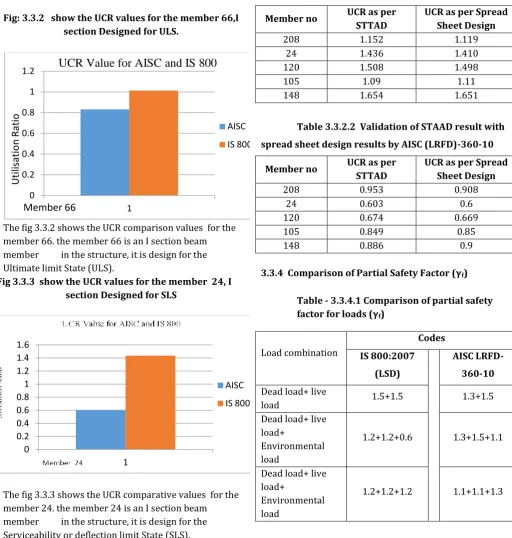
Fig: 3.3.2 show the UCR values for the member 66,I section Designed for ULS.
The fig 3.3.2 shows the UCR comparison values for the member 66. the member 66 is an I section beam member in the structure, it is design for the Ultimate limit State (ULS).
Fig 3.3.3 show the UCR values for the member 24, I section Designed for SLS
The fig 3.3.3 shows the UCR comparative values for the member 24. the member 24 is an I section beam member in the structure, it is design for the Serviceability or deflection limit State (SLS).
3.3.2 Validation of STAAD results with spread sheet design as per codes for both ULS and SLS.
Table 3.3.2.1 Validation of STAAD result with spread sheet design results by IS 800:2007 (LSD)
Member no UCR as per STTAD
UCR as per Spread Sheet Design
208 1.152 1.119
24 1.436 1.410
120 1.508 1.498
105 1.09 1.11
148 1.654 1.651
Table 3.3.2.2 Validation of STAAD result with spread sheet design results by AISC (LRFD)-360-10
Member no UCR as per STTAD
UCR as per Spread Sheet Design
208 0.953 0.908
24 0.603 0.6
120 0.674 0.669
105 0.849 0.85
148 0.886 0.9
[image:4.595.39.568.493.710.2]3.3.4 Comparison of Partial Safety Factor (γf)
Table - 3.3.4.1 Comparison of partial safety factor for loads (γf)
Load combination
Codes IS 800:2007
(LSD)
AISC LRFD-360-10 Dead load+ live
load 1.5+1.5 1.3+1.5
Dead load+ live load+
Environmental load
1.2+1.2+0.6 1.3+1.5+1.1
Dead load+ live load+
Environmental load
1.2+1.2+1.2 1.1+1.1+1.3
0 0.2 0.4 0.6 0.8 1 1.2
1
AISC
IS 800
Utili
satio
n
Ratio
Member 66
UCR Value for AISC and IS 800
0 0.2 0.4 0.6 0.8 1 1.2 1.4 1.6
1
AISC
© 2016, IRJET | Impact Factor value: 4.45 | ISO 9001:2008 Certified Journal
| Page 1104
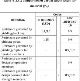
3.3.4 Comparison of Partial Safety Factor for material [image:5.595.31.295.149.414.2](γm)
Table -3.3.4.2 Comparison of partial safety factor for material (γm)
Definition
Codes IS 800:2007
(LSD)
AISC
LRFD-360-10 Resistance governed by
yielding/buckling 1.1/1.1 0.9
Resistance governed by
ultimate stress 1.25 0.9
Resistance governed by yielding/rupture for tension members
- - 0.9/0.9
Resistance governed by design compressive members
- - 0.9
Resistance governed by design flexural/ shear strength members
- - 0.9/0.9
3. CONCLUSIONS
The thesis attempts to study the comparison of the design criteria and member utilization ration for the fixed offshore deck structure by codes IS 800-2007 (LSD) and AISC (LRFD) 360-10. The project aim to find out the difference of two codes design criteria and the economical design procedure for steel design.
a) The member strength utilisation ratios obtained based on Limit State or Load Resistance Factor Design based on two codes IS 800:2007& AISC LRFD (360-10) closely compare with each other. b) Generalley the utilisation ratio obtained from
AISC LRFD (360-10) design are lesser compared to the respective values obtained from IS 800:2007. Refering fig 4.1,4.2,4.3.
c) The dead load factor used in AISC is the lesser from IS 800. The dead load, being a definitive & known load, use of lesser load factor for DL as in AISC can be justified. Refering table 4.3.
d) For combinations considering dead, live & Environmental load, IS code have heigher load factors, whereas AISC adopts lesser load factor for live loads. Thus, the floor beams designed based on AISC for gravity loads will be lessser in size compared to Is code. Refring table 4.3.
e) The codes adopt different load factors for dead load & wind load combinations and AISC adopts a higher load factor for Wind Load. Hence the design of wind sensitive structures based on AISC may govern compared to IS code.
f) The codes generally adopt the same load factors for the service load combinations and, the IS 800 code adopts the lower value of live load factor in dead, liveand environmental load combination. hence, the deflection computed based on all the two codes will be changed.And the deflection limits of two codes having different values. g) STAAD results closely compare with spread sheet
design calcualations for LSD or LRFD designs as per the codes IS 800:2007& AISC LRFD (360-10). Refring table 4.2.1,4.2.2.
h) The AISC method of design is the very economical design compared to is-800.And the comparing structure weight and material property.the AISC code is the better to design.
ACKNOWLEDGEMENT
I am thankful to Mr. Sathish Kempaiah and Mrs. Sahana T S for their guidance. I also thank department of civil engineering SSIT,Tumkur and last but not the least my dear friends who have supported me to complete this work.
REFERENCES
1. D r.N.Nallayarasu, Offshore Structures Analysis and Design, Saipem India Projects Limited, Chennai, during 11-15 December 2006.
2. Dr.N.Nallayarasu, Training course for L&T engineers on offshore structures, L&T Valdel office, Bangalore, during 14 July 2008.
3. IS-800:2007 (2007) ,”Code Practice for Steel Structure” Bureau of Indian Standards, New Delhi, India.
4. BS ISO 19902-2007(LRFD),” Specifican for fixed Steel offshore”.
5. ASCE7 –“Minimum Design Loads for Buildings and Other Structure
6. AISC 360-10 2005,- LRFD Method of design. 7. Arya-Ajmani (1964) “Design of Steel Structures”.
NEM CHAND & BROS; ROORKEE (U.P)
8. BS-5950:2000,“Structural Use of Steel Work in Buildings” Part-1 Code of Practice for Design in Simple and Continous Construction”.
9. S.O. Degertekin (2004) “Design of non-linear semi-rigid steel frames with semi-rigid column bases”. Electronic Journal of Structural Engineering.
© 2016, IRJET | Impact Factor value: 4.45 | ISO 9001:2008 Certified Journal
| Page 1105
11. S.K.Duggal (2010) “Limit State Design of SteelStructure”. Tata McGraw Hill Education Private Limited, New Delhi.
12. IS 875 :1987 (part I to IV ),”Code of Practice for Design of Loads” Bureau of Indian Standards, New Delhi, India.
13. E S Kameshki (1998) “Comparation of BS-5950 and AISC –LRFD Code of Practice”. Journal of Structural Engineering, ASCE, Vol. 3, No 3.
14. L J Morris & D R Plum “Stuctural Steel Work Design to BS 5950”.
15. Prof. Ravindra Bhimarao kulkarni, Vikas Arjun Patil “Comparative Studty of Steel Angles as Tension Members Designed by Working Stress Method and Limit State method”.
16. Dr.Subramanian (2008) “Design of Steel Structures” Oxford University Press, New Delhi. 17. Swapnil B.Kharmale (2007) “Comparative Study