© 2016, IRJET ISO 9001:2008 Certified Journal
Page 36
Confined concrete behavior influencing factors
Esmerald Filaj
1, Agim Seranaj
2, Erdit Leka
31
Department of Building Construction and Transport Infrastructure, Faculty of Civil Engineering, Albania
2Department of Mechanics of Structures, Vice Dean, Faculty of Civil Engineering, Albania
3
Department of Building Construction and Transport Infrastructure, Faculty of Civil Engineering, Albania
---***---Abstract -
Ductility, considered as the ability of the structure or its components to offer resistance in the inelastic domain of response, can be developed only if the constituent material itself is ductile, and this is not the best characteristic concrete has. In order to improve its performance, confinement is recommended. Confinement in concrete is achieved by the suitable placement of transverse reinforcement. This results in a significant increase in the strength and ductility of concrete. Correct interpretation and use of this improved performance of confined concrete, should be based on an appropriate analytic stress - strain model that captures the real behaviour. This paper presents, based on the so know Mander stress - strain model, the influence of different factors on the effectiveness of confinement, such as: the compressive strength of concrete, the amount and the yield strength of transverse reinforcement, the ties spacing, the ties pattern, the longitudinal reinforcement, while interpreting in the theoretical paragraph the importance of the loading rate and the strain gradient. A rectangular reinforced concrete cross - section column is used with reference dimensions very near to the boundaries of what is structurally considered as a “wall”, having a greater possibility of parameters variation. By interpreting in qualitative and quantitative terms the results achieved, the authors conclude that the parameters closely and specifically related with the transverse reinforcement influence the most the behaviour or confined concrete.Key Words: Confined concrete, stress - strain model, confining stresses, concrete strength, ultimate strain, influencing factors
1. INTRODUCTION
Design philosophy is somewhat grandiose term that structural engineers use, meaning the fundamental basis of design [1]. It covers reasons underlying the choice of design loads, and forces, the analytical techniques and design procedures, preferences for a particular structural configuration and materials, but also aims for economic optimization. The importance of a rational design philosophy becomes paramount when seismic considerations dominate design. Nowadays, design philosophy is closely related to the concept of “ductility”. To minimize major damage and ensure the survival of buildings with moderate resistance with respect to lateral forces, structures must be capable of
sustaining a high proportion of their initial strength when a major earthquake imposes large deformations, which may be well beyond the elastic limit. This ability of the structure or its components, or of the materials used, to offer resistance in the inelastic domain of response, is described by the general term “ductility”. It includes, in other terms, the ability to sustain large deformations, and a capacity to absorb energy by hysteretic behaviour. For this reason, it is the single most important property sought by the designer of buildings located in regions of significant seismicity. While the roles of both stiffness and strength, as well as their quantification are well established, the sources, development, quantification and utilization of ductility, to serve best the designer’s intent, are generally less well understood [1]. Ductility in structural members, as pointed, can be developed only if the constituent material itself is ductile, and for sure, due to many known reasons, this is not the best characteristic concrete has. In order to improve its performance, confinement is recommended. Confinement in concrete is achieved by the suitable placement of transverse reinforcement. In principle, at low levels of stress, transverse reinforcement is hardly stressed; the concrete behaves much like unconfined concrete. At stresses close to the uniaxial crushing strength of concrete, high lateral tensile strains develop as a result of the formation and propagation of longitudinal micro cracks. Transverse reinforcement in conjunction with longitudinal reinforcement acts to restrain the lateral expansion of the concrete, enabling higher compression stresses and more important, much higher compression strains to be sustained by the compression zone before failure occurs [1], [2]. This phenomenon, simply, results in a significant increase in the strength and ductility of concrete. Correct interpretation and use of this improved performance of confined concrete, as for any other structural material, should be based, within the technical tolerances accepted by Design Codes, on an appropriate analytic stress - strain model that captures the real (observable) behaviour. The better the stress-strain model, the more reliable is the estimate of strength and deformation behaviour of concrete structural members. There have been many attempts in time from different well known authors to describe maybe a unified one:
© 2016, IRJET ISO 9001:2008 Certified Journal
Page 37
Yong et al. [5] proposed an empirical stress-strain relation of confined high-strength concrete.
Mander et al. [6] proposed a stress-strain relation of confined concrete as a function of the confinement effects depending on various configurations of lateral ties.
Kent and Park [7] developed a stress-strain relation of confined concrete from the stress-strain relation of unconfined concrete.
Park et al. [8] modified the stress-strain relation proposed by Kent and Park [6].
Heo-Soo et al. [9] proposed a stress-strain curve of laterally confined concrete depending on the effects of various parameters.
All of the above listed studies have one thing in common [10]: they accept the complexity of the confinement mechanism - the effectiveness of confinement depends on the compressive strength of concrete, the amount of transverse reinforcement, the yield strength of transverse reinforcement, the ties spacing, the ties pattern, the longitudinal reinforcement, the rate of loading and the strain gradient. The aim of this paper is to study, based on a chosen proposed stress- strain model - more exactly the Mander model - the influence of different factors, most of them listed above, in the confined concrete behaviour. The results will be discussed in qualitative terms more than in quantitative ones, and in the light of Design Codes recommendations.
2. CONFINED CONCRETE STRESS - STRAIN MODEL
Confined concrete stress - strain models are numerous, with certain differences due to certain logical or practical conditions accounted by the authors. This study is based on one of them, perhaps the most known, according to Mander J. B., Priestley M. J. N and Park R. [6], often identified by the name of the first author listed inhere. In the following part of the paragraph, the theoretical background of this model will be discussed, precisely for the rectangular concrete cross sections confined by rectangular hoops with or without cross ties and monotonic loading. This is considered necessary for a better understanding of the confinement mechanism of the results achieved from the study cases and also their comment or interpretation.
2.1 The Basic Equation for Monotonic Compression
Loading
Mander J. B. et al. [6] have proposed in 1984 a unified stress - strain approach for confined concrete, applicable to both circular and rectangular shaped transverse reinforcement. The stress - strain model is illustrated in Fig. 1 and is based on an equation suggested by Popovics. S . For a slow (quasi - static) strain rate and monotonic loading, the longitudinal compressive concrete stress fc is given by:
r c cc c cc
f f’ r /( (r 1 x ))
(1)
cc co1 5 f’ / f’cc co 1
(2)
Fig -1: Stress - Strain model proposed for monotonic loading of Confined and Unconfined Concrete [5]
c c sec
r E / E E
(3)
c co
E 5000 f ’ (MPa)
(4)
sec cc cc
E f’ / (MPa)
(5)
Ec - tangent modulus of elasticity of the concrete (app. value) Esec - secant modulus of elasticity of the concrete (Ec > Esec)
f’cc - compressive strength of confined concrete (see below) f’co - compressive strength of unconfined concrete (Fig. 1)
εco - longitudinal compressive unconfined concrete strain
corresponding to compressive strength f’co (εco= 0.002)
εc - longitudinal compressive concrete strain (as a parameter)
To define the concrete stress - strain behavior of the cover concrete, outside the confined core, the part of the falling branch in the region where is assumed to be a straight line which reaches zero stress at the spalling strain,εsp=0.005 [6].
2.2 Effective Lateral Confining Pressure and the
Confinement Effectiveness Coefficient
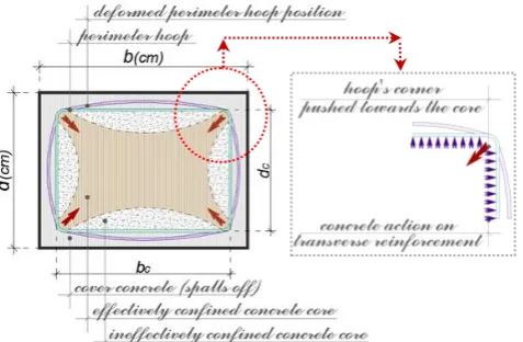
An approach similar to the used by Sheikh and Uzumeri [3] is adopted by the authors [6] to determine the effective lateral confining pressure on the concrete section. The maximum transverse pressure from the confining steel can only be exerted effectively on that part of the concrete core where the confining stress has fully developed due to arching action. Fig. 2 shows the arching action that is assumed to occur between the levels of transverse rectangular hoop reinforcement. Midway between the levels of the transverse reinforcement, the area of ineffectively confined concrete Ai will be the largest and the area of effectively confined concrete core Ae will be the smallest. When using the stress - strain relation, Eq. 1, for computing the confined concrete strength, it is assumed for convenience that the area of the confined concrete is the area of the concrete within the centrelines of the perimeter hoop, Acc. In order to allow for the fact that Ae < Acc, it is considered that the effective lateral confining pressure f’l is a function of the lateral pressure fl modified by the confinement effectiveness coefficient ke:
l e l
f’ k f
(6)
e e cc
[image:2.595.303.565.70.239.2]© 2016, IRJET ISO 9001:2008 Certified Journal
Page 38
cc cc
A Ac (1 )
(8)
fl - lateral pressure from the transverse reinforcement,
assumed to be uniformly distributed over the surface of the concrete core; Ac - area of core of section enclosed by the
centrelines of the perimeter hoop; ρcc - ratio of area of
longitudinal reinforcement to area of core of section. Referring to Fig. 2, the arching action is assumed to act in the form of second - degree parabolas with an initial tangent slope of 45°. Arching occurs vertically between layers of
transverse hoop bars and horizontally between longitudinal bars. The effectively confined area of concrete at hoop level is found by subtracting the area of the parabolas containing the ineffectively confined concrete. For one parabola, the ineffectual area Ai is (w’i)2/6 where w’i is the i-th clear distance between adjacent longitudinal bars. Thus, the total plan area of ineffectually confined concrete core at the level of the hoops when there are n longitudinal bars is:
n 2i i i 1
A w’ / 6
(9)
Incorporating the influence of the ineffective areas in the elevation, the area of effectively confined concrete core at midway between the levels of transverse reinforcement is:
n 2e c c i c c
i 1
A (b d w’ / 6)(1 s’ / 2b )(1 s’ / 2d )
(10)
where bc, dc - core dimensions to centrelines of perimeter hoop in x and y directions, respectively, where bc ≥ dc. The confinement effectiveness coefficient, based on what pointed:
n 2i c c c c
i 1 e
cc
(1 w’ / 6b d )(1 s’ / 2b )(1 s’ / 2d )
k
(1 )
(11)
Typical values of coefficient ke are 0.75 for rectangular column sections, and 0.6 for rectangular wall sections [1]. It is possible for rectangular reinforced concrete members to have different quantities of confining steel in the x and y directions. These may be expressed as:
x sx c y sy c
( A / sd ) ( A / sb )
(12)
Asx - total area of transverse bars running in the x directions Asy - total area of transverse bars running in the y direction The lateral confining stress on the concrete (total transverse bar force divided by vertical area of confined concrete) is given for both directions as:
lx sx c yh x yh
f A / sd f f
(13)
ly sy c yh y yh
f A / sb f f
(14)
At last, the effective lateral confining stresses are defined as:
lx e lx e sx c yh e x yh
f’ k f k A / sd f k f
(15)
ly e ly e sy c yh e y yh
f’ k f k A / sb f k f
(16)
These values are will be used to define the value of compressive strength of confined concrete, according to the chart given in Fig. 3.
Fig -2: Effectively Confined Core for Rectangular Hoop Reinforcement [5]
2.3 Compressive Strength of Confined Concrete
To determine the confined concrete compressive strength f’cc, a constitutive model involving a specified ultimate strength surface for multiaxial compressive stresses is used in this model. The “five - parameter” multiaxial failure surface described by William and Warkne is adopted by the authors since it provides excellent agreement with triaxial test data [6]. The calculated ultimate strength surface based on triaxial tests of Schickert and Winkler is adopted here. Details of the calculations have been given by Elwi and Murray. The general solution of the multiaxial failure criterion in terms of two lateral confining stresses is presented in Fig. 3.
2.4 Ultimate Concrete Compression Strain
[image:3.595.316.550.88.416.2]© 2016, IRJET ISO 9001:2008 Certified Journal
Page 39
Fig -3: Confined Concrete Strength Determination from Lateral Confining Stresses - Rectangular Sections [5] Basing on the curves of Fig. 1, the area under each one of them represents the total strain energy per unit volume required to “fail” the concrete. The increase in strain energy resulting from confinement (shown in shaded) can only be provided by the strain energy capacity of the confining reinforcement as it yields in tension. By equating the ultimate strain energy capacity of the confining reinforcement to the difference in area between the confined and unconfined concrete stress - strain curves, plus additional energy required to maintain yield in the longitudinal steel in compression, the longitudinal concrete compressive strain corresponding to hoop fracture can be calculated. Further details are not important for this study and can be found easily by referring the listed references [6]. A conservative estimate for ultimate compression strain εcu
is given by the following expression [1], and that’s the one used in the numerical examples:
cu 0.004 1.4 fs yh sm/ f’cc
(17)
εsm - steel strain at maximum (peak) tensile stress (Chart. 2) ρs - volumetric ratio of confining steel - for rectangular
sections ρs = ρx + ρy (ρx, ρy defined as per Eq. 12)
Typical values for range from 0.012 to 0.05, a 4- to 16-fold increase over the traditionally assumed value for unconfined concrete.
2.5 Influence of Cyclic Loading on Concrete Stress -
Strain Relationship
Although in this paper the study cases have nothing to do with the loading conditions in a direct way, it is important to specify, even if not in details and qualitatively, the boundaries of validity of the proposed and chosen model. Experiments on unconfined and confined concrete under cyclic loading have shown the monotonic loading stress - strain curve to form an envelope to the cyclic loading stress - strain response [1], [6]. As a consequence, no modification to the stress - strain curve is required when calculating the flexural strength of concrete elements subjected to the stress reversals, typical of seismic loading.
3. CASE STUDY
The case study is based on a reinforced concrete column with a rectangular cross - section and reference dimensions (105cm x 30cm), defined intentionally, quite near to the boundaries of what is structurally considered as a “wall”, having so a greater variation possibility of the parameters in focus - however, it is not important the classification of the structural element according to the Design Codes, (Fig. 4). Concrete, when not defined otherwise, has a characteristic cylinder compressive strength (fck) of 30MPa, and the reference transverse reinforcement is Grade60 according to the American Society for Testing and Materials (ASTM). In any case, the longitudinal reinforcement fulfils the minimum recommended value, and it is distributed in the cross - section according to the basic detailing rules for RC structural members. Concrete confinement is firstly achieved by placement of a perimeter hoop and cross ties φ=10mm, at
10cm of spacing, while considering a 2.5cm of cover. Unconfined and Confined concrete stress - strain curves are those representing the Mander models and its equations [1], [6] (unconfined concrete stress - strain models are discussed by almost the same authors mentioned related to the confined concrete behavior and the differences can be noticed, as it quite happens for the confined concrete, only in the post - peak branch of the curves). Transverse reinforcement stress - strain curves are based on the R. Park model [11]. It must be pointed that the choice of reference materials characteristics, does not affect qualitatively the results of this study or future “similar” ones. The terms “reference”, or “firstly” part of some of the phrases, are used in the sense that the parameters/ factors characterized by them, are study variables.
Fig -4: Reference Rectangular Cross - Section
Three technical elements serve as a judgement foundation: confined concrete compressive strength f’cc, compressive strain εcc corresponding to the compressive strength f’cc , and
the ultimate concrete compressive strain εcu.
3.1 Unconfined Concrete Characteristics Influence
Unconfined concrete characteristics, exactly in this case, the compressive strength f’co and longitudinal corresponding compressive strain εco, are very important indeed, and their
[image:4.595.50.277.103.274.2] [image:4.595.322.538.494.594.2]© 2016, IRJET ISO 9001:2008 Certified Journal
Page 40
Chart -1: Unconfined Concrete Characteristics Influence In fact, the only variable considered inhere is the compressive strength, meaning also the tangent modulus (Eq. 4), while the compressive strain at peak stress is usually considered in the presented value εco=0.002 and the ultimate
compressive strain 2εco can be conservatively adopted [1].
Five different values of compressive strength f’co are considered, assuming unchanged all the parameters related to the section geometry, transverse and longitudinal reinforcement. The results, presented in Chart 1, show that there is an increase in the confined concrete compressive strength f’cc with the increase of the unconfined one, quite proportionally (if a line would be sketched in the chart joining the peak stresses of each of the curves, it would be almost a linear one). The compressive strain corresponding to the compressive strength εcc shifts on the left, decreasing
[image:5.595.34.290.101.260.2]in value and the same happens with the ultimate strain. While the confinement effectiveness coefficient remains constant, the ratios of the lateral confining stresses to the compressive strength, necessary to define according to the model the confined concrete compressive strength basing on Fig. 3, decrease. This tendance, graphically means that the values in the Fig. 3 chart, aim towards the peak, so resulting in lower values of the ratio f’cc/ f’co. Confined concrete
compressive strength has however an increasing law because the direct increase in strength f’co is faster than the
reduction of the ratio f’cc/ f’co. In conclusion, there is an
improvement in terms of strength and a negative escalation in terms of ductility.
Chart -2: Confining Stress Ratios Variation (f’lx/f’co), (f’ly/f’co)
Chart -3: Transverse Reinforcement Grade Influence The strain energy capacity (the surface under each curve - numerically not presented) remains almost constant. So, if no increase in strength is required, than the increase in compressive strength would be unnecessary and with consequences in ductility of the material and structural member in total.
3.2 Transverse Reinforcement Grade Influence
The prime source of ductility of reinforced concrete ele
ments is the ability of reinforcing steel to sustain repeated load cycles to high levels of plastic strain without significant reduction in stress [1]. Behavior is characterized by an initial linearly elastic portion of the stress - strain relationship, with a modulus of elasticity of approximately Es=200GPa, up to the yield stress fy, followed by a yield plateau of variable length and a subsequent region of strain hardening. After maximum stress fu is reached, strain softening occurs, with deformation concentrating at localized weak spot. In terms of structural response, the effective strain at peak stress may be considered the “ultimate” strain, since the effective strain at fracture depends on the gauge length over which measurement is made. Typically, ultimate strain and the length of the yield plateau decrease as the yield strength increases. This trend is, however, not an essential attribute. The desirable characteristics of reinforcing steel are a long yield plateau followed by gradual strain hardening and low variability of actual yield strength from the specified nominal value.
© 2016, IRJET ISO 9001:2008 Certified Journal
Page 41
Chart -5: Confining Reinforcement Bar Diameter Influence At this aim, according Eurocode 2 & 8 [12], [13], only reinforcing steel of Class B or C should be used in reinforced concrete structures, and this principle is also part or other Design Codes like NTC 2008 [14] (only B450C steel). ACI [15] is based on the ASTM classification. Three different steel grades are used according to ASTM A615 [16]:Gr.40, Gr.60, Gr.75 (Chart. 4). Grade 60 reinforcing steel is pleasantly placed referring to what above discussed. The study case is again based on the reference parameters, Eq. 16, Eq. 17 & Eq. 18, and its results are presented in Chart. 4. The unconfined concrete curve attached serves as an “etalon” for a better perception and interpretation of these results. Strength improvement, as expected, are notable for reinforcement grades with high yielding strength. The compressive stress
εcc shifts on the right, which is a good thing. Ultimate
compressive strain values do not follow the same logic as the other two parameters of the curves - the ultimate strain for Grade 60 reinforcement “should have” been between the two other values. This is not a cause of only the reinforcement characteristics, but a combination of factors including the geometry of the section, concrete strength class, transverse reinforcement configuration, etc. So, for other definitions of what above listed, different values might well result. However, no big changes are logically expected. Basing on the model equations, the changes in reinforcement strength cause, while confinement effectiveness coefficient is constant, an increase of the ratios of the lateral confining stresses to the compressive strength, so increased f’cc values.
Chart -6: Confining Reinforcement Spacing Influence
Chart -7: Section Geometry Influence (bc - variation)
Strain energy is also dependent on the factors mentioned above, so no representative conclusion can be achieved.
3.3 Transverse Reinforcement Amount Influence
(variation of the confining reinforcement bar
diameter and the longitudinal hoops space)
In this part of the study, the influence of transverse reinforcement in the confinement mechanism will be discussed in details. Basically, based in the stress - strain model Equations, it was decided to understand how the amount of transverse reinforcement modifies the confined concrete behavior. So, this is in principle the main parameter for the case, keeping every other factor unchanged from the reference values or definitions. There are at least two direct ways to modify this one, that can be applied or not in the same time: by modifying the diameter of the confining reinforcement bars (Chart. 5), or by modifying the space s of the hoops or cross ties referred to
the longitudinal axis of structural element (Chart. 6). Exactly, increasing the confining reinforcement bar diameter, causes the increase on the volumetric ratio of confining steel and according to Eq. 15 and Eq. 16, this results in the increase of effective lateral confining stresses f’lx, f’ly, with almost constant values of the confinement effectiveness coefficient (small differences can be noticed due to the reduction of the clear space between the hoops). Thus, the ratios of the effective lateral confining stresses to
© 2016, IRJET ISO 9001:2008 Certified Journal
Page 42
Chart -9: Hoops Configuration Influence (legs number) the compressive strength, aim towards the bottom - right of the chart in Fig .3, meaning increased strength f’cc values.
Confined concrete ductility and strain energy are very well improved, proportionally with the diameter of the confining bars, thing that can be noticed due to the regular/ similar shape of the stress - strain curves right after the ascending linear - elastic branch. Many of these comments are true for the other case study. Clearly, confinement of the concrete is improved if transverse reinforcement layers are placed relatively close together along the longitudinal axis - there is a positive change of confinement effectiveness coefficient (Eq. 11), and lateral confining stresses (Eq. 13, Eq. 14). However, there will be some critical spacing above which the section midway between the transverse sets will be ineffectively confined, and the assumption of uniform lateral stresses exerted on the concrete core would be inappropriate [1] (meaning that the stress - strain model accepted would be not valid anymore, but more important the confinement mechanism would be quite inexistent). On the other hand, aiming a very close space, especially when overlapping hoops are used, would be inappropriate from a practical point of view. In absolute terms, by comparing both of the cases results, it can be concluded that the variation of the confining bars diameter, influences the most the behavior of confined concrete, in terms of strength, ductility, and strain energy. This conclusion, is somehow specific and should be discussed for other reference conditions in order to take a more representative form, why not adding the economical - technical component also.
Chart -10: Hoops Configuration Influence (hoop vs. cr. ties)
3.4 Section Geometry Influence
The section geometry influences directly the confined concrete behavior (Eq. 9 - Eq. 16). Usually, in a structural point of view, longed shaped columns near the wall definition, are preferred due to their emphasized stiffness related to the strongest axis. In the following part will be discussed in principle if this choice is good enough also related to the ductility concept, especially in the plastic regions of these structural members. At this aim, both of the cross-section dimensions are gradually changed, one by one and not in the same time, in order to see exactly the shape factor (taking as a reference a square section) influence, keeping every other factor unchanged from the reference values or definitions and complying with the Design Codes detailing requirements [13], [14], [15], [16] (the requirements actually define the boundaries of the section parameters to be used in the application because of the initial assumed fixed conditions - Fig. 4). The results presented in Chart. 7 and Chart. 8, demonstrate the same situation: any increase in the cross-section dimensions without increasing the amount of transverse reinforcement, results in a light (depends on the factors defined) of confined concrete compressive strength and ductility (the confinement effectiveness coefficient increases, but the volumetric ratio of confining steel decreases faster, so the effective lateral confining stresses f’lx, f’ly, decrease too). The shape factor influence can be commented in two ways: a) approaching the square section shape by reducing one of the dimensions, the longest one, or b) approaching the square section shape by increasing one of the dimensions, the shortest one. These changes imply the previous conclusion, and should be considered with it. So, no matter the cross-section shape, one should always be careful to have the right amount of transverse reinforcement in order to always aim towards the bottom - right of the chart in Fig. 3, and this should be done in the same time for the both planar directions of the sections.
3.5
Transverse Reinforcement Configuration
Influence (variation of legs number and
hoops/ cross ties configuration)
© 2016, IRJET ISO 9001:2008 Certified Journal
Page 43
Fig -5 & 6: Transverse Reinforcement Configuration Influence (variation of legs number and hoops/ cross ties configuration)
Chart -7: Confinement of concrete with rectangular hoops complying with the Design Codes detailing requirements, with results are presented graphically in Chart. 9 and Chart. 10. Basing on everything pointed in the previous paragraphs and the model equations, it can be with no surprise concluded that the number of legs influence the confined concrete strength, ductility and strain energy - there is an increase in the transverse reinforcement amount, and what follows is interpreted above). To be noticed the effect of the extra middle leg in the longitudinal x - direction.
As mentioned, overlapping hoops improve confined concrete behavior. At first look it might appear that there is no difference between this choice and the use of cross ties, but that’s not true. Overlapping hoops, again, mean increased amount of transverse reinforcement, not in all the section perimeter. The effects might be or not notable, as in previous applications, in function of different factors. For calculations procedures, an average value of the effective legs can be assumed, i.e. for Variant 5: (2x3+2x5+2x7)/ 6 =5, where (2 + 2 + 2) are the spaces between longitudinal bars, 3, 5 and 7 are the effective reinforcement legs in the x - direction. In absolute, the influence of overlapping hoops related to the agreed judgements terms, is greater compared to the case where this configuration is not present (see the top curve of Chart. 9 and 10). For sure, the economical - technical discussion should be as well considered.
3.6 Longitudinal Reinforcement Influence
[image:8.595.310.549.107.263.2]© 2016, IRJET ISO 9001:2008 Certified Journal
Page 44
3. CONCLUSIONS
Basing on the theoretical background, the different numerical applications and corresponding results achieved, their interpretations and discussions, the following conclusions can be made:
Strength and Ductility in structural members is a function of the qualities of the constituent material.
Reinforced concrete members, especially under axial compression forces, may be confined by using transverse steel to improve their strength and ductility.
The confinement mechanism is quite complex & should be understood in details, considering every possible influencing factor, based on a stress - strain model.
Increasing the concrete compressive strength causes a strength increase but ductility/ strain energy reduction.
The desirable characteristics of reinforcing steel are a long yield plateau followed by gradual strain hardening and low variability of actual yield strength from the specified nominal value, for a better ductile behavior.
Section’s geometry does not influence confined concrete behavoir as long as a right volumetric ratio of the confining reinforcement is considered in both directions.
The longitudinal bars should be well distributed around the perimeter of the section, tied across the section, in order to improve the confinement of the concrete.
Transverse reinforcement is the “beating heart” of the confinement mechanism. It is characterized basically by the volumetric ratio, who is a function of: transverse bars diameter, hoops & cross ties spacing and legs number. The greater the volumetric ratio, the greater the improvements in terms of strength and ductility.
REFERENCES
[1] Paulay T., Priestley M. J. N. ”Seismic design of reinforced concrete and masonry buildings”, New York, 1992. [2] Priestley M. J. N. “Myths and fallacies in earthquake
engineering, revisited”, IUSS Press, Pavia, Italy, 2003. [3] Sheikh S. A. and Uzumeri S. M. “Analytical model for
concrete confined in tied”, J. Struct. Div., ASCE 1982; 108(12): 2703-22.
[4] Sheikh S. A. and Yeh Y. Y. “Tied concrete columns under axial load and flexure”, J. Struct. Div., ASCE 1990; 116(10): 2780-800.
[5] Yong Y. K., Nour M. G. and Nawy E. G. “Behaviour of laterally confined concrete high - strength concrete under axial load”, J. Struct. Engin., ASCE 1988; 114(2): 333-51.
[6] Mander J. B., Priestley M. J. N. and Park R. “Theoretical stress-strain model for confined concrete”, J. Struct. Engin., ASCE 1988; 114(8): 1804-26.
[7] Kent D. C., Park R. “Flexural members with confined concrete”, J. Struct. Div., ASCE 1971; 97(7): 1969-90. [8] Park R., Priestley M. J. N. and Gill W. D. “Ductility of
square-confined concrete columns”, J. Struct. Div., ASCE 1982; 108(4): 929-50.
[9] Heo-Soo C., Keun-Hyeok Y., Young-Ho L. & Hee-Chang E. “Stress- strain curve of laterally confined concrete”, Eng. Struct 24, 2002, 1153-1163.
[10] Reddiar M. K. M. “Stress-strain model of unconfined and
confined concrete and stress-block parameters”, Master of Science Thesis, Texas A & M University, U.S.A, 2009.
[11] Computer and Structures Inc., “Technical Notes -
Materials stress - strain curves”, California, 2008.
[12] European Standard, CEN, “Eurocode 2 - Design of concrete
structures, Part 1.1: General Rules - Rules for Buildings”,
Brussels, 2004.
[13] European Standard, CEN, “Eurocode 8 - Design of
structures for earthquake resistance - Part 1: General rules, seismic action and rules for buildings”, Brussels, 2005.
[14] Consiglio Superiore dei Lavori Pubblici, , “NTC 2008 -
Norme Tecniche per le Costruzioni”, Decreto Ministeriale 14 Gennaio 2008, Roma, 2008.
[15] American Concrete Institute, ACI Committee 318, “ACI
318-14 - Building Code Requirements for Structural Concrete and Commentary”, U.S.A, 2014.
[16] American Society for Testing and Materials “ASTM A615 /
![Fig -1: Stress - Strain model proposed for monotonic loading of Confined and Unconfined Concrete [5]](https://thumb-us.123doks.com/thumbv2/123dok_us/8188173.812617/2.595.303.565.70.239/stress-strain-proposed-monotonic-loading-confined-unconfined-concrete.webp)
![Fig -2: Effectively Confined Core for Rectangular Hoop Reinforcement [5]](https://thumb-us.123doks.com/thumbv2/123dok_us/8188173.812617/3.595.316.550.88.416/fig-effectively-confined-core-rectangular-hoop-reinforcement.webp)
![Fig -3: Confined Concrete Strength Determination from Lateral Confining Stresses - Rectangular Sections [5]](https://thumb-us.123doks.com/thumbv2/123dok_us/8188173.812617/4.595.322.538.494.594/confined-concrete-strength-determination-confining-stresses-rectangular-sections.webp)