© 2016, IRJET | Impact Factor value: 4.45 | ISO 9001:2008 Certified Journal
| Page 2310
STUDY OF OUTRIGGER RC FRAME WITH PLAN IRREGULARITIES
SUBJECTED TO SEISMIC LOADING
Raksha M N
1, Shilpa B S
21
Post Graduate Student, Department of Civil Engineering, East West Institute of Technology
2Assistant Professor, Department of Civil Engineering, East West Institute of Technology
---***---Abstract -
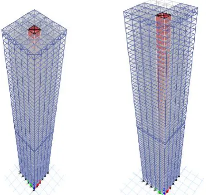
An attempt has been made to study the performance of outrigger system for static approach and dynamic approach for a 60 storey building with plan irregularities and different outrigger materials provided at different location to check the optimum position using software ETABSv2015.Modeling has done for square plan concrete outrigger provided at four different locations with central core in zone 3.results includes lateral displacement, percent reduction and storey stiffness.
Key Words: Outrigger system, Seismic load, Response spectrum, central core, lateral displacement.
1.
INTRODUCTION
The tallest and most primitive structures present on this planet were the pyramids of Egypt made by people on the planet more than 3800 years back. The great pyramid of Giza shaped by ancient people with a height of 146.5m is the first tallest structure ever found. In thirteenth century universes tallest building was dependably a church. Thereafter a new era in the nineteenth century a new form of structures was urbanized in Chicago named skyscrapers using iron/steel as an internal structure. Thereafter in 19th century new epoch switched with innovative form of structures in Chicago termed as skyscrapers with internal structure utilizing iron//steel. So far the world’s tallest building is regarded as Burj Khalifa with 828m (2717 ft) in height. During 19th century trend of tall structures appeared in USA. Now days they are universally scattered notably in countries like JAPAN, KOREA, CHINA AND MALAYSIA.
1.1 Outrigger Structural System
Outrigger structural system encompass of a central core wall either shear wall or braced frames with outrigger truss connecting between core and the peripheral columns. These are the horizontal members designed to control overturning moment and stiffens the building by fastening the core to the exterior column through stiff horizontal members referred as a outrigger member, where as core acts a single-redundant cantilever beam for lateral forces and hence battle the rotation at the top by stretching and shortening action results in tensile and compressive action consequentially restoring couple by combating twisting of core thus cap truss be positioned as a restraining spring at the apex which considerable reduces the lateral deflection
and base moments.
The Victoria office tower (1965) is the first outrigger structural system designed by Nervi and Morerri. These outrigger systems are very popular among tall structures.
1.2 Benefits of outrigger structural system
1.2.1Deformation reduction
© 2016, IRJET | Impact Factor value: 4.45 | ISO 9001:2008 Certified Journal
| Page 2311
Outrigger system provided with belt truss and peripheralcolumns increases the efficiency and also optimal location of outrigger can increase the efficiency of the structure.
1.2.3Foundation forces
Overturning loads can be effectively distributed on foundation by providing outrigger.
2. MODELLING AND ANALYSIS
Modeling process involves 60 storey 6 bays in x direction and 6 bays in y direction with central core of 6×6 are considered.
A. Material properties
Concrete -M30
Steel -Fe 345
Rebar -Fe415
Material type – isotropic
Modulus of elasticity - 5000√fck
B. Section properties
Concrete beam: 450*750 mm
Concrete column: 750*750 mm
Concrete outrigger beam : 350*1000 mm
Steel outrigger beam: shape ISB 200 structural steel
Concrete core shear wall:M30 concrete 300 mm thick
Steel core shear wall: shape ISB 200 structural steel
Belt truss and cap truss: ISB 200 [box section]
Slab: Shell thin membrane 200 mm
C: Load considerations:
For static behavior dead load of the building is considered and live load is taken as 3 KN/m2 and super dead load as 2 KN/m2 ,lateral load confirming IS 1893(part 1)2002 For zone 3: soil type – medium (type 2)
Importance factor (I=1.5) Response reduction factor (R=5)
Time period: Program calculated
Analysis is done for different location of outrigger and belt truss then results are tabulated and graphs are plotted for different parameters chosen.
Case 1: Square plan: Structure without outrigger Concrete outrigger
Structure with outrigger at 60
Structure with outrigger at 60 and 45
Structure with outrigger at 60 and 30
Structure with outrigger at 60 and 15 Steel outrigger
Structure with outrigger at 60
Structure with outrigger at 60 and 45
Structure with outrigger at 60 and 30
Structure with outrigger at 60 and 15 Case 2: L Shape plan:
Concrete outrigger
Structure with outrigger at 60
Structure with outrigger at 60 and 45
Structure with outrigger at 60 and 30
Structure with outrigger at 60 and 15 Steel outrigger
Structure with outrigger at 60
Structure with outrigger at 60 and 45
Structure with outrigger at 60 and 30
Structure with outrigger at 60 and 15
[image:2.595.335.542.527.722.2]
© 2016, IRJET | Impact Factor value: 4.45 | ISO 9001:2008 Certified Journal
| Page 2312
3. RESULTS AND DISCUSSION
Chart 1: Comparison of concrete and steel outrigger
for square shape RC frame building
Discussion:
From graphical representation square frame with
concrete outrigger shows significant reduction of
lateral displacement compared to structure provided
with steel outrigger, also it is represented in the table
below.
Chart 2: Comparison of concrete and steel outrigger
for L shape RC frame building in X direction and Y
direction.
Discussion:
From graphical representation concrete outrigger
provides more stiffness to the structure when
compared to steel outrigger.
Chart 3: Storey stiffness for square outrigger
© 2016, IRJET | Impact Factor value: 4.45 | ISO 9001:2008 Certified Journal
| Page 2313
Discussion:
From graphs it can be observed that structure without
outrigger is less stiff than structure with outriggers.
Concrete outrigger shows better stiffness than steel
outrigger
.
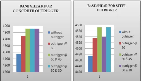
Chart 5: Base shear for square plan building
Chart 6: Base shear for L shape plan building
Discussion:
Base shear mainly depends on the weight of the
structure .it is the estimation of total horizontal load
period the stiffness of the structure increases.
Table 1: Lateral displacement and percent reduction for both concrete and steel outrigger tabulated separately with square plan.
SQUARE CONCRETE OUTRIGGER
SL NO
OUTRIGGER LOCATION
MAXI DISPLACEME NT EQX
% REDUCT ION
MAXI DISPLACEME NT EQY
% REDUCT ION
1 WITHOUT
OUTRIGGETR 244.5 244.5
2 OUTRIGGER AT 60
225 7.98 225 7.98
3 OUTRIGGER AT 60 AND 45 222.9 8.83 222.9 8.83
4 OUTRIGGER AT 60 AND 30 218.7 10.55 218.7 10.55
5 OUTRIGGER AT 60 AND 15 218.1 10.79 218.1 10.79
SQUARE STEEL OUTRIGGER
SL
NO OUTRIGGER LOCATION
MAXI DISPLACEME NT EQX
% REDUCT ION
MAXI DISPLACEME NT EQY
% REDUCT ION
1 WITHOUT
OUTRIGGETR 244.5 244.5
2 OUTRIGGER AT 60
241 1.43 241 1.43
3 OUTRIGGER AT 60 AND 45 239 2.25 239 2.25
4 OUTRIGGER AT 60 AND 30 237.9 2.70 237.9 2.70
5 OUTRIGGER AT 60 AND 15 237.6 2.82 237.6 2.82
Table 2: Lateral displacement and percent reduction for both concrete and steel outrigger tabulated separately with L Shape plan
L SHAPE OUTRIGGER
SL
NO OUTRIGGER LOCATION
MAXI DISPLACEME NT EQX
% REDUCT ION
MAXI DISPLACEME NT EQY
% REDUCT ION
1 WITHOUT
OUTRIGGETR 282.4 268.9
2 OUTRIGGER AT 60
243.5 13.77 226.7 15.69
3 OUTRIGGER AT 60 AND 45 240.4 14.87 222.6 17.218
[image:4.595.37.282.376.515.2] [image:4.595.37.272.554.684.2]© 2016, IRJET | Impact Factor value: 4.45 | ISO 9001:2008 Certified Journal
| Page 2314
5 OUTRIGGER AT 60 AND 15 235.5 16.6 217.7 19.04
L SHAPE STEEL OUTRIGGER
SL NO
OUTRIGGER LOCATION
MAXI DISPLACEME NT EQX
% REDUCT ION
MAXI DISPLACEME NT EQY
% REDUCT ION
1 WITHOUT
OUTRIGGETR 244.5 244.5
2 OUTRIGGER AT 60
225 7.98 225 7.98
3 OUTRIGGER AT 60 AND 45 222.9 8.83 222.9 8.83
4 OUTRIGGER AT 60 AND 30 218.7 10.55 218.7 10.55
5 OUTRIGGER AT 60 AND 15 218.1 10.79 218.1 10.79
4. CONCLUSIONS
By introducing outrigger structural system in tall
building flexibility of the structure is reduced and
stiffness increases that makes the structure efficient
under lateral load.
Structure provided with outrigger and belt truss
structural system shows significant variation in
lateral displacement for L Shaped structure with
reduction of 19.41% in Y direction provided with
concrete outrigger at the mid height of the structure
than the steel outrigger hence it can be concluded
that L Shape is the suitable for seismic zone 3.
Modal investigation is carried to catch the time
period of the structure significant vibrations and
high flexibility is seen in the structure without
outrigger when compared to other models.
ACKNOWLEDGEMENT
I would like to thank my guide, head of the department, principal, friends and family and all other who helped me in completing this thesis.
REFERENCES
[1] Outrigger system design consideration by Hi Sun Choi
and leonard joseph in 2012.
[2] Behavior of outrigger structural system for high rise
building Alpana L. Gawate and Bhusari in 2015.
[3] Structural system selection and highlights
ctbuh.org/papers.
[4] A performance based study on static and dynamic
behaviour of outrigger structural system for tall buildings.
Prateek N. Biradar, Mallikarjun S. Bhandiwad.
[5] Analysis of outrigger system for tall vertical irregularities
structures subjected to lateral loads Karthik .N. M,
N.Jayaramappa.
[6] A Study on Static and Dynamic Behavior of Outrigger
Structural System for Tall Buildings by Kiran Kamath, N.