Design & Development of TIG Welding – Special
Purpose Machine
Mayur Takalkar1, Vikash Kakarparthy2, Ibraheem Raza Khan3
1, 2, 3
Mechanical Engineering, Indira College of Engineering & Management
Abstract: The paper deals mainly with the designing of mechanism, which is able to weld the Vibratory bowl feeder made up of sheet metal in a spiral motion with an improved degree of fineness which is relatively less cumbersome than traditional welding process. The technical constraint that has been taken into consideration while designing and developing the mechanism was to achieve the stability, linear and uniform speed of welding torch and uniform weld thickness for a quality product. The details of testing on various silencer shells is given in the paper. In the near future, variable frequency drive (VFD) can be installed for its full automation.
Keywords:TIG Welding, Gas Tungsten Arc Welding, Bowl Fedder Welding, Timing Pulley, Automated Welding
I. INTRODUCTION
Adapting to automation has taken pace and so has adaptation to automatic machines. Despite the losses in old and conventional methods of manufacturing and hazards associated with them, small-scale industries do not prefer automated machines or special purpose machines for a specific work. A significant part of the work in the production is particularly dependant on human labour. Even with the advancement in automation and the availability of cutting edge technology, human labour is regrettably involved in the process instead of the machine, as in many cases it is too expensive for small-scale industries. It is the need of the hour to enhance the existing machinery by automating them to get more benefits with minimal cost inputs. In this paper a similar effort has been put forth to further compliment this need for low cost automation. Considering a TIG welding SPM for any axi-symmetric object and in this case a Vibratory bowl feeder as a case study, study has been done to fulfill the needs for automation in this area. This creates the need for an indigenously made automatic TIG welding mechanism which would minimise direct exposure of welder to hazardous fumes and bright light of arc. Also minimise the time consumption for TIG welding, thus overcoming the drawbacks in the present manual welding process.
When the TIG welding process is carried out manually, the production rate achieved is less & due to the non-uniformity in the motion of the weld gun, the accuracy and quality of welding gets hampered. However, in case of this mechanism, the motion remains uniform during welding & it helps to avoid the pits and bulge formations due to the variation in the movement of welder's hand.
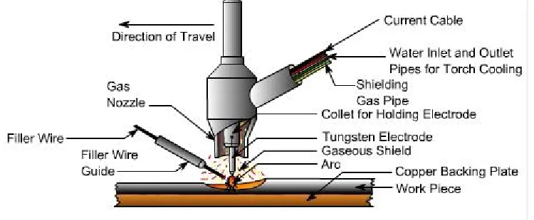
[image:2.612.125.500.566.721.2]TIG welding (Tungsten inert gas welding) is also called as Gas Tungsten Arc Welding (GTAW) uses a non-consumable electrode and a separate filler metal with an inert shielding gas.[1] This is the term used by welding engineers on blueprints and in welding procedures. The TIG was introduced around the 1940’s; it used to be referred to as “HeliArc” because the shielding gas used was helium.[2] It is no longer called HeliArc because in most cases the shielding gas used is Argon.
II. NEED
A. Productivity
Demand for a bowl feeder in the material handling business being high, the manufacturing of the same when done entirely manually, takes a significant amount of time. Hence to suffice the over rising demand, one has to have a long-term solution.
B. 3rd Dimension
It is quite easy to weld a 2D cylinder/circle. As complex as the shape gets, the process of welding of this very complex object becomes more difficult.. Welding of a Spiral path, particularly in this case study needs to be carried out in 3Dimensions, i.e. circumferentially and about its longer axis too. Achieving this motion is the most challenging part and this study further exhibits a probable way out to this particular challenge.
C. Human Errors
Due to the inferior or varying adroitness of the weld gun operator, unforeseen and expected errors occur further leading to improper weld quality and the decrease in strength of the joint.
D. Problems Faced by Welder :
These are some genuine problems faced by a worker practising TIG Welding. Taking spiral nature of the bowl feeder into consideration, the weld gun operator has to rotate the bowl for every 90-degree arc.
E. Fatigue is caused due to poor ergonomics.
Prolonged exposure to sparks causes strain to the eyes of the weld gun operator and over a period of time he develops poor eyesight and bad visibility. If the spark as a result of the welding enters the weld gun operator’s eyes, its after-effect usually lasts for 3-4 days. Moreover, when the argon gas is inhaled, it causes constipation.
F. Adverse effect on Health of welding gun operator due to amount of Tungsten fumes produced in welding process; 1) Non -Uniformity of the weld due to shaking or slight shiver in the hand of the while moving of torch
2) Safety of the operator
3) The available SPM in the market is very costly, small-scale industries cannot afford this SPM.
III.METHODOLOGY
The methodology adopted in the completion of the project is as described below: 1) Exploration of work processes at the case study’s location
2) The identification of the problem.
3) Searching for solutions to increase the productivity of vibratory bowl feeder. 4) Finding out concepts to fulfil the purpose.
5) Selection of drilling machine mechanism from available solutions. 6) Proving the path traced by machine using a prototype
7) Design of actual machine components 8) Manufacturing of actual machine components 9) Assembling and testing of machine
10) Scrutinizing the motion to achieve the desired result
IV. MECHANISM
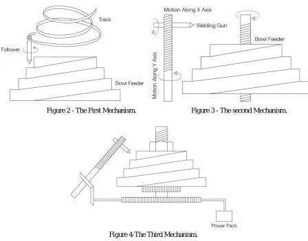
Figure 2 - The First Mechanism. Figure 3 - The second Mechanism.
Figure 4-The Third Mechanism.
A. New Updated Drawing Of The Final Mechnism
These mechanisms were put to test and after rigorous brainstorming and reviewing the drilling machine mechanism emerged as the best suited mechanism for this case study. In this mechanism, the operation of drilling involves three motion simultaneously, one linear and and two rotational. So it was understood that the spiral profile of the bowl feeder which was 3-Dimensional could be traced with the help of this mechanism.
[image:4.612.116.498.581.718.2]To achieve the 3-Dimensional path, the drilling machine mechanism was used in an inverted position unlike the conventional method. The main objective was to obtain rotational motion and at the same time vertically up and down motion of bowl feeder which was achieved with the help of the rack-pinion and axle assembly. This particular assembly ensured that the rotational motion is obtained as well as linear motion along the axle.So with the help of this combination, the bowl feeder could be rotated and whilst rotation it can be traversed axially as well, thus making it possible to trace the 3 dimensional spiral path. the cad model of the finished SPM is shown in the figure below
V. DESIGNED AND MANUFACTURED COMPONENTS DETAILS
COMPON
ENT Cad Model Manufactured Component Specification
Bowl Feeder
Stub Diameter:290mm Height:180mm
Thickness of the sheet:2.5mm Length of strip:1000mm
Timing Pulley Assembly
Gear ratio: 4:1
Pulley: OD 127.2 mm, no of teeth 80
Pinion: pitch 6.64mm Belt: width 25mm, centre dist 450 mm
Rack and Axle Assembly
Rack: En8, OD 50mm,pitch 6.64mm, depth 4.7mm Axle: En8, OD 25mm, L 670.2 mm
Stepper Motor and Pinion Assembly
Force acting on shaft (F) :200 N
Radius of pinion (R) : 15 mm Torque required :-
T = F * R = 200 * 15 T = 3000 N-mm = 3 N-m Stepper motor with 5 N-m is selected
VI.CALCULATIONS
A. Calculations for buckling of axle By EULER’S Formula,
σc x A > π2 x E x I ÷ Leq2 where,
σc = permissible stress , N/mm2 A = Area of cross section , mm2 E = modulous of elasticity, N/mm2 I = momoent of inertia , mm4 Leq = equivalent length , mm σc x A > π2 x E x I ÷ Leq2
15 x 9.81 x π/4 x d2 > π2 x 2 x 105 x π/64 x d4 ÷ (680/2)2 d = 11.74 mm =12 mm
hence,
diameter is taken as 20 mm , where,
factor of safety = 20 / 12 FOS= 1.666.
B. Axial loading σ= F ÷ A where ,
σ= normal stress , N/mm2
F= axil force / load on member , N A = cross section area , mm2 σ= 15 x 9.81 ÷ π/4 x (20)2
σ=0 .468392 , N/mm2
Factor of safety, FOS= Sut ÷ syt FOS= 370 ÷ .468392 FOS= 789 .
Hence, the component is safe for axial loading.
C. Timing Pulley Belt :
The length of the belt can be calculated as
lb = (dm x π / 2) + (df x π / 2) + (2 x lfm) + ((df - dm)2 / (4 lfm)) where
lb = length of belt mm,
df = bigger pulley diameter , mm dm = motor pulley diameter, mm π = 3.14.
lfm = center to center distance of pulleys ,mm The length of the belt can be calculated as
lb = (31.8 x π / 2) + (127.2 x π / 2) + (2 x 200) + ((127.2- 31.8)2 / (4 x 200)) lb = 661.133 ,mm.
hence , the standard belt of length 660 mm was selected.
D. Speed Ratio
SR = nf / ns Where ,
SR = speed ratio
nf = revolutions per minute - fastest machine ns = revolutions per minute - slowest machine SR = nf / ns= 2 / 0.5
SR = 4 .
E. Calculations for pinion Γ = T x R / J
Γ = shear stress , N/mm2
R = distance of outer most fibre from neutral axis , mm T = torque , N-mm
J = polar moment of inertia , mm4 Γ = T x R / J
Γ = 35 x 9.81x 10 x 10 ÷ π/32 x (20)4
Γ = 2.185833 , N/mm2
factor of safety , FOS= Ssy ÷ Γ
FOS= 0.577 x 370 ÷ 2.185833 FOS= 94.285.
Hence , the component is safe for shear loading.
F. Selection of stepper motor Force acting on shaft (F) = 200 N Radius of pinion (R) = 15 mm Torque required to grinding:- T = F * R = 200 * 15 T = 3000 N-mm = 3 N-m
Stepper motor with 5 N-m is selected Fos = 5 / 3 =1.666
Required factor of safety is 1.66
VII. RESULTS
A. Productivity/ time reduction
The main objective of the case study was to increase productivity i.e. to decrease the time required for welding a whole bowl feeder. Thus according to a detailed observations the results are as follows:
Manual
welding(min)
Welding with
SPM (min)
Percent
Reduction
99
20
80%
92
19
80%
108
23
79%
102
18
82%
106
22
79%
105
20
81%
Graph 1: Manual Welding vs Welding with SPM
B. Analysing the results, 80% Reduction in time of weld is achieved.
Apart from this, Qualitative Results regarding Human safety, Human effort, Weld finish, Grinding are also Contributing enormously which is leading to increasing in productivity.
VIII. COSTING
Wherever possible, the components were machined, manufactured and fabricated in-house and purchased. The overall costing of the SPM is as follows :
Table 1: Cost of Elements
IX.CONCLUSION
Thus a solution to the problem has been successfully found which led to the design of a machine that can trace any 3-D profile. Moreover, a special purpose machine has been developed which will able to weld any complex axi-symmetric component just by adjusting the design parameters with respect to the given component.
The SPM for TIG Welding of bowl feeder has been designed successfully using the concept of drilling machine. Achieving primary requirements of scrutinizing motion and increasing productivity have been meet to a higher extent. It has become possible for any unskilled individual to carry out the welding using the SPM. Elimination of manual errors and Welder himself from the scenario has benefited the operator from harmful argon gas causing ill effects and increasing quality of weld.
0 20 40 60 80 100 120
1 2 3 4 5 6 7
M
in
u
te
s
Manual welding(min)
Welding with SPM (min)
Elements Cost in INR
Purchased Components 31,544
Machined Components 16,545
In-House Fabricated Parts 7,650
Machining Cost 3,470
Hence, manufacturing Special Purpose Machine for TIG welding of vibratory Bowl Feeder has been an eminent solution to the prefaced problem statement considering the scope of project.
X. BIBLIOGRAPHY
[1] R. W.Ttulankar, "Automation in TIG Welding process," International Journal of Engineering Trends and Technology., p. 6, 2013.