5
IX
September 2017
Overall Control Strategy of Grid Connected to
Wind Farm Using FACTS
Rohit Kumar Sahu1, Mr. Ashutosh Mishra2 1, 2
E.E.E Department, RSR-RCET, Bhilai, Chhattisgarh, INDIA
Abstract: Voltage Stability is a key factor for the stable operation of grid connected to wind farm during fault through and grid disturbances. This paper considers the impacts of the Static VAR Compensator (SVC) and Static Synchronous Compensator (STATCOM) on stability of the wind farms based on fixed speed induction generators (FSIG) which are connected to power system, after a severe disturbance occurrence. Because of asynchronous characteristic of fixed speed induction generators, the instability in wind farms based on FSIG is severally created by the extreme reactive power absorption by FISG after fault. This phenomenon is a result of rotor slip of FISG increase during the fault, and consequently, the consumption of reactive power is raised. The comparison is made between the performances of the wind farm equipped by SVC and STATCOM to improve the wind farm stability during and
after fault. The simulation results show both of the devices can enhance the system stability during and after disturbance, especially when the network is weak. It is shown that the STATCOM have a much better performance as compared to SVC to improve wind farm stability, and provided better reactive power support to network.
Keywords: Fixed Speed Induction Generator (FSIG), Power System Stability, FACTs, STATCOM, SVC.
I. INTRODUCTION
Energy consumption increases gradually due to the rapid advance in the industrial sectors; also the deficit in fossil fuel and increased energy demand turned the world's attention towards the renewable energy resources. Renewable Energy is one of the alternative sources of energy that has become very important and relevant at present day. Renewable energy can be used without using fossil fuels and can be renewed and sustained but were as it is not possible through non-renewable energy. They are being used in agriculture, industry and social service sector. Therefore renewable energy has positive effect on the environment and human life [1]. The wind power penetration has increased dramatically in the past few years; hence it has become necessary to address problems associated with maintaining a stable electric power system that contains different sources of energy including hydro, thermal, coal, nuclear, wind, and solar. In the past, the total installed wind power capacity was a small fraction of the power system and continuous connection of the wind farm to the grid was not a major concern. With an increasing share derived from wind power sources, continuous connection of wind farms to the system has played an increasing role in enabling uninterrupted power supply to the load, even in the case of minor disturbances.
Voltage stability and an efficient fault ride through capability are the basic requirements for higher penetration. Wind turbines have to be able to continue uninterrupted operation under transient voltage conditions to be in accordance with the grid codes [2]. Grid codes are certain standards set by regulating agencies. Wind power systems should meet these requirements for interconnection to the grid. Different grid code standards are established by different regulating bodies, but Nordic grid codes are becoming increasingly popular [3]. One of the major issues concerning a wind farm interconnection to a power grid concerns its dynamic stability on the power system [4]. Voltage instability problems occur in a power system that is not able to meet the reactive power demand during faults and heavy loading conditions. Stand alone systems are easier to model, analyze, and control than large power systems in simulation studies. A wind farm is usually spread over a wide area and has many wind generators, which produce different amounts of power as they are exposed to different wind patterns.
II. OUTLINE OF FACTS DEVICES
A. Statcom
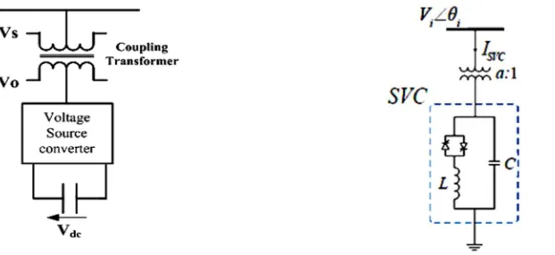
The STATCOM can provide dynamic reactive power compensation to provide voltage stability during and after fault. This prevents from acceleration of rotor by enhancing the electric torque generated by the FSIG, and finally improves the system stability. The operation of the STATCOM is based on voltage source convertor technology or current source convertor technology. STATCOM can control capacitive or inductive current independent of bus voltage. The voltage source convertor (VSC) and coupling transformer are two main sections in STATCOM as shown in Fig.1. Voltage source converter generates synchronous voltage of fundamental frequency and controllable magnitude and pitch angle. The STATCOM can be operated in following two different modes: (i) Inductive mode (ii) Capacitive mode.
In Capacitive mode, the voltage of convertor is upon the transmission line and the STATCOM is considered as a capacitive reactance and current direction is from STATCOM towards the system. In inductive mode, the system voltage is upon the convertor voltage and the STATCOM is considered as inductive reactance and current direction is towards STATCOM from the system.
B. SVC
SVC is a static VAR compensator that is connected in parallel to the transmission line. SVC acts as a generator/load, whose output is adjusted to change capacitive or inductive with a view to hold or control specific energy device variables. Static VAR systems are carried out with the aid of utilities in transmission packages for several functions. The primary cause is generally for speedy control of voltage at weak points in a network. Installations can be at the midpoint of transmission interconnections or at the road ends. SVC is much like a synchronous condenser but without rotating element in that it's far used to supply or absorb reactive power. The basic shape of SVC is shown in Fig.2.
[image:3.612.167.478.388.531.2]The SVC is hooked up to a coupling transformer this is connected directly to the AC bus whose voltage is to be regulated. SVC consists of a controllable shunt reactor and shunt capacitor(s). Overall susceptance of SVC may be managed by using controlling the firing perspective of thyristors. However, the SVC acts like fixed capacitor or fixed inductor on the most and minimum limits.
Figure 1: A functional model of a STATCOM Figure 2: Basic structure of SVC
III. SIMULATED SYSTEM
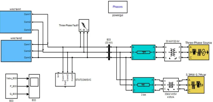
Single line diagram of a typical fixed speed wind power plant under study is shown in Fig.3. The simulation model is carried out using the MATLAB SimPowerSystems toolbox. A power system model of wind farm distribution network is shown in Fig.4. The system consists of a 220 KV, 50-Hz, sub transmission system, feeds a 33 KV distribution system through 220 kV/33 V step down transformer. A test system consisting of two wind farm of 9 MW (each 4.5 MW) and each wind farm having three equal capacity (1.5 MW) wind turbine induction generators (WTIGs) are connected to the 33 KV distribution system, exports power to 220 KV grid through a 25 km transmission line and a load have been connected to the network.
220 kV Grid 33/ 220 kV
Transformer
25 km transmission line
STATCOM/ SVC Wind Farm 1
Wind Farm 2
[image:4.612.168.468.79.176.2]PCC
Figure 3: Single line diagram of the studied system
Figure 4: Simulation model of Wind Farm distribution network
IV. SIMULATION RESULTS AND DISCUSSIONS
The test system is studied at steady state condition and fault state condition. At the fault state, the voltage, active power and reactive power are monitored at the main bus B33. The behavior of the wind power plant is recorded during fault events and after fault clearance. The studied wind farm operates at the nominal wind speed of 11 m/s, so the wind turbines operate at nominal values. During fault period, it can be assumed that the wind speed does not change. The dynamic performance of WTIG for the constant wind speed is analyzed for different cases which are (i) without Fault and without FACTS device (ii) without fault and with FACTS device (iii) with fault and without FACTS device (iv) with fault and with FACTS device.
A. Case 1: Without Fault and Without FACTS Devices
The generated active power, reactive power, voltage at point of common coupling without using FACTS devices (normal case) is shown in Fig.5. As seen from these figures the voltage at point of common coupling approaches 0.9831 p.u. and the generated active power injected from the wind farm is nearly 8.6234 MW but the reactive power at PCC reaches approximately 1.3547 MVAR. In order to support the voltage and provide reactive power compensation at PCC, STATCOOM and SVC should be connected at PCC. Therefore, simulations are carried out with STATCOM and with SVC. It should be noted that the two kinds of FACTS devices in this study give the same performance in healthy conditions.
B. Case 2: Without Fault and With FACTS Devices
[image:4.612.133.504.219.397.2]voltage stability at point of common coupling. The voltage reaches approximately 0.9980 p.u while it was 0.9831 p.u before adding them to the system. STATCOM and SVC have efficiently supported the system voltage stability. It should be noted that STATCOM has less oscillation than SVC in improving the voltage stability.
C. Case 3: With Fault and Without FACTS Devices
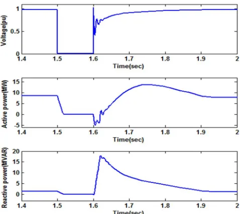
[image:5.612.73.559.113.373.2]A three phase to ground fault (LLLG) was simulated at PCC in this study. As seen from Fig. 7, the voltage before the occurrence of the fault was 0.9831 p.u (pre-fault value) but after the LLLG fault occurred, the voltage dipped down to zero at t=1.5s then at t=1.6s the fault is cleared and the voltage gets back to its pre-fault value. The reactive power at PCC without the integration of FACTS devices can be seen in Fig. 7. It can be observed at PCC that the reactive power increases after the disturbance to 17.9 p.u and gets back to its pre-fault value after sometime. The active power at PCC without the integration of FACTS devices can be seen in Fig. 7. It can be observed at PCC that the active power decreases after the disturbance to 0 p.u and gets back to its pre-fault value after sometime.
Figure 7: Variations of the voltage, active power, and total absorbed reactive power without using STATCOM/SVC with Fault Figure 5: Variations of the voltage, active power,
and total absorbed reactive power without using STATCOM/SVC
Figure 6: Variations of the voltage, active power, and total absorbed reactive power with using
[image:5.612.192.431.503.716.2]D. Case 4: With Fault and With FACTS Devices
Different types of faults (LG, LLG, LLG, LL and LLL) were simulated at PCC in this study. Improving the transient stability margin of the grid can be obtained by the utilization of the given two FACT devices (STATCOM, SVC). In order to compare the performance of these two FACT devices, three parameters were monitored during these two disturbances. These parameters are the voltage, active power and reactive power at PCC.
1) With LG Fault: In Fig. 8 it is clearly shown that after the fault recovery, the voltage at PCC gets back to the pre-fault value. In maintaining voltage stability point of view or the voltage recovery time, it is also worth noting that the action of STATCOM is better than the action of SVC for the LG fault. The response is faster in STATCOM than SVC.
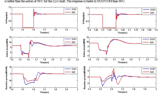
2) With LLG Fault: In Fig. 9 it is clearly shown that after the fault recovery, the voltage at PCC gets back to the pre-fault value. In maintaining voltage stability point of view or the voltage recovery time, it is also worth noting that the action of STATCOM is better than the action of SVC for the LLG fault. The response is faster in STATCOM than SVC.
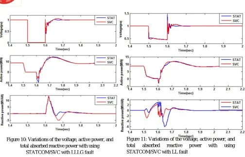
3) With LLLG Fault: In Fig.10 it is clearly shown that after the fault recovery, the voltage at PCC gets back to the pre-fault value. In maintaining voltage stability point of view or the voltage recovery time, it is also worth noting that the action of STATCOM is better than the action of SVC for the LLLG fault. The response is faster in STATCOM than SVC.
[image:6.612.47.567.211.523.2]4) With LL Fault: In Fig.11 it is clearly shown that after the fault recovery, the voltage at PCC gets back to the pre-fault value. In maintaining voltage stability point of view or the voltage recovery time, it is also worth noting that the action of STATCOM is better than the action of SVC for the LL fault. The response is faster in STATCOM than SVC.
Figure 8: Variations of the voltage, active power, and total absorbed reactive power with using
STATCOM/SVC with LG fault
Figure 9: Variations of the voltage, active power, and total absorbed reactive power with using
5) With LLL Fault: In Fig.12 it is clearly shown that after the fault recovery, the voltage at PCC gets back to the pre-fault value. In maintaining voltage stability point of view or the voltage recovery time, it is also worth noting that the action of STATCOM is better than the action of SVC for the LLL fault. The response is faster in STATCOM than SVC.
Figure 12: Variations of the voltage, active power, and total absorbed reactive power with using STATCOM/SVC with LLL fault Figure 10: Variations of the voltage, active power, and
total absorbed reactive power with using STATCOM/SVC with LLLG fault
Figure 11: Variations of the voltage, active power, and
total absorbed reactive power with using
[image:7.612.174.443.438.715.2]V. CONCLUSIONS
By studying the impacts of STATCOM and SVC on the performance of Wind farm it can be conclude that that the STATCOM provides better stability as compared to that with SVC during after fault occurrence. In fault case system with STATCOM gives more voltage, large active power, low value of reactive power supplied by grid to wind farms as compared to that of SVC. The STATCOM has better performance than that of SVC and also STATCOM has faster response than SVC. Thus, the large amount of wind power can be penetrated in to the grid without affecting the machine stability by controlling reactive power flow in the grid using STATCOM of suitable rating.
The performances of a FSIG based wind farm equipped with FACTS devices like SVC/ STATCOM at the point of common coupling with equal ratings have been studied. The capacitors connected at the wind generator terminals during faults cannot provide sufficient reactive power especially when the wind generator is connected with a weak grid. Hence FACTS devices like SVC & STATCOM can be used to provide dynamic reactive power support leading to enhancement in power system stability. It can be seen from the results obtained from simulation that, if the MVAR ratings of both the FACTS devices (SVC & STATCOM) are same, then STATCOM is the most effective of them during fault and after clearing fault condition as it is the fastest for improving the system stability as compare to SVC.
VI. ACKNOWLEDGMENT
I would like to sincerely thank Mr. Ashutosh Mishra, Assistant Professor (Dept. of E.E.E.) who provided expertise that greatly assisted the research work.
REFERENCES
[1] Qusay. Salem, “Overall Control Strategy of Grid Connected to Wind Farm Using FACTS”, Bonfring International Journal of Power Systems and Integrated Circuits, Vol. 4, No. 1, February 2014.
[2] T. Sun, Z. Chen, F. Blaabjerg, “Voltage recovery of grid-connected wind turbines with DFIG after a short-circuit fault,” 2004 IEEE 35th Annual Power Electronics Specialists Conference, vol. 3, pp. 1991-97, 20-25 June 2004.
[3] M. Molinas, S. Vazquez, T. Takaku, J.M. Carrasco, R. Shimada, T. Undeland, “Improvement of transient stability margin in power systems with integrated wind generation using a STATCOM: An experimental verification”, International Conference on Future Power Systems, 16-18 Nov. 2005.
[4] E. Muljadi, C.P. Butterfield, “Wind Farm Power System Model Development”, World Renewable Energy Congress VIII, Colorado, Aug-Sept 2004.
[5] S.M. Muyeen, M.A. Mannan, M.H. Ali, R. Takahashi, T. Murata, J. Tamura, “Stabilization of Grid Connected Wind Generator by STATCOM”, IEEE Power Electronics and Drives Systems, Vol. 2, 28-01 Nov. 2005.
[6] N. G. Hingorani and L. Gyugyi, Understanding FACTS: Concepts and Technology of Flexible AC Transmission System. IEEE Press.2000
[7] Vireshkumar G. Mathad, Basangouda F. Ronad, Suresh H. Jangamshetti, “Review on Comparison of FACTS Controllers for Power System Stability Enhancement”, International Journal of Scientific and Research Publications, Volume 3, Issue 3, March 2013, ISSN 2250-3153
[8] Chaudhary Sanjay Haribhai,Indrodia Nayna p., “Operation And Control Of Wind Power Station Using Facts Devices Controller”, International Refereed Journal of Engineering and Science (IRJES) ISSN (Online) 2319-183X, (Print) 2319-1821 Volume 1, Issue 2 (October 2012), PP.17-38.
[9] Rajiv Singh, Asheesh Kumar Singh, and Ashutosh Kumar Singh, “Transient Stability Improvement of a FSIG Based Grid Connected wind Farm with the help of a SVC and a STATCOM: A Comparison”, International Journal of Computer and Electrical Engineering, Vol.4, No.1, February 2012.
[10] Mohamad Amiri, and Mina Sheikholeslami, “Transient Stability Improvement of Grid Connected Wind Generator using SVC and STATCOM”, International conference on Innovative Engineering Technologies (ICIET’2014) Dec. 28-29, 2014 Bangkok (Thailand).
[11] Milap Shah, Prabodh Khampariya, Bhavik Shah , “Application of STATCOM and SVC for Stability Enhancement of FSIG based Grid Connected Wind Farm”, International Journal of Emerging Technology and Advanced Engineering, Volume 5, Issue 7, July 2015.
[12] Atabakhsh Mojtaba, Ebadian Mahmoud, “Transient Stability Enhancement of Wind Farms using Flexible AC Transmission Technology (Comparison of SVC and STATCOM)”, International Journal of Innovative Technology and Exploring Engineering (IJITEE) ISSN: 2278-3075.
[13] S. N. Deepa & J. Rizwana, “Multi-Machine Stability of a Wind Farm Embedded Power System using FACTS Controllers”, India International Journal of Engineering and Technology (IJET), Vol 5 No 5 Oct-Nov 2013, ISSN: 0975-4024.