Comparison of Microwave and Optical Wireless
Inter-Satellite Links
Osama Abdullah Abdu Al-Selwi1, Prof. Amin Babiker2
(Communication Department, Faculty of Engineering, Al-Neelain University, Sudan)
Abstract: microwaves inter-satellite links are considered as the traditional technology of space satellite to satellite communication systems. However, the major next step in the evolution of satellite communication technology is optical links which are considered the next generation of inter-satellite links. The shorter wavelength of optical systems allows modest antenna (telescope) sizes to transmit at a high data rate. However, laser beams in space have many advantages that include high gain, reduced mass, less transmission power, the volume of equipment and no regulatory restrictions. This paper firstly explains the transmission over optical isl system in section ii. Then, the comparison between the rf and optical inter-satellite links is recorded in section iii.
Keywords: free space optics (fso); inters satellite link (isl); rf inter-satellite links; optical inter-satellite links, optical wireless communication (owc).
I. INTRODUCTION
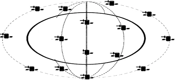
By connecting satellites together, we can cover the globe to establish communication from any place to another on earth. The information is sent by a ground station to the nearest satellite above and then transmitted between the satellites until it reaches the satellite above the destination which then transmits the information down to the destination ground station (see Fig. 1).
[image:2.612.161.462.416.553.2]That information which is propagated between the satellites falls into several data types or traffic such as Navigation data, Payload data or Spacecraft health &status while each of these types of data has different levels of data rates and bandwidth requirements. ISLs that represent the network links of this satellite networks which can be either optical or radio frequency.
Fig. 1 Satellite communication network
mitigation, integration and fabrication.
Table 1. Frequency bands for inter-satellite links
Inter-satellite service Frequency Bands
Radio Frequency
22.55-23.55 GHz 24.45-24.75 GHz
32-33 GHz 54.25-58.2 GHz
Optical
0.8-0.9 µm (AIGaAs laser diode) 1.06 µm (Nd:YAG laser) 0.532 µm (Nd:YAG laser)
10.6 µm (CO2 laser)
II. OPTICAL ISL SYSTEM
[image:3.612.87.519.354.430.2]As space optical inter-satellite link becomes a reality, the structure and design of Optical Satellite Communication network are now feasible. This optical wireless communication (OWC) is considered as next generation technology of FSO satellite networks due to the ability to connect with data rates up to numerous Gbps. Fig. 2 shows the localization of the optical inter-satellite links which were between FIRE and TerraSAR-X. This links were in February 2008 and considered as the first two optical inter-satellite links between two satellites. The first link was put above Central America and the Pacific Ocean with link distance between 3,700 - and 4,700 km. The second optical link was near to the South Pole with The link distance between 3,700 km and 4,875 km.
Fig. 2. Localization of the first two optical inter-satellite links.
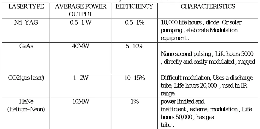
The basic structure of the satellite optical communication system: transmitter, receiver, and PAT system. At first, the transmitter converts electrical signals to optical signals using the laser sources (see table 2).
Table 2. Laser commonly used in satellite communication LASER TYPE AVERAGE POWER
OUTPUT
EEFFICIENCY CHARACTERISTICS
Nd‐ YAG 0.5‐ 1 W 0.5‐ 1% 10,000 life hours , diode Or solar pumping , elaborate Modulation equipment .
GaAs 40MW 5‐ 10%
Nano second pulsing , Life hours 5000 , directly and easily modulated , rugged
CO2(gas laser) 1‐ 2W 10‐ 15% Difficult modulation, Uses a discharge tube, Life hours 20,000 , used in IR range.
HeNe (Helium–Neon)
10MW 1% power limited and
[image:3.612.87.525.500.718.2]The transmitter telescope collimates the laser radiation in the receiver satellite direction after that the optics of two satellites must be aligned with the line of sight during the entire time of communication to establish optical communication successfully. To meet this requirement, the satellites should implement a pointing, acquisition, and tracking (PAT) subsystem, this subsystem has three phases: - Pointing: laser source in the transmitter points its beams towards the direction of the receiver according to the orbit equation using Ephemerides data.
- Acquisition: receiver scans the region of space where it can receive the signal if detects the transmitted beam enters the tracking phase. The duration of this phase is typically 10 seconds. The transmitted beam should be wide to reduce this duration.
- Tracking: in this phase, the transmission between the two satellites becomes continuous by using beacon signal on one satellite and a quadrant detector and tracking system on the other (see figure 3).
[image:4.612.156.452.240.372.2]Finally, the receiver telescope focuses the received beam onto the optical filter which prevents the background radiation from entering the next stages of a subsystem. After that the optical filter pass the received beam to the optical amplifier, the output beam or radiation of amplifier signal convert into an electrical signal by using photodiode.
Fig. 3 Tracking System Scheme
III. COMPARISON BETWEEN OPTICAL AND MICROWAVE ISL SYSTEMS
In the recent years, Optical Wireless Communication (OWC) has been the attractive satellite to satellite cross-links instead of the conventional radio-frequency (RF) system which is visible from a summary of the comparison between RF and optical inter-satellite networks. Table.3 explains the most important terms which are used usually as comparable terms between FSO and RF wireless ISLs.
Table 3. Comparison between FSO and RF wireless ISLs
Terms Microwave link Optical link
Frequencies
22.55 – 23.55 GHZ 24.45 – 24.75 GHZ
32-33 GHZ 54.25-58.2 GHZ
0.8-0.9 μm ( AIGAas laser diode ) 1.06 μm( Nd:YAG laser ) 0.532 μm( Nd:YAG laser )
10.6 μm (CO2 laser )
Data rate Peak data rates of 600 Mbps if the
system using FDM approach . Provide up to 10 Gbps
Transmit power
23 GHz : 117 to 1476 W
33 to 416 W 13 to 168 W 32 GHz : 61 to 763 W 17 to 215 W 7 to 87 W
60 GHz : 17 to 217 W
5 to 61 W 2 to 25 W
Laser (FD Nd:YAG) : 4 to 55 mW 0. 3 to 3. 5 mW
[image:4.612.47.567.466.727.2]Antenna / optics size ( diameter ) 3 ft 4 ft 5 ft 6 inch 12 inch 24 inch
Weight or mass (Kg)
23 GHz 76 to 660 35 to 220 28 to 100 32 GHz 48 to 350 27 to 120 24 to 55 60 GHz 25 to 120
20 to 50 22 to 35
Laser (FD Nd:YAG) :
47 to 50 68 180
Laser (GaAs) : 47 to 50
68 180
Modulation and multiplexing
QPSK , QAM FDM
Continuous optical carrier intensity modulation, direct detection,
WDM – DWDM
Antenna gain 20dB ( Tx Antenna Gain) 20dB( Rx Antenna Gain )
78dB ( Tx Antenna Gain) 112dB( Rx Antenna Gain )
Complexity Low complexity More complexity and sensitivity of all optics
Cost High cost with comparable data rate. Much lower cost with comparable data rate.
Regulations restrictions
RF spectrum which is regulated by national and international agencies up
to 300 GHz
The optical spectrum in space is virgin territory and is currently unregulated.
Beam width
Wider beam width
(e.g., At 10 GHz ,λ= 3 cm with
, D = 1.0m yields 67.2 mrads)
Narrower beam width
(e.g., λ = 1.0 micron with D =
10 cm yields 22.4 µrad)
Noise Noise is mostly thermal and excess noise in the amplifiers
Noise is related to fluctuations of the photon flux being detected that contribute to noise in the
detection system.
Interference
Inter-channel and intra-channel interference Due to close proximity of
RF carriers in RF spectrum.
Optical frequencies are out of these problems.
IV. DISCUSSION AND CONCLUSION
optical ISLs which derives from the necessity of pointing process from one satellite to another over long distances (tens of thousands of kilometers) with small beam divergence angle (micro radians) while the satellites move and vibrate.
REFERENCES
[1] AsmaaZaki M.1, Heba A. Fayed2 , Ahmed Abd El Aziz3, Moustafa H. Aly4 , “ The Influence of Varying the Optical Wavelength on ISL Performance Recognizing High Bit Rates", (IOSR-JECE) , Ver. II (Jan. 2014).
[2] M. Ruggieri (Ed.) , “ Mobile and Personal Satellite Communications 3 “ Proceedings of the Third European Workshop on Mobile/Personal Satcoms (EMPS 98) [3] MorioToyoshima , “ Trends in satellite communications and the role of optical free-space communications “
[4] SHLOMI ARNON AND N. S. KOPEIKA, SENIOR MEMBER, IEEE , “ Laser Satellite Communication Network— Vibration Effect and Possible Solutions “ [5] R. Sun (1), D. Maessen (1), J. Guo(1), E. Gill (1) , “ ENABLING INTER-SATELLITE COMMUNICATION
[6] Prof. Dr. HossamShalaby , Eng. Islam Mohamed Salah Kotb , “ Optical Satellite Communications " Course: Laser and Electro-Optics ( EE-106381). [7] V.W.S. Chan, “ Intersatellite Optical Heterodyne Communication Systems
[8] Committee on Optical Science and Engineering, National Research Council , “ Harnessing Light: Optical Science and Engineering for the 21st Century “ ISBN: 0-309-53884-X, (1998).
[9] Vincent W. S. Chan, Fellow, IEEE, Fellow, OSA , “ Optical Satellite Networks “ JOURNAL OF LIGHTWAVE TECHNOLOGY, VOL. 21, NO. 11, NOVEMBER 2003 .
[10] Berry Smutnya, HartmutKaempfnera, Gerd Muehlnikela, Uwe Sterra, Bernhard Wandernotha, Frank Heinea, Ulrich Hildebranda, Daniel Dallmanna, Martin Reinhardta, Axel Freiera, Robert Langea, Knut Boehmera, Thomas Feldhausa, JuergenMuellera, Andreas Weicherta, Peter Greulicha, Stefan Seela, Rolf Meyerb, Reinhard Czichyc, “ 5.6 Gbps optical intersatellite communication link
[11] DebabrataGoswami , Department of Chemistry, Indian Institute of Technology Kanpur , “ Advanced Optical Developments for inter-Satellite Communication “
[12] GATENBY, P and GRANT.M “ Optical inter-satellite links for space interconnectivity” .
[13] Allen Panahi1, Alex A. Kazemi2 , “ Optical Laser Cross-Link in Space-Based Systems used for Satellite Communications “ .Accro USA LLC, Pasadena, CA91117, 2ARK International, Pasadena, CA 91001.
[14] ]M. WIlTIG AND G. OPPENHAUSER , “ PERFORMANCE OF OPTICAL INTERSATELLITE LINKS “ INTERNATIONAL JOURNAL OF SATELLITE
COMMUNICATIONS, VOL. 6, 153-162 (1988)
[15] Denise S. Ponchak and Rodney L. Spence , , “ Application of Intersatellite Links to Domestic Satellite Systems " , NASA Technical Memorandum 87215. [16] Fadi Jawdat Ghosna ," Pulse Position Modulation Coding Schemes for Optical Inter-satellite Links in Free Space "
[17] Geoffrey Hyde & Burton I. Edelson , “Laser satellite communications : current status and directions “
[17] MorioToyoshima , Walter R. Leeb , HirooKunimori , Tadashi Takano , “ Comparison of microwave and light wave communication systems in space applications “
[18] B. CHIDHAMBARARAJAN*, V. JAWAHAR SENTHILKUMAR1, S. KARTHIK1, AND DR.S. K. SRIVATSA2 , “ Satellite laser communication networks