© 2018, IRJET | Impact Factor value: 6.171 | ISO 9001:2008 Certified Journal | Page 3717
CONTROLLER BASED MODEL FOR ACTIVE AND REACTIVE POWER IN PV
SYSTEMS DURING UNBALANCED GRID VOLTAGE
Sneha Kumari
1, Dr. Samina Elyas Mubeen
21
M.Tech scholar, EEE Department, Radharamam Engineering College, Bhopal
2
H.O.D, EEE Department, Radharamam Engineering College, Bhopal.
---***---Abstract -
Now a day the population is increasing day by day, at the same way the industries are also increasing. So thedemand for power is also increasing. As the conventional
sources of energy are depleting and the cost of energy is rising day by day. In order to minimize the cost and to generate the power the alternative sources of energy are non conventional energy sources. The generated maximum power is delivered to the grid through an inverter. The output power of PV units is not constant during a day; it varies with changes in atmospheric conditions so robustness is essential.
In this paper a robust partial feedback Linearizing controller and LCL filter is proposed to analyze the grid connected PV system. The inclusion of LCL filter dynamics affects the stability of the system for which a peak amplitude response at the resonance frequency of the LCL filter exists, and the parameters of LCL filter are chosen correctly, otherwise the dynamic stability of the system will be reduced. In performing the simulation, the values of inductor and capacitor of the LCL
filter are selected depending on the filter design. The
effectiveness of the proposed controller is tested for different system conditions as well as changes in atmospheric conditions, such as decrease in solar irradiation, single-line-to-ground fault and three-phase short-circuit faults and the results are compared with that of a partial feedback linearizing controller. The simulations were performed using MATLAB/SIMULINK.
Key Words: Voltage source inverter, Photovoltaic systems,
Linearizing controller. Dc-dc converter,MPPT
1. INTRODUCTION
Among the various sources of non conventional energy sources [1], PV is a promising source. Since the power from sun mainly depends on the irradiation and weather conditions. So MPPT [12] plays an important role in the PV
system systems. In a grid connected PV System [2] the
control objectives are met by using PWM technique. It consists of two cascaded control loops .The inner current control loop is used to maintain the power quality, to control the duty ratio for the generation of sinusoidal output current and the outer control loop is voltage control loop which is used to track the MPP. Normally current controllers are used in tracking method. Normally to operate the PV systems at MPP nonlinear controllers are used; but they do not account for the uncertainties in the PV system. But there is more development in the field of control theory and robust linear controllers for linear systems in the presence of
uncertainties through the control scheme which is often obtained from linear matrix in equality (LMI) methods, from the last few years. A feed forward approach is proposed to control the dc-link voltage and current, and the robustness is achieved by modal analysis. The controller design methods as presented in and are based on linearized models of nonlinear PV systems. Normally, PV systems are time varying in nature.
[image:1.595.321.549.449.662.2]A nonlinear proportional-integral-derivative (PID) controller is presented to overcome the drawbacks of linear controllers, where improved performance is reported. A Lyapunov-based control scheme for a grid connected PV inverter is presented where an adaption law is included to improve the robustness. However, it is well known that the adaption technique is useful for systems with slow parameter variations which are not the case for PV systems as the changes occur rapidly. A sliding mode controller for a nonlinear grid-connected PV system is proposed along with a new MPPT technique [3] for
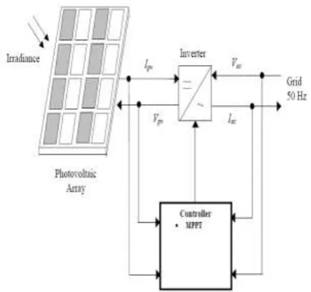
Fig- 1: Basic Configuration of Grid Connected PV Generation
© 2018, IRJET | Impact Factor value: 6.171 | ISO 9001:2008 Certified Journal | Page 3718 A grid connected PV system [4] converts sunlight directly
into ac electricity. The main purpose of the system is to reduce the electrical energy imported from the electric utility .Fig.1 shows a functional diagram of the basic configuration of a grid-connected PV system. By using a inverter [8] the dc output of the PV is converted in to ac output. The controller of this inverter implements the entire main control: Maximum Power Point Tracking (MPPT).
2. SOLAR IRRADIANCE
Solar irradiance is the radiant power incident per unit area
upon a surface. It is usually expressed in w/m2. Radiant
power is the rate of flow of electromagnetic energy. Sunlight consists of electromagnetic waves composed of photons at different energies, which travel at constant speed. Solar radiation has a wave like characteristic with the Wavelength (λ) inversely proportional to the photon energy (E).
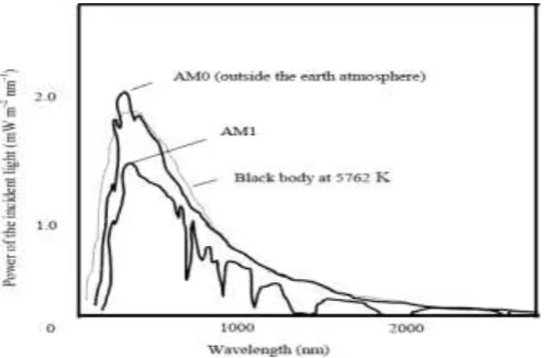
The spectrum of the sunlight is shown in Fig.2.1. The light from the sun has a spectrum close to the light from a black body at a temperature of 5762K. The dotted line shows black body radiation at this temperature. This is in good agreement
with the AM0curve which shows the spectrum outside the
earth’s atmosphere on a plane perpendicular to the sun at the mean earth-sun distance. The power density outside the earth's atmosphere is 1367 W/m2 and this is known as the solar constant. Air mass refers to the relative path length of the direct solar beam through the atmosphere. The path of the light through the atmosphere is shortest when the sun is at its zenith (perpendicular to the earth's surface), the path length is 1.0 (AM 1.0) and this gives rise to the AM1spectrum. Obviously, the sun is not always at the zenith. When the angle of the sun from zenith increases, the air mass increases so that at an angle of 48.2° the air mass is 1.5and at an angle of 60° the air mass is 2.0 shown in Fig.2.2. AM 1.5 has been adopted as the standard sunlight spectrum for terrestrial arrays.
Fig - 2.1 The Spectrum of Sunlight
Usually, the peak power output of a PV inverter is measured under AM1.5 (1kW/m2) sunlight with a junction temperature of 25°C. This is the so-called standard test condition (STC).
Fluctuation of the solar irradiance due to passage of clouds over a PV array is the main reason behind the fluctuation of the output power of PV systems. There are 10 reported cloud patterns, with cumulus clouds (puffy clouds looking like large cotton balls) and squall lines (a solid line of black clouds) causing the largest variations in the output power of PV systems. Squall lines can cause the output power of a PV system to fall to zero, and thus, they lead to the worst-case scenario for the operation of the system. However, squall lines are predictable, and thus, the periods of time during which the PV system will be out of service can be predicted. On the other hand, cumulus clouds result in lower loss of the PV power, but they cause the output of the PV system to fluctuate more frequently as the irradiance fluctuates due to the passage of such clouds. The time period of fluctuations can range from few minutes to hours depending on the wind speed, the type and size of passing clouds, and the area covered by and topology of the PV system.
[image:2.595.38.286.536.699.2]The most severe fluctuations in the output power of PV systems usually occur at maximum irradiance level around noon. This period usually coincides with the off-peak loading period of the electric network, and thus, the operating penetration level of the PV system is greatest. The severity of PV power fluctuations on the electric network is governed by several factors, such as: Type of clouds, Penetration level, and size of PV system, Location of the PV system, Topology of the PV system, and Topology of the electric network.
Fig-2.2 Air mass concept
3. PV CELL CHARACTERISTIC
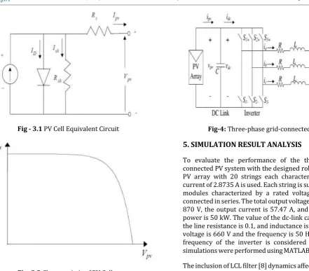
The equivalent circuit [6] is shown in Fig .3 and described by Equation (3.1) represents a PV cell.
(3.1)
© 2018, IRJET | Impact Factor value: 6.171 | ISO 9001:2008 Certified Journal | Page 3719
[image:3.595.37.273.83.464.2]Fig - 3.1 PV Cell Equivalent Circuit
Fig -3.2 Characteristic of PV Cell
4
.
PHOTOVOLTAIC SYSTEM MODEL
PV inverter system which comprises of a PV panel, associated with a dc-dc converter and a widely used dc-ac pulse width modulation (PWM) inverter connected to the utility grid. A single phase PV power conditioning system is often selected for low power applications (< 3 kW) i.e., residential applications. For higher power applications i.e., commercial or industrial applications, a three-phase PV power conditioning system is preferable.
Schematic diagram of a three-phase [5] grid-connected solar system which is the main focus of this paper is shown in Fig.4 .The considered PV system consists of a PV array, a dc-link
capacitor C, a three-phase inverter [7] , and a filter inductor L
and is connected to the grid with voltage ea, eb, and ec. PV cell
is a simple p-n junction diode which converts solar irradiation into electricity. Since the output voltage of PV cell is very low, a number of PV cells are connected together in series in order to obtain higher voltages. A number of PV cells are put together and encapsulated with glass, plastic, and other transparent materials to protect from harsh environment, to form a PV module [13]. To obtain the required voltage and power, a number of modules are connected in parallel to form a PV array.
Fig-4: Three-phase grid-connected PV system
5. SIMULATION RESULT ANALYSIS
To evaluate the performance of the three-phase grid-connected PV system with the designed robust controller, a PV array with 20 strings each characterized by a rated current of 2.8735 A is used. Each string is subdivided into 20 modules characterized by a rated voltage of 43.5A and connected in series. The total output voltage of the PV array is 870 V, the output current is 57.47 A, and the total output power is 50 kW. The value of the dc-link capacitor is 400 F, the line resistance is 0.1, and inductance is 10 mH. The grid voltage is 660 V and the frequency is 50 Hz. The switching frequency of the inverter is considered as 10 kHz. The simulations were performed using MATLAB/SIMULINK [14].
The inclusion of LCL filter [8] dynamics affects the stability of the system for which a peak amplitude response at the resonance frequency of the LCL filter exists, and if the parameters of LCL filter [9] are not chosen appropriately, the dynamic stability of the system will be degraded. To perform the simulation, the inductor and capacitor values of the LCL filter are selected based on the filter design processes as presented in which are 10mH and 3.1 F.
Since partial feedback linearizing controllers are sensitive to system parameters, it is essential to have an exact system model in order to achieve good performance. But for real life grid connected PV systems, there often exist inevitable uncertainties in constructed models. In addition, uncertain parameters exist that are not exactly known or difficult to estimate. Therefore, to evaluate the performance of the designed robust control scheme, it is essential to consider these uncertainties.
© 2018, IRJET | Impact Factor value: 6.171 | ISO 9001:2008 Certified Journal | Page 3720
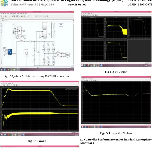
[image:4.595.32.292.81.296.2]Fig - 5 System Architecture using MATLAB simulation.
[image:4.595.34.563.259.731.2]Fig-5.1 Power
Fig-5.2 Vg and Ig
Fig-5.3 PV Output
Fig - 5.4 Capacitor Voltage
6.1 Controller Performance under Standard Atmospheric Conditions
In this case study, the standard values of the solar irradiation
(1 kW-2) and environmental temperature (298 K) are
[image:4.595.34.319.327.720.2]© 2018, IRJET | Impact Factor value: 6.171 | ISO 9001:2008 Certified Journal | Page 3721
1 1.01 1.02 1.03 1.04 1.05 1.06 1.07 1.08 1.09 1.1
[image:5.595.41.282.79.264.2]-100 -80 -60 -40 -20 0 20 40 60 80 Time(sec) V o lt a g e ( * 1 0 V ) a n d C u rr e n t (A ) PFBLC Grid Voltage RPFBLC
Fig - 6.1 Controller performance at standard atmospheric conditions
6.2 Controller Performance under Changing Atmospheric Conditions
At this stage, it is considered that the PV unit operates under standard atmospheric conditions until 1 sec. At t = 1 sec, the atmospheric condition changes in such a way that the solar irradiation f the PV unit reduces to 70% from the standard value. Under this situation though, the partial feedback linearizing controller (PFBLC) is able to maintain the stability of the system but still there are some phase differences between the grid current and voltage [11] but with the robust partial feedback linearizing controller (RPFBLC), there are no phase differences. Thus, the designed controller performs well an in changing condition which is shown in Fig.6.2, from which it can be seen that the PV unit operates under the standard atmospheric condition up to 1.1 s and changing atmospheric conditions up to 1.2 s. After that, it operates under standard conditions and the designed controller maintains the operation of the system at unity power factor.
1 1.05 1.1 1.15 1.2 1.25 1.3
-100 -80 -60 -40 -20 0 20 40 60 80 100 Time(sec) V ol ta ge ( *10V) a nd C ur re nt ( A ) Grid Voltage PFBLC RPFBLC
Fig.6.2 Controller performance at changing atmospheric conditions.
6.3 Controller Performance During Short-Circuit Faults in the System
In this subsection, the robust performance of the controller is evaluated by applying a three-phase short circuit and single-line-to-ground fault at the output of the inverter. For both cases, the following fault sequence is considered:
Fault occurs at 1.5 s;
Fault is cleared at 1.6 s
Where the pre fault and post fault operations of the PV system are considered at standard atmospheric conditions. With this fault sequence, the following two cases are considered to evaluate the performance of the designed controller.
Case 1: Controller performance during three-phase short circuit fault:
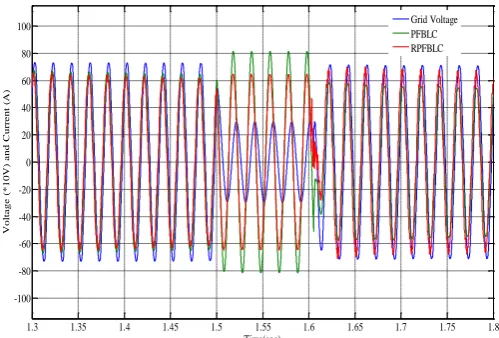
In this case study, a three-phase short-circuit fault is applied at the output terminal of the inverter with the aforementioned fault sequence. The grid-connected PV system is unable to generate active power due to three-phase voltage collapse. During the faulted condition, the voltage of each phase will be reduced, and the current of each phase will be increased. But the controller reacts quickly, after clearance of the fault. With the designed robust controller, the post fault voltage and current are in phase as shown in Fig.5.3. Still there exists a phase difference between voltage ¤t shown in Fig.6.3, when the uncertainties are not considered in the controller design.
1.3 1.35 1.4 1.45 1.5 1.55 1.6 1.65 1.7 1.75 1.8
[image:5.595.310.560.470.639.2]-100 -80 -60 -40 -20 0 20 40 60 80 100 Time(sec) V ol ta ge ( *10V) a nd C ur re nt ( A ) Grid Voltage PFBLC RPFBLC
Fig-6.3 Controller performance during the three-phase short-circuit fault
Case 2: Controller performance with a single line-to-ground fault
[image:5.595.41.284.541.722.2]© 2018, IRJET | Impact Factor value: 6.171 | ISO 9001:2008 Certified Journal | Page 3722 stiffness of the grid. At this time, according to the principle of
negative-sequence current injection the proposed controller will inject negative-sequence current. When a single line to ground fault occur at the inverter, then there is a voltage imbalance due to the negative sequence voltage component. Since the grid voltage is stiff, this imbalance may also occur at grid supply point. Consider that there is a single line to ground fault occurred at phase ’B’ to the ground. The voltage of phase ‘B’ only reduced to zero as shown in Fig.6.4. As shown in fig.6.4 the voltage (Blue line) and current (red line) are in phase with each other, so the controller offers unity power factor. By comparing fig. 6.3 & fig 6.4, there is a small phase difference between voltage and current in fig 6.3 as that of fig 6.4 because the severity of single line to ground fault is less compare to three phase faults.
1.3 1.35 1.4 1.45 1.5 1.55 1.6 1.65 1.7
[image:6.595.313.554.81.267.2]-150 -100 -50 0 50 100 150 Time(sec) V ol ta ge ( *10V) a nd C ur re nt ( A ) PFBLC Grid Voltage RPFBLC
Fig.6.4 Controller performance during the single-line-to-ground fault
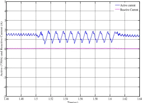
The positive sequence currents and negative sequence powers of single line to ground fault are also shown in figures 6.5 and 6.6 respectively.
1.46 1.48 1.5 1.52 1.54 1.56 1.58 1.6 1.62 1.64
-5 -4 -3 -2 -1 0 1 2 3 4 5 Time(sec) A c ti ve ( *50A) a nd R e a c ti ve C ur re nt ( A ) Active current Reactive Current
Fig.6.5 Positive-sequence active (Iq) and reactive (Id)
current during the single-line-to-ground fault
1.48 1.5 1.52 1.54 1.56 1.58 1.6 1.62
[image:6.595.42.283.272.433.2]-10 -8 -6 -4 -2 0 2 4 6 8 10 Time(sec) A c ti ve ( *10kW ) a nd R e a c ti ve ( *30VA R ) Active Power Reactive Power
Fig-6.6 Negative-sequence active (P) and reactive (Q) power during the single-line-to-ground fault
7. CONCLUSION
In this paper the concept of inverter control types, Synchronization and control of 3-ø grid connected inverter, Symmetrical components, Voltage source inverter, Control of dc link voltage, Energy storage in PV systems, Energy storage technologies and Battery parameters is introduced and discussed. A robust partial feedback Linearizing controller is the good controller for the grid connected PV system to maintain the grid voltage and currents in phase with each other and also maintain the power factor at unity. Instead of considering network parameters only PV system parameters and states need to be known. The proposed controller also improves the overall stability of the system under structured uncertainties..Thus by providing strong robustness against the changes in parameters and variations in atmospheric conditions irrespective of the network parameters and configuration this controller gives effective performance.
A three phase grid connected inverter is analyzed to illustrate the effectiveness of the proposed robust non linear control scheme. In order to validate the proposed topology, simulation is carried out using the Matlab/Simulink.
8. REFERENCES
[1] D. M.; Fuller Chapin, C. S.; Pearson, G. L. Affiliation. Applied. Phys, vol. 25, pp. 676.
[2] European Photovoltaic Industry Association.(2014). “Global market outlook for photovoltaic 2014-2018. Availablehttp://www.epia.org/fileadmin/
userupload/Publications/44_epia_gmo_report_ver_17_mr.pf.
[image:6.595.42.282.533.707.2]© 2018, IRJET | Impact Factor value: 6.171 | ISO 9001:2008 Certified Journal | Page 3723 [4] S. Jain and V. Agarwal, “A Single-Stage Grid Connected
Inverter Topology for Solar PV Systems With Maximum Power Point Tracking,” IEEE Trans. Power Electron., vol. 22, no. 5, pp. 1928–1940, Sept. 2007.
[5] F. Gonzalez-Espin, G. Garcera, I. Patrao, and E. Figueres, “An Adaptive Control System for Three-Phase Photovoltaic Inverters Working in a Polluted and Variable Frequency Electric Grid,” IEEE Trans. Power Electron., vol. 27, no. 10, pp. 4248–4261, Oct. 2012.
[6] W. J. Smolinski,“Equivalent circuit analysis of power system reactive power and voltage control problems,” IEEE Trans. Power Apparatus and Systems, no. 2, pp. 837–842, Feb. 1981.
[7] M. Liserre, F. Blaabjerg, S. Hansen, "Design and control of an LCL-filter based active rectifier", IEEE Trans. Ind. Appl., vol. 41, no. 5, pp. 1281-1291, Sep./Oct. 2005.
[8] Y. Tang, P.C. Loh, P. Wang, F.H. Choo, F. Gao, "Exploring inherent damping characteristics of LCL-filters for three phase grid-connected voltage source inverters", IEEE Trans. Power Electron., vol. 27, no. 3, pp. 1433-1443, Mar. 2012
[9] J. Dannehl, M. Liserre, F.W. Fuchs, "Filter-based active damping of voltage source converters with LCL filter", IEEE Trans. Ind. Electron., vol. 58, no. 8, pp. 3623-3633, Aug. 2011.
[10] H. Muaelou, Khaled M. Abo-Al-Ez, and Ebrahim A. Badran, "Control Design of Grid-Connected PV Systems for Power Factor Correction in Distribution Power Systems Using PSCAD" International Journal of Renewable Energy Research (IJRER), Vol. 6, No. 8, 2015, p. 1092-1099.
[11] A. Omole, "Voltage Stability Impact of Grid-Tied Photovoltaic Systems Utilizing Dynamic Reactive Power Control", South Florida. Ph.D. Thesis, 2010.
[12] S. Malki, "Maximum power point tracking (MPPT) for photovoltaic system." University M’hamed Bougara Bomerdes, M.Sc. Thesis 2011.
[13] M. Calais, V. G. Agelidis, "Multilevel converters for single-phase grid connected photovoltaic systems—An overview", Proc. IEEE Int. Symp. Ind. Electron., pp. 224-229, 1998
[14] Abu Tariq, M. Asim, and M. Tariq. “Simulink based modeling, simulation and Performance Evaluation of an MPPT for maximum power generation on resistive load." 2nd International Conference on Environmental Science and Technology, Vol. 6, 2011, p. 397-401.
[15] R. Stala, S. Pirog, M. Baszynski, A. Mondzik, A. Penczek, J. Czekonski, S. Gasiorek, "Results of investigation of multicell converters with balancing circuit—Part I", IEEE Trans. Ind. Electron., vol. 56, no. 7, pp. 2610-2619, Jul. 2009.