© 2018, IRJET | Impact Factor value: 6.171 | ISO 9001:2008 Certified Journal | Page 3410
A Solar PV based Cascaded DC-DC Converter for Speed Control of DC
motor with PWM+PFM Control
Amal Sukumaran
1, DR. Sreekala K
2MTech student , Power Electronics Batch, Electrical and Electronics Engineering Department at Sreenarayana
Gurukulam College of Engineering, Kadayiruppu,Kerala
Professor, Electrical and Electronics Engineering, Sreenarayana Gurukulam College Of Engineering, Kadayiruppu,
Kerala
---***---
Abstract
- A DC motor fed from a solar PV panel and cascaded DC – DC converter with PWM+PFM control is proposed in this paper. The cascaded DC –DC converter is provided at the output of solar voltage source is used to eliminate the instability of the supply voltage and to provide ripple free and reliable DC voltage across the load. Here the load used is a DC motor, in which the speed control is carried out. The proposed converter ensures that the speed can be controlled over a broader range and the power loss in the circuit is minimized. The proposed method of speed control is compact and less costlier than other methods of speed control like armature control and field control.Key words
: Single switch, cascaded converters, PWM control , PFM control1 INTRODUCTION
The renewable energy systems has been getting a great importance now a days in the modern power system. Commonly used renewable sources now a days are solar, geothermal, wind , and ocean energy sources. Potential emission of greenhouse gases , probable instability of the
Power plant located area, non-availability of geothermal sources , higher cost of generated electricity , higher cost of pumping and distribution makes the geothermal energy lee reliable compared to other sources. The main disadvantage of wind energy is that it is location specific. Also erection of wind power plant is costlier. All these factors necessitate the usage of solar energy as potential power source in the non-conventional power system. A typical solar system employs PV panels , each comprising a number of solar cells , which generate electrical power. PV installations can be either ground-mounted, mounted on the roof top or wall mounted. The mount may be fixed, or use a MPPT ( maximum power point tracker ) to follow the sun across the sky.
Solar PV system has many advantages as an energy source compared with other renewable energy sources. Its operation generates no pollution and no greenhouse gas emissions, has large availability .PV systems have the major disadvantage that the power output is dependent on direct sunlight, so about 10-25% is lost if a tracking system is not used .Dust, clouds, and other things in the atmosphere also leads to lesser power output. Another
main issue is the concentration of the production in the hours corresponding to main insolation, which don't usually match the peaks in demand in human activity cycles. Hence the power output from the solar PV panel will be a fluctuating DC source due to the instability factors from the environment.
The power obtained from the solar panels is DC which requires a DC-DC conversion before it can be applied to the grid. When the load side requirement is lesser than the power supplied by the solar panel, the excess power is saved in a battery. In standalone and other small scale applications, DC –DC converters are used as an intermediate between the solar panel and the battery. Normally the conventional converters use at least one switch in each converter. The two converters which is either connected in series or in parallel are controlled independently for circuit simplicity. The existing system consists of two cascaded converters which share a single switch. As a result the the existing system has lesser number of switches and components. The switch shared by the cascaded converters are controlled using a combination of PWM and PFM technique.
Now a days in the modern world , where the mechanical human labor has been taken over by machines, their driving part was replaced by the motors. Different types of motors are used for different purposes. For low and medium load applications, DC motors are widely used. They are being extensively used in lathes, conveyors, automobiles and in domestic applications. For the ease of use and for more power saving capability there is an increasing need for the speed control of DC motors.
2. DC MOTOR FED FROM A CASCADED CONVERTER
AND H BRIDGE
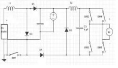
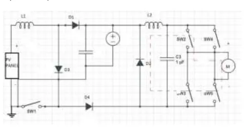
The circuit of the proposed system consist of a cascade converter fed from a solar panel and an H bridge converter. The DC motor is driven by H Bridge circuit. H Bridge circuit is used for the forward and reverse motoring of the DC motor. Like the conventional cascaded converter, the input side converter has energy storage components L1
and L2 as well as capacitors C1 and C2. The converters charge
the inductors L1 ,L2 and capacitors C1 and C2 as normal. The
© 2018, IRJET | Impact Factor value: 6.171 | ISO 9001:2008 Certified Journal | Page 3411 controlling of the sharing switch both the converters can
[image:2.595.312.557.69.198.2]work independently.
Fig 1 Circuit Diagram
Followed by the cascaded converter there is an H bridge converter. The H Bridge converter consists of 4 transistors which are connected in the form of an H Bridge as shown below. The current flow through the H Bridge converter determines the direction of rotation of the motor. When the flow of load current through the H bridge converter is in the forward direction then the motor will rotate in the clockwise direction and also if the load current direction through the H Bridge is reversed, then the motor will be rotating in the anticlockwise direction. A toggle switch in the H bridge converter is used to control the direction of rotation.
. An H bridge is built with four switches (solid-state or mechanical). When the switches S1 and S4 (according to the first figure) are closed (and S2 and S3 are open) a positive voltage will be applied across the motor. By opening S1 and S4 switches and closing S2 and S3 switches, this voltage is reversed, allowing reverse operation of the motor.
S1 S2 S3 S4 MOTOR MOVEMENT 1 0 0 1 MOTORMOVESRIGHT 0 1 1 0 MOTORMOVESRIGHT 0 0 0 0 MOTOR COASTS 0 1 0 1 MOTOR BREAKS
TABLE1-H bridge converter switching
3. MODES OF OPERATION
Based on the assumptions made , there exists three different modes for the converter. The operation of the second stage in discontinuous conduction mode is responsible for these modes from the general topology.
3.1 Mode 1 Operation
During this mode the sharing switch S1 is turned ON. And the current sharing path is formed as shown in the figure. The current flow path in this mode consists of inductor L1, diode D1 and D3 in the first stage of the
[image:2.595.87.275.114.222.2]converter.
FIG 2 Mode 1 Operation
During this mode the inductor L1 charges in linear direction.
Therefore the slop of inductor L1 is obtained as
dL1/dT = Vin/L1
Where IL1 is the inductor current of L1
At the same time , the converter in the stage 2 transfers energy to the load via the current path mentioned in the circuit diagram. In this process the inductor L2 charges
linearly with a slop given by,
diL2/dt = Vb-Vo/L2
Vo output voltage / voltage of the load
Vb = Voltage of the storage / battery
iL2 = current through the inductor L2
3.2 Mode 2 Operation
At the end of mode 1 the switch S1 is de energized. The first stage , that is the PFM controlled converter charges
the battery . The inductor L1 retains the current L1 . the
inductor will be charging with a slop given by,
[image:2.595.312.556.533.683.2]diL2/dt = -V0/L2
FIG 3 Mode 2 Operation
© 2018, IRJET | Impact Factor value: 6.171 | ISO 9001:2008 Certified Journal | Page 3412 in mode 1 the storage is isolated from the supply. The design
of inductor L2 is such that, it delivers current to the load until the switch is turned on during next cycle. Also it may be note that the current delivered by the inductor L2 and that delivered by the batter during the previous mode will be almost equal. During the same time the charge in the inductor L1 starts discharging. This mode ends when the inductor current Il2 approaches zero.
2.3 Mode 3 operation
When the current Il1 across the inductor L1 decreases to zero, the circuit enters the working mode 3. The state of the switch is still OFF , that means there is no current path through the switch S1. Current in the inductor L1 is zero during this mode . The inductor L2 continues to discharge , following the slop defined by,
[image:3.595.42.281.298.424.2]diL2/dt = -V0/L2
FIG 4 Mode 3 operation
The load current freewheels through R2,D2 and the load. The inductor is so designed, taking the duty ratio of the switch in to consideration, so that, as soon as the inductor L2 is discharged fully, the mode 3 must end and switch S1 must be turned on with zero delay. Any delay incurred, causes the load current to be discontinuous which is undesirable.
4. THE CIRCUIT DESIGN PROCESS
Accurate design of the components of the circuit plays an important role in obtaining good conversion efficiency in the cascaded converters. The equations for the design of various components has been derived considering the operating modes of the converter. In the present circuit topology we can see that, values of L1,L2,C1,C2 has to be
calculated.
To start with let us analyze both the converters separately. For the sake of simplicity, let us take the case of second stage first. Since the converter 2 operates in continuous conduction mode (CCM), the duty ratio can be calculated from the following formula.
D is the duty cycle
V0 is the output voltage
VB is the voltage of the battery.
From the duty ratio calculated above , value of the equivalent input current Ib0 is obtained from the following relation
Ib0= DI0
Where I0 represents the current across the load or output current.
From the duty ratio so obtained and the frequency f the range of the inductance L2 can be calculated by the following equation
Where RL is the load resistance and f is the frequency.
If the value of L2 is lesser than that prescribed above
, the stage 2 of the circuit may fall into discontinuous conduction mode. Hence it is necessary that the inductor L2
must supply the load until the switch S is turned on in the succeeding mode. The above relation is used to make the converter stay in the boundary of DCM and CCM.
The capacitor C2 or the output capacitor is designed so that
output ripples stays in the required levels. Once the value of the inductor L2 is reckoned, the size of the capacitor C2 can
be obtained by,
Having Designed the capacitor and inductor size , mode 1 design has been completed. The first stage design is done based on the design of stage 2. Since the converter operation is assumed ideal, the input current and the equivalent output current is equal. This relation can be expressed as ,
Where Vb is the voltage of the battery
Ibi is the equivalent input current
Ib0 is the equivalent output current
© 2018, IRJET | Impact Factor value: 6.171 | ISO 9001:2008 Certified Journal | Page 3413 We know that the first stage operates in
discontinuous conduction mode. So the value of the inductor L1 , that is the inductor of the converter 1 must lie in the
required range. If the value of inductor L1 exceeds the range
the converter turns to continuous conduction and the operation of the PFM will be harder. Hence the value of L1 is
calculated for CCM-DCM boundary,
Using the relationship given below, the value of inductor L1 can be accurately calculated from the parameters obtained.
Where G1 is the gain of the converter of the first stage .
rearranging the terms the inductor of L1 can be found from
the following expression,
The equation mentioned above may not meet the limit requirements of the inductor L1. So trial and error method can be used to find the accurate value of the parameter. Thus we have found the active and passive components in the existing system such as values of all the inductors and capacitance. But for PWM control, it must have the value of duty cycle D and for PFM control in the first stage , we must know the value of duty ratio D and frequency . However, for the first stage the duty ratio is assumed relatively constant, only the frequency will be variable.
The design of the H bridge circuit is comparatively simpler . the only condition to be satisfied while designing the h bridge circuit is that , the current rating of the switch must be greater than the load current flowing through the bridge. Once duty ratio is known,
DIo=Ibo
Where Io is the load current &
Ibo is the equivalent input current.
Io = Ibo/D
Hence the transistor is selected such that its current rating > Equivalent input current/ Duty cycle.
5. MOTOR SPEED CONTROL USING CASCADED
CONVERTERS WITH PWM AND PFM CONTROL
[image:4.595.318.551.256.371.2]The output of the cascaded converter is fed to an H bridge circuit. The H bridge, driven by high and low output of the microcontroller, is used to control the direction of rotation of the motor. The speed of rotation of the motor is continuously detected by an infrared sensor. In the sensor the infrared rays are continuously emitted to an infrared receiver during that time the output of the IR sensor will be low that is zero. When the blade of the motor come in between the IR sensor and receiver IRS gets blocked by the leaves of the fan find output of the sensor circuit will be 5 volt.
FIG 5 –circuit description
Square pulse will be generated at each time the IRS gets blocked by the fan leaves. This signal is fed to the microcontroller. The microprocessor is program such that, it reads the RPM and stores it in the memory. The Potentiometer in the circuit is used to set the rated or reference speed. The output from the Potentiometer is also fed back to the microprocessor. The Potentiometer is designed such that the voltage in the Potentiometer various between zero to 5 volt. Let us assume that the Potentiometer voltage is set at 3 volt. The 3 volt fed to the microcontroller is converted to corresponding RPM by the program, say 1000 RPM. RPM detected from the motor feedback is the original motor speed and the RPM set by the Potentiometer is the reference speed.
FIG 6 - Potentiometer
[image:4.595.373.505.576.670.2]© 2018, IRJET | Impact Factor value: 6.171 | ISO 9001:2008 Certified Journal | Page 3414 speed set by the Potentiometer the PWM width will be
increased and speed is maintained to the rated value automatically.
6. THE PWM AND PFM CONTROL OF THE SYSTEM
6.1 The PWM control
[image:5.595.82.246.276.320.2]The DC motor fed from an H Bridge converter is controlled by a single switch cascaded converter which is regulated simultaneously by PWM and PFM control. The speed feedback from the motor , that is the original speed, is compared with the reference speed (set by the Potentiometer ) to control PWM to drive the switch. The PWM signal provided by the microprocessor is given to MOSFET via optocoupler.
FIG 7- PWM control
The speed of the motor sensed by the tachometer is fed to the microcontroller to generate corresponding pulses. The PWM signal provided by the microcontroller is fed to the switch in the first converter of the cascaded converter. Output of the PWM will have only a lower amplitude which is insufficient to drive the MOSFET so and optocoupler is provided in order to provide drive signal for the MOSFET turn on. When the speed of the motor is slower than the reference speed set by the user, the width of the PWM signal is increased to speed up the motor to the rated value. Similarly when the speed of the motor is greater than the reference speed the width of the PWM signal is reduced and draws less voltage from the battery , and the speed of the motor is subsequently decreased to attain its rated value. So the proposed system becomes a closed loop circuit, in which the motor output is fedback to control the PWM of the first converter.
6.2 PFM control
The voltage required to generate PFM signal is taken across the capacitor c or across the battery in the proposed circuit . The maximum charge the battery can attain is 14.4 volt. The voltage which is taken across the battery or the capacitor can be greater than or less than 14.4 volt. This voltage cannot be directly fed back to the microprocessor since it cannot with stand higher voltage. Hence the voltage is fed to the microcontroller via a voltage divider( 1 ohm to 10 ohm)
FIG 8- PFM control
is used to buck the voltage For the protection of the microprocessor. Thus a lower voltage which comes around 1.1 volt is fed to the microprocessor. The microprocessor will read the voltage across the capacitor and compare it with the rated value. If the value read by the Microprocessor across the capacitor is less than 14.4 volt let's say 12 volt the frequency is decreased and the converter will draw more voltage from the Solar PV panel to obtain the rated voltage. Here the width of the pulse is never varied, but the frequency of the pulse is varied for maintaining the output voltage of the cascaded converter constant. However when the voltage read by the microprocessor across the capacitor is greater than the rated voltage that is 14.4 volte the frequency of the pulse is increased and the converter will draw a lower voltage from the cascaded converter to bring back the voltage to the rated value. Both PWM and PFM control is applied to a single switch which is shared by the cascaded converters
7. SIMULATION RESULT
The circuit has been modelled on the MATLAB and simulated. From the simulation results it can be seen that, the motor runs almost at constant speed of approximately 60 rad /sec. also the armature current is almost 0.215 A. a constant electrical torque is also obtained of the order of 0.01 nm. By adjusting the width of the PWM signal, the speed of the motor is varied.
FIG 9 – Simulation results
[image:5.595.309.564.425.606.2]© 2018, IRJET | Impact Factor value: 6.171 | ISO 9001:2008 Certified Journal | Page 3415
8. HARDWARE IMPLEMENTATION
[image:6.595.51.274.185.357.2]Hardware of the proposed converter is implemented using designed values and prototype is tested. The experimental setup of the hardware is shown below. The main components of the converter is cascaded DC-DC converter, PIC16F877A microcontroller, an H bridge circuit a tachometer with IR sensor and an LCD display.
FIG-10 Hardware implementation
9. EXPERIMENTAL RESULTS
[image:6.595.317.548.284.388.2]A hardware prototype is designed and tested. It is seen that the speed control by varying the PWM of the switch at converter one is smooth and fluctuation free. Waveforms from the experiment indicates that both the converters works in continuous conduction mode and discontinuous conduction mode simultaneously. This is shown by the fig.
Fig 11- Converter voltages
The battery current ib and the converter voltage Vcon behaves
as follows,
Fig 12- Battery current Ib and Vcon
The motor speed control over a range of 500-1500 rpm can be obtained. Using the toggle switch at the H bridge converter , forward and reverse motoring is obtained. The results are tabulated as below.
SL
No. ARNATURE CURRENT (A) ELECTRIC TORQUE(nm) SPEED (rad/s)
1) 0.2 0.01 62.06
2) 0.25 0.0125 62.3
3) .4 0.045 91
Table 2
10. CONCLUSION AND FUTURE SCOPE
10.1 CONCLUSION
This project has presented the speed control of DC motor fed from a cascaded converter controlled by both PWM and PFM technology which is powered by solar PV panel. The single switch topology which operated with auxiliary diodes , results in reduction of the total switching losses. Also costly control circuitry for driving the additional switch can be avoided by using this switch sharing technology. Since switch sharing is adopted in converter, additional control variable , that is frequency has to be used. The DC motor is driven by the H bride converter. The RPM output of the DC motor is converter to electric pulses with the help of PIC16F877A microcontroller and given as feed back to control the PWM of the first circuit. Hence closed loop circuit is used to control the speed of the DC motor. This results in constant and steady motor output with minimized fluctuations. Drawing of sufficient power from the panel and monitoring charging and discharging of the battery is done via PFM control. Thus with the help of PWM and PFM control, speed control is made simpler and steady and less fluctuating output can be obtained from DC motor.
10.2 FUTURE SCOPE
[image:6.595.63.262.505.640.2]© 2018, IRJET | Impact Factor value: 6.171 | ISO 9001:2008 Certified Journal | Page 3416
11 REFERENCES
[1] X. Zhang, Q. C. Zhong, and W. L. Ming, "Stabilization of a Cascaded DC Converter System via Adding a Virtual Adaptive Parallel Impedance to the Input of the Load Converter," IEEE Transactions on Power Electronics, vol. 31, pp. 1826-1832, 2016.
[2] M. M. Haji-Esmaeili, M. Naseri, H. Khounjahan, and M. Abapour,"Fault-Tolerant and Reliable Structure for Cascaded Quasi-Z Source DC-DC Converter," IEEE Transactions on Power Electronics, vol. PP,pp. 1-1, 2016.
[3] W. Chen, M. Armstrong, and S. Gadoue, "Dual feedback adaptive control for voltage regulation of cascade DC-DC converter systems," in8th IET International Conference on Power Electronics, Machines and Drives (PEMD 2016), 2016, pp. 1-6.
[4] R. S. Alishah, S. H. Hosseini, E. Babaei, and M. Sabahi, "A New General Multilevel Converter Topology Based on Cascaded Connection of Sub multilevel Units With Reduced Switching Components, DC Sources, and Blocked Voltage by Switches," IEEE Transactions on Industrial Electronics, vol. 63, pp. 7157-7164, 2016.
[5] X. Xiong, C. K. Tse, and X. Ruan, "Bifurcation Analysis and Experimental Study of a Multi-Operating-Mode Photovoltaic-Battery Hybrid Power System," IEEE Journal on Emerging and Selected Topics in Circuits and Systems, vol. 5, pp. 316-325, 2015.
[6] L. Bede, G. Gohil, T. Kerekes, and R. Teodorescu, "Optimal interleaving angle determination in multi paralleled converters considering the DC current ripple and grid Current THD," in 2015 9thInternational Conference on Power Electronics and ECCE Asia (ICPEECCEAsia), 2015, pp. 1195-1202.
[7] H. Yihua, S. Finney, C. Wenping, and C. Huifeng, "Current sharing control of a DC-DC topology for offshore wind HVDC systems," in 8thIET International Conference on Power Electronics, Machines andDrives (PEMD 2016), 2016, pp. 1-6.
[8] E. A. Aksenov, V. D. Yurkevich, and G. S. Zinoviev, "Current-sharing and DC bus voltage control system design of paralleled DC-DC converters," in 2016 17th International Conference of Young Specialist son Micro/Nanotechnologies and Electron Devices (EDM), 2016, pp.617-622.
[9] K. H. Lee, E. Chung, Y. Han, and J. I. Ha, "A Family of High-Frequency Single-Switch DC-DC Converters with Low Switch Voltage Stress Based on Impedance Networks," IEEE Transactions on Power Electronics, vol. PP, pp. 1-1, 2016.
[10] J. J. Lee, J. M. Kwon, E. H. Kim, W. Y. Choi, and B. H. Kwon, "Single-Stage Single-Switch PFC Flyback Converter Using a Synchronous Rectifier," IEEE Transactions on Industrial Electronics, vol. 55, pp.1352-1365, 2008.
[11] K. C. Tseng, C. C. Huang, and C. A. Cheng, "A Single-Switch Converter With High Step-Up Gain and Low Diode Voltage Stress Suitable for Green Power-Source Conversion," IEEE Journal of Emerging and Selected Topics in Power Electronics, vol. 4, pp. 363-372,2016.
[12] L. An and D. D. C. Lu, "Design of a Single-Switch DC/DC Converter for a PV-Battery-Powered Pump System With PFM+PWM Control, "IEEE Transactions on Industrial Electronics, vol. 62, pp. 910-921, 2015.
[13] H. S. Athab, D. D. C. Lu, and K. Ramar, "A Single-Switch AC/DC Flyback Converter Using a CCM/DCM Quasi-Active Power Factor Correction Front-End," IEEE Transactions on Industrial Electronics, vol.59, pp. 1517-1526, 2012.
[14] J. Zhao, H. H. C. Iu, T. Fernando, L. An, and D. D.-C. Lu, "Design of anon-isolated single-switch three-port DC-DC converter for standalone-battery power system," in 2015 IEEE International Symposium on Circuits and Systems (ISCAS), 2015, pp. 2493-2496.