© 2017, IRJET | Impact Factor value: 5.181 | ISO 9001:2008 Certified Journal | Page 1136
Frequency response method to derive transfer function of servo motor
using Quanser servo plant module and dSPACE software
J Priya
1, M Vidhya
2, R Rambrintha
3, P Venkatesh
41
Assistant Professor, Dept. of EEE, Bannari Amman Institute of Technology, Sathyamangalam, India
2
Assistant Professor, Dept. of EEE, Bannari Amman Institute of Technology, Sathyamangalam, India
3
Assistant Professor, Dept. of EIE, Bannari Amman Institute of Technology, Sathyamangalam, India
4
Associate Professor, Dept. of EEE, Thiagarajar College of Engineering, Madurai, India
---***---Abstract: A Quanser servo plant module and dSPACE software with the DS1104 R&D controller board is used in the experiment to derive transfer function of servo motor that describes the load shaft position with respect to the motor input voltage using frequency response method and to develop a feedback system that controls the position of the rotary servo load shaft. The objective of the paper is to carry out real time experiment using state of art hardware dSPACE DS1104 R&D controller board in a laboratory education point of view.
Keywords : Quanser servo plant (SRV02), Frequency response method (FM), dSPACE R&D controller board (DS1104), Proportional Velocity (PV), Proportional Integral Velocity (PIV).
1.I
NTRODUCTIONThe Quanser servo plant consists of a DC motor and
internal gear boxes which makes it suitable for
control of nonlinear systems. Since the plant is used
for control objective, accurate modeling of the system
is mandatory. In order to find the experimental
transfer function of the SRV02 an experimental set up
is developed which consists of dSPACE software,
DS1104 interface board and UPM power supply
module. The UPM provides continuous input to the
SRV02. Generally in all universities in India and
worldwide Quanser servo plant with the Quanser Q4
or Q8 board and Wincon software is used to construct
laboratory experiment as discussed in [1] and [2].
Since there are some limitations in using this
software it is proposed to use the dSPACE software
with the DS1104 R&D controller board to obtain
better position and speed control of the plant with
the help of [3] and [4].
1.1
Frequency Domain Method
Using this hardware set up the transfer function of the Quanser servo motor is determined using Frequency domain method, which is a grey box method of modeling a system with the help of [5], [6] and [7]. The results obtained using both methods are tabulated with the theoretical transfer function of the Quanser servo motor. Tracking the position of DC servo motor is performed and PV, PIV control responses are obtained.
2.
Q
UANSERS
ERVOP
LANT2.1
SRV02 Description
© 2017, IRJET | Impact Factor value: 5.181 | ISO 9001:2008 Certified Journal | Page 1137 The SRV02 incorporates a Faulhaber coreless DC motor
that is high efficiency and low inductance motor with a small rotor inductance. Thus it can obtain much faster response than a conventional DC motor. The Quanser servo motor can be used stand-alone for several experiments but it also serve as a base component for several add-on modules.
2.2
Interface SRV02 With dSPACE Software
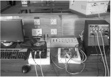
The dSPACE is a real time simulation system that consists of a set of hardware and software as shown in Fig-1. Initially the dSPACE software should be installed in the system. An interface board will be provided with the hardware components which have to be placed in the PCI slot of PC. Through this interface board the CP1104 connector panel will be connected for connection between the external hardware which is shown in Fig-2.
[image:2.595.306.536.94.256.2]Fig -1: Experimental setup of plant with dSPACE
Fig-2: Experimental set up of SRV02
3.
T
HEORITICALT
RANSFERF
UNCTION OFQ
UANSERS
ERVOM
OTORThe angular rate Ωl(s) of the SRV02 load shaft with
respect to the input motor voltage Vm(s) can be described
by the following first order transfer function,
. 1 0.0253s
1.53 (s)
V (s) Ω
m l
The transfer function model is derived analytically from electrical and mechanical equation of the motor which is obtained from first principles.
Thus the Steady state gain of the system is,
. sV rad 1.53 K
Time constant is,
s
0253
.
0
4.M
ODELING OFSRV02
P
LANTE
XPERIMENTALLY [image:2.595.43.275.443.587.2]© 2017, IRJET | Impact Factor value: 5.181 | ISO 9001:2008 Certified Journal | Page 1138 parameters of a model until a reasonable fit is obtained.
The inputs can be chosen in many different ways and there is a large variety of methods. The Frequency response method is discussed.
4.1
Frequency response method
In this method a sine wave input with a set amplitude and frequency is given to the servo motor. The output will be sinusoid with the same frequency but with different amplitude. By varying the frequency of the sine wave and observing the resulting outputs, bode plot of the system can be obtained. From bode plot the steady state gain, i.e. the DC gain, and the time constant of the system can be determined.
5. REAL TIME EXPERIMENT
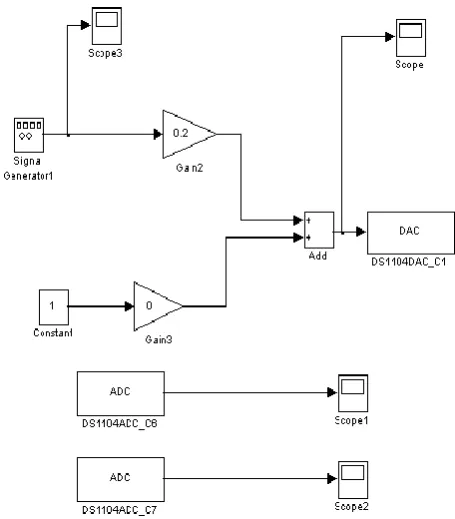
In the Simulink library, the signal generator block is selected and following parameters are ensured:
Wave form: sine Amplitude: 0.0 Frequency: 1.0 Units: Hertz
The Amplitude (V) slider gain is set to 0.0V. The offset (V) block is set to 0.2V.
Input is given to the DC motor through DS1104 DAC channel1.
Response from the motor is obtained from DS1104 ADC channel6.
Speed of DC motor is obtained from DS1104 ADC channel 7.
Now the MATLAB file will be transferred to dSPACE environment by selecting incremental build option.
[image:3.595.326.554.97.357.2]When this input is given to the SRV02 unit it should begin rotating in one constant direction. Then the offset is set to 0.0V and slider gain is set to 0.2V.
Fig-3: MATLAB diagram for modeling the DC servo motor
[image:3.595.336.537.417.554.2]
Fig-4: Frequency response of system
6. Response of the system
By varying the frequency of the sine wave input maximum speed of motor shaft is calculated and corresponding gain values are obtained which is given in table 1.
© 2017, IRJET | Impact Factor value: 5.181 | ISO 9001:2008 Certified Journal | Page 1139 Table -1:
Collected Frequency Response Data
Frequ ency
(Hz)
Input (V)
Max load speed (rad/s) Gain: (rad/s/V) Gain (dB)
0 0.2 0.3369 1.6845 4.52
1 0.2 0.3247 1.6235 4.20
2 0.2 0.3228 1.6140 4.16
3 0.2 0.2832 1.4160 3.02
4 0.2 0.2637 1.3185 2.40
5 0.2 0.2466 1.2330 1.82
6 0.2 0.2275 1.1375 1.14
7.
TRANSFER FUNCTION
Magnitude of Frequency response of SRV02 plant transfer function, . (0) V (0) Ω (0) G m l v wl,
where, ω is the frequency of the motor input voltage. Thus for f=0Hz the maximum load speed is 0.3369 and the voltage is 0.2V. Therefore Gain is,
. sV rad 1.6845 (0)
Gwl,v
The Gain in dB is,
dB. 4.52 6845) 20log10(1. (0) G dB vwl,
The -3dB Gain is,
dB. 1.52 ) (ω G dB c v wl, From the bode plot the cut-off frequency is fc=6.6 Hz.
c=2πfc.
. s rad 41.469
ωc
Time constant is,
. ω 1 τ c 0.024s. τ
Thus the transfer function of the system is,
. 1 0.024s 1.52 (s) V (s) Ω m l
8.
SRV02
POSITION
CONTROL
8.1.
SRV02 Position Control Specifications
The time domain specifications for controlling the position of the SRV02 load shaft are,
ess=0 (11)
tp=0.2[s] (12) PO=5[“%”] (13)
Thus when tracking the load shaft reference, the transient response should have a peak time less than or equal to 0.2 seconds, a over shoot less than or equal to 5% and the steady state response should have no error.
Calculate the maximum overshoot of the response (in radians) given a step set point of 45degrees, or
4
π
t
θ
d
(14)Using the expression,
100
PO
1
t
d
θ
p
t
θ
(15)The maximum overshoot with a step response of,
0.785[rad]
(t)
θ
d
(16)
t
0.823[rad]
© 2017, IRJET | Impact Factor value: 5.181 | ISO 9001:2008 Certified Journal | Page 1140
8.2.
PV Control Design
The proportional-velocity (PV) Compensator used to control the position of the SRV02 has the structure,
t
l
θ
dt
d
v
k
t
l
θ
t
d
θ
p
k
(t)
m
V
(18)Where kp is the proportional control gain, kv is the velocity
control gain,
d
t
is the set point of reference load angle, and
l
t
is the measured load shaft angle, and Vm is the SRV02 input voltage.Fig-5: Matlab Model For Position Control of The Servo Motor using PV
This control multiplies error by proportional gain and differentiates the output which gives velocity. It is then multiplied by velocity gain and added for generating control input.
Fig-6: Response of PV Control
Fig-7: Response of PV Control IndSPACE
8.3.
PIV Control Design
Fig-8: Matlab Model For Position Control Of The Servo Motor using PIV
Adding an integral control can help to eliminate any steady state error. It also suppress spike due to velocity feedback. System response can be improved by integrating the error.
© 2017, IRJET | Impact Factor value: 5.181 | ISO 9001:2008 Certified Journal | Page 1141 Fig-10: Response Of PIV Control IndSPACE
Since the Quanser Servo motor is a non-linear system theoretical design of transfer function and controller which is a black box approach will not support in accurate control of the plant. The transfer function that is derived practically is utilized to develop the PV and PIV controller for position control of the Quanser servo motor. The experiment is carried out to check the response of the PV and PIV controller, which had greatly minimized the steady state error and peak over shoot of the Quanser Servo motor.
9.
CONCLUSION
The experiment to derive the transfer function of Quanser Servo motor is carried out with the help of dSPACE software. Input to the system is given through the DS1104 board and the response of the system is recorded using the dSPACE software. The interfacing procedure of SRV02 plant with UPM, dSPACE hardware and software is clearly explained.
Thus from the recorded data transfer function of the Quanser servo plant is experimentally determined using Frequency response method
The following advantages of using the DS1104 controller board for implementation were seen
a) Less time require for implantation of different control algorithm.
b) Reconfigurability.
c) Less external passive components. d) Less sensitive to temperature variation. e) High efficiency.
f) Higher reliability and flexibility.
The response of PV and PIV control were compared.
DESCRIPTION SYMBOL VALUE UNIT
NOMIANL VALUES Open loop steady-state
Gain K 1.53 rad/s/V
Open loop time
constant
0.0253 sFREQUENCY RESPONSE MODELING Open loop steady-state
Gain Ke,f 1.52 rad/s/V
Open loop time
constant
e,f 0.024 sA
CKNOWLEDGMENTThe authors wish to thank the College Management and Principal for being a constant source of encouragement and providing the facility to utilize the dSPACE S/W & H/W and Quanser make module in Thiagarajar College of Engineering, Madurai.
R
EFERENCES[1] Quanser consulting, “QUANSER DS1104 INTERFACE
BOARD”, 2002.
[2] Quanser . “SRV02 MODELING USING QUARC”.
[3] Nicanor Quijano and Kevin M. Passino, “Modelling and
System Identification for a DC Servo”, Deptartment of Electrical Engineering, The Ohio State University, March 29, 2002.
© 2017, IRJET | Impact Factor value: 5.181 | ISO 9001:2008 Certified Journal | Page 1142
[4] Nicanor Quijano and Kevin M. Passino, “Interfacing
dSPACE to the Quanser Rotary Series of Experiments (SRV02ET)”, Dept. of Electrical Engineering, The Ohio State University, March 22, 2002.
[5] Xiaoou Li and Wen Yu,“Synchronization of Ball and
Beam Systems with Neural Compensation”, International Journal of Control, Automation, and Systems,pp.491-496,2010.
[6] J. Hauser, S. Sastry, and P. Kokotovic, “Nonlinear
control via approximate input-output linearization: ball and beam example,” IEEE Trans. on Automatic Control, vol. 37, no. 3, pp. 392-398, 1992.
[7] Saul Jimenez and Wen Yu, “Stable Synchronization
control for two Ball and Beam systems”, Department of Automatic control, ICEEE, 2007.
[8] N. Quijano, K. M. Passino, EE758 Control Laboratory II:
Lab4(http://www.eleceng.ohiostate.edu/~passino/ee 758.html). 2002.
[9] Quanser . “SRV02 POSITION CONTROL USING QUARC”.
APPENDIX I
SYMBOL DESCRIPTION VALUE
Vnom Motor input
nominal voltage
6.0V
Rm Motor armature resistance
2.6Ω
Lm Motor armature
inductance
0.18mH
kt Motor torque
constant
7.68E-03N.m
m
η
Motor efficiency 0.69Km Back emf constant 7.68-03 V/(rad/s) Jm,rotor Motor shaft
moment of inertia
3.90E-7 kg-m2
g
η
Gear box efficiency 0.9Kg Total gear box ratio 14
Jeq Equivalent moment of inertia
9.76E-05kg-m2
Beq Viscous damping coefficient
0.015N.m(rad/s)
mmax Maximum output load shaft
5kg
fmax Maximum Input
voltage frequency
50Hz
max
ω
Maximum motorspeed
628.3rad/s
Imax Maximum input
current