A Study on the Discharge Characteristics of Discharge
Element with Control Electrode
Keun-Seok Park1, Young-Chan Kim2, Dae-Dong Lee3, Ki-Chan Kim3,*
1Department of Southwestern, Research Institute of Medium & Small Shipbuilding, South Korea 2Department of Technical Engineering, Korea Surge LAB, South Korea
3Department of Electrical Engineering, Hanbat National University, South Korea
Copyright©2019 by authors, all rights reserved. Authors agree that this article remains permanently open access under the terms of the Creative Commons Attribution License 4.0 International License
Abstract
Background/ Objectives: Power system control systems are constantly exposed to surge voltages. These surge voltages cause malfunction of elements controlled by a low voltage such as a CPU and a semiconductor. Methods/ Statistical analysis: A control circuit is constituted by utilizing a discharge element with control electrode and a surge voltage is applied to the control circuit to measure and analyze the discharge voltage that accompanies the capacity change of the current limiting element, transformer, etc. As a result, the effectiveness of the discharge device with control electrode and the control circuit was confirmed. Findings: The capacitance of the capacitor was selected as 0.01uF, 0.1uF, 1uF and the winding ratio of the transformer was set to 15: 1. Then, the impulse voltage of 500 V was injected and the discharge voltage was confirmed. The capacitor 1uF with the lowest discharge characteristic among the capacitors was applied and the test results for the winding ratio of 15: 1 and 20: 1 were confirmed. Applying a 1kV surge voltage to a GCA control circuit with a 1uF capacitor and a 20: 1 transformer, it was confirmed. Through this test, it was confirmed that GCA control circuit can be applied to high surge voltage and maintain low discharge voltage.Improvements/ Applications: In this paper, we study various characteristics of Gate Control Arrestor (GCA) with control electrode and we will use it appropriately in various industries.
Keywords
Discharge Element, GCA, SPD, Surge Voltage, Transient1. Introduction
Recent industrial technology has required not only data that can increase productivity but also control technology that controls parameters based on the data acquired in the use environment and analysis technology capable of quickly analyzing and applying a large amount of data. The
automatic control technology has been developed from the digital electronic control system using PLC to the semiconductor control system using the computer & communication device, so that ultra-high-speed control and precision control have become possible[1]. However, computer and semiconductor devices controlled with a low voltage of less than 3.3 V can cause malfunction or breakage due to various noises and surge voltages, or cause direct or indirect damage. Types of surge voltages include oscillatory impulse, transient voltage, reverse voltage, etc. The cause of the surge is caused by the switching surge of the power converter, the switching surge of the circuit breaker, known for surge startup and stop surge of rotating equipment[2]-[4]. In order to prevent accidents caused by surge voltage, IEC 61643 specifies the performance of the surge protector, test method, requirements, etc[5]. Various surge protectors have been developed and used according to the demands of consumers and the specifications of protected equipment. A typical surge protector is composed of a discharge element such as an arrestor, a varistor, a discharge tube, a Zener diode, and a current limiting element such as a resistor, a capacitor, and a reactor. A typical surge protective device has excellent performance in high level transient voltage but it has low performance in low transient voltages. even with IEEE 1100-2005, it is recorded "May or May not" [6],[7].
In this paper, we study various characteristics of discharge element (GCA , Gate Control Arrestor) with control electrode and verify the performance through experiments, and propose a design technique that can be effectively used in various fields [13].
2. Materials and Methods
2.1. A Discharge element with Control Electrode
tube.
Figure 1. Composition of GCA
In a general gas discharge tube (GDT), when a surge voltage higher than the discharge voltage is applied between the discharge electrodes, a glow discharge is generated due to ionization of the discharge gas sealed inside. This glow discharge generates an arc and instantly removes the surge voltage. When a surge voltage of 100 V is incident on the gas discharge tube, it discharge at about 90 V level, but when the surge voltage of 1000 V is incident, it has discharging characteristics discharge at 700 V level. In this way, GCA was developed in order to solve the problems of the prior art in which the discharge voltage varies according to the incident speed and the magnitude of the surge voltage [12]-[8].
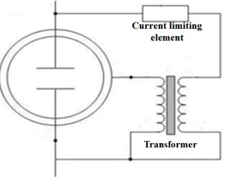
Figure 2. Control Circuit of GCA
As shown in Fig. 2, The GCA control circuit is composed of a current limiting element and a transformer
between the discharge electrode and the control electrode. This circuit amplifies the rapidly incident transient voltage early in the rise and it cuts off when the transient voltage is low point. In addition, the external control electrode builds a magnetic field inside the tube in the dielectric properties of the ceramic material, promotes electronic polarization and induces discharge [11]. The greatest advantage of GCA will be that it is possible to design discharge voltage according to the type of current limiting element, capacity, turn ratio of the transformer.
2.2.Test Method
Applied surge voltage is the standard surge voltage of
1.2/50 μs required by IEC C62.41 and the test method required by IEC61643-11 was applied. The 1.2/50 μs surge
voltage is very similar to the normal surge voltage except for the lightning, so it is easy to check the discharge characteristics of the discharge device[9]-[10].
The magnitude of the surge voltage was 500 V, which is the surge voltage criterion of the AC 220 V surge protector, and the magnitude of the discharge voltage was confirmed using a 1/1000 high voltage probe.
[image:2.595.62.281.79.238.2]The test equipment and circuit are shown in Table 1 and Figure 3.
Table 1. Detail of test equipment
Equipment Model Serial No. Effective Date of Calibration Impulse
Generator SL-6120 SL-6120-0001 2019.08.08. Oscilloscope LC534L 1369 2019.08.08. High Voltage
Probe HVP-28HF 20172286 2019.08.08.
Figure 3. 1.2/50 μs wave
[image:2.595.110.537.398.748.2] [image:2.595.95.255.425.552.2]3. Discharge Characteristics of GCA
3.1. Discharge Characteristics according to Capacitor Capacity
Capacitors are most commonly used as current limiting devices in the surge protector control circuit because
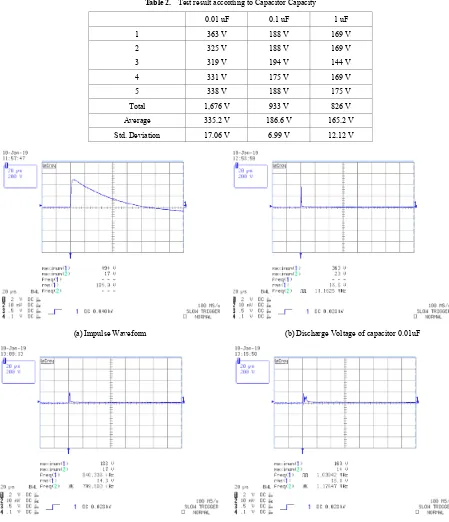
[image:3.595.67.516.178.700.2]capacitors can absorb & compensate for unstable noise in the circuit. The capacitance of the capacitor was selected as 0.01uF, 0.1uF, 1uF and the winding ratio of the transformer was set to 15: 1. Then, the impulse voltage of 500 V was injected and the discharge voltage was confirmed. Injected impulse voltage is shown in Fig. 4 and the test results are shown in Table 2.
Table 2. Test result according to Capacitor Capacity 0.01 uF 0.1 uF 1 uF
1 363 V 188 V 169 V
2 325 V 188 V 169 V
3 319 V 194 V 144 V
4 331 V 175 V 169 V
5 338 V 188 V 175 V
Total 1,676 V 933 V 826 V Average 335.2 V 186.6 V 165.2 V Std. Deviation 17.06 V 6.99 V 12.12 V
(a) Impulse Waveform (b) Discharge Voltage of capacitor 0.01uF
(c) Discharge Voltage of capacitor 0.1uF (d) Discharge Voltage of capacitor 1uF
As shown in Table 2, it was confirmed that the change in the capacitance of the capacitor greatly affects the discharge characteristics of the GCA control circuit. The average value of the discharge voltage by capacitor capacity was measured. As a result, the capacitor 0.1uF was discharged about 148V lower than capacitor 0.01uF and the capacitor 1uF was discharged about 170V lower than capacitor 0.01uF. This surge voltage is of sufficient magnitude to malfunction or destroy common electrical and electronic products and automatic control circuits. Therefore, it is necessary to study the possibility of discharging at a lower voltage when a surge voltage is
incident
3.2. Discharge Characteristics according to Change of Winding Ratio
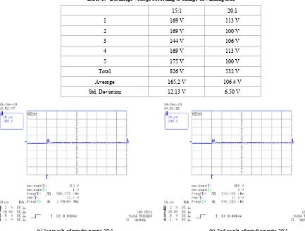
[image:4.595.69.502.242.570.2]In order to lower the magnitude of the discharge voltage in the GCA control circuit, there is a method of adjusting the winding ratio of the transformer installed between the control electrode and the current limiting element. The capacitor 1uF with the lowest discharge characteristic among the capacitors was applied and the test results for the winding ratio of 15: 1 and 20: 1 were confirmed [14].
Table 3. Discharge voltage according to change of winding ratio
15:1 20:1
1 169 V 113 V
2 169 V 100 V
3 144 V 106 V
4 169 V 113 V
5 175 V 100 V
Total 826 V 532 V
Average 165.2 V 106.4 V Std. Deviation 12.13 V 6.50 V
(a) 1st result of winding ratio 20:1 (b) 2nd result of winding ratio 20:1
As shown in Table 3, in GCA Control circuit, it was confirmed that the 20:1 type was discharged about 106 V and 15:1 type was discharged about 165 V. As a result, it is considered that the winding ratio of the transformer in the GCA control circuit also greatly affects the discharge characteristics. Therefore, setting the winding ratio of the transformer in the GCA control circuit can be utilized as a design method of the discharge voltage of the surge protective device. So the magnitude of the discharge
voltage was confirmed by applying 1 kV surge voltage
3.3. Discharge Characteristics against 1kV Surge Voltage
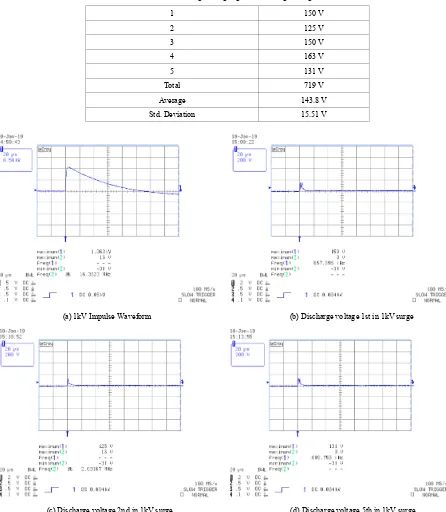
[image:5.595.70.516.213.725.2]Although the GCA control circuit has excellent performance, it is necessary to check the change rate of the discharge voltage to the surge voltage change because the surge voltage is generated in various environments & magnitude.
Table 4. Discharge voltage against 1kV surge voltage
1 150 V
2 125 V
3 150 V
4 163 V
5 131 V
Total 719 V
Average 143.8 V
Std. Deviation 15.51 V
(a) 1kV Impulse Waveform (b) Discharge voltage 1st in 1kV surge
(c) Discharge voltage 2nd in 1kV surge (d) Discharge voltage 5th in 1kV surge
As a result of applying a 1kV surge voltage to a GCA control circuit with a 1uF capacitor and a 20: 1 transformer, it was confirmed to discharge at an average of 143V as shown in Table 4. Through this test, it was confirmed that GCA control circuit can be applied to high surge voltage and maintain low discharge voltage.
4. Conclusions
With the development of high-speed precision control technology, the necessity of surge protector is increasing, and it is used in various fields such as power, control, and communication. The surge protective device used in each industry requires a design technique because the required voltage protection level varies depending on the voltage range of the control device and the allowable voltage range of the control device.
In this paper, the applied GCA control circuit alone is insufficient in the withstand capacity of the discharge circuit to limit the surge voltage of various capacity and size generated in the industrial environment. So the discharge voltage can be limited via GCA control circuit and the capacity of SPD can be increased with parallel design of ZnO varistor, zener diode, TVS diode etc. And if an LC delay circuit such as a reactor or a capacitor is combined, it will be possible to develop a surge protective device that can effectively discharge while delaying the incidence of the surge voltage. The most important technology of the GCA control circuit is that it allows detailed discharge voltage design. If a high-performance surge protective device combined with a GCA control circuit, various types of current limiting elements and discharge elements, LC delay circuits, etc. is developed, the Oscillatory, Transients, and Voltage Spike components included in the power supply wave will be effective. Can be controlled in a controlled manner, and the effect of improving the quality of power and increasing the life of the system can be expected.
REFERENCES
[1] Sung Ju Park. A study on the Surge Protection of Shipboard Electrical and Electronic Devices, HMOU, Master’s degree, 2010
[2] Jong Yun Chea, Dong Jin Kim, Gi Sik Lee and Kyung Wan Koo. The development of parallel type Surge Protector Device for Communication line. KIEE. 2014 Nov; pp242-243
[3] Kostas Samaras. Electrical Surge-Protection Devices for Industrial Facilities-A Tutorial Review. IEEE Transaction on Industry Applications. 2007 Jan./ Feb; 43(1):151-161. [4] Bok-Hee Lee, Bong Lee, Su-Bong Lee, and Sung-Man Kang.
Effects of Lightning Surges on the Life of ZnO Varistors.
KIEE. 2006 May;55(5):257-262.
[5] IEC61643-11, Low-voltage surge protective devices-Part11:Surge protective devices connected to low – voltage power systems-Requirements and test methods [6] Pérez-Luna, Y. C., Sánchez-Roque, Y., & Berrones
Hernández, R. Physicochemical Characterization of Compost Mixtures Enriched with Agroindustrial Waste. Canadian Journal of Agriculture and Crops. 2018 3(1); 33-41.
[7] Mukadasi, B. Mixed Cropping Systems for Sustainable Domestic Food Supply of the Smallholder Farming Communities in Nakasongola District, Central Uganda. Canadian Journal of Agriculture and Crops. 2018 3(1); 42-54.
[8] Islam, S., Hamid, F. S., Shah, B. H., Khan, N., Ahmad, F., & Aftab, S. Response of Organic & Inorganic Fertilizers to the Growth, Yield and Soil Nutrient Status in Tomato (Lycopersion esculentum). Open Academic Journal of Advanced Science and Technology. 2018 2(1); 1-4. [9] Hamid, F. S., Ahmad, F., & Ahmad, N. Impact of Various
Levels of Nitrogen and Phosphorus on Growth and Yield of Spinach (Spinacea oleracea L.) under Conditions of Mansehra (Pakistan). Open Academic Journal of Advanced Science and Technology. 2018 2(1); 5-8.
[10]IEEE 1100-2005, IEEE Recommended Practice for Powering and Grounding Electronic Equipment, 2005 [11]H. K. Shin, D. S. Kim, Y.K. Chung, and B. H. Lee. Energy
coordination of ZnO varistor based SPDs in surge current due to direct lighting flashes, Proc, 2014 ICLP, pp1342-1346, 2014
[12]Keun-Seok Park, Jun-woong Choi, and Dae-Dong Lee. A Study on the Design of Discharge Voltage of Discharge Element with Control Electrode. KIEE. 2018 Nov;67(11):1512~1516.
http://www.dbpia.co.kr/Article/NODE07553277
[13]IEEE C62.45, IEEE Recommended Practice on Surge Test for Equipment Connected to Low-Voltage AC Power Circuit, 2002