Isolation Optimization Method on the Coupler
Yudi Barnadi
*, M. Rozahi Istambul, Ajeng Mayang K S, Savitri galih
Widyatama University, Malaysia, Indonesia
Copyright©2019 by authors, all rights reserved. Authors agree that this article remains permanently open access under the terms of the Creative Commons Attribution License 4.0 International License
Abstract
In this type of radar pulses only have one antenna that is used to transmit and receive signals, it requires a duplexer that will function as a separator for both signals, this duplexer will isolate the transmitted signal and the received signal. The main component of the duplexer that plays a role in the regulation of isolation is the Coupler which is abbreviated as coupler. The performance of the Coupler can be seen from the characteristics of the parameters it has, namely: Isolation Characteristics, Insertion Loss, Return Loss, and Power Coupling. In this study, changes in the dimensions of the Coupler, changes in this size will affect the value of the isolation. If the isolation value gets smaller, the duplexer performance will be better. Coupler in this study is applied in the form of microstrip and substrate used FR-4 with a dielectric constant of 4.6, 1.3 mm thick and 3 GHz operating frequency. To do this work is done with the 2014 CST simulation software, from the results of simulation experiments obtained the isolation value of -67.786 dB.Keyword
Coupler, Duplexer, Isolation, Pulse Radar1.Introduction
The Coupler is a four-terminal passive device that has 4 symmetrical linear arms to produce an output signal that is different in phase 90 [1]. An ideal Coupler will have a matching condition, not having losses (lossless) and reciprocity, its performance is determined by: return loss, insertion loss, coupling factor and isolation. Couplers are part of the Duplexer, and this duplexer is one part of the pulse radar. Pulse radar only has one antenna, the antenna used to transmit and receive signals is the same antenna. In [2] the duplexer has the ability to separate the transmitted signal and the received signal.
The conventional Coupler generally has a fairly large dimension and has an isolation value of <-20 dB at high frequencies with this isolation characteristic cannot be used because of the many signals with different phase angles [3]. The purpose of this study is to obtain a better Coupler isolation value which is smaller than <-55 dB.
In other studies a parallel type of microstrip coupler has been widely used because it has a simple and it is easily to made shape [3]. The weakness is the lack of good isolation and directivity values
In [4] the technique is done by adding the apperture ground plane, this method can improve the isolation of the conventional coupler, but because of the difficulty of fabrication, and this technique cannot be done in the form of MMC. -junction Coupler and it produces an isolation value of -55 dB. In [5] used two diode capacitance variables in the circuit that are useful as tuning to obtain the desired working frequency, from the simulation results obtained an improvement of isolation of - 52 dB [6]. In [3] size reduction, weight but has a higher level of integration and lower power consumption as in [7] in the form of Monolithic Microwave Integrated-Circuit (MMIC) and thin-film multichip module technology (MCM-D ) [8] integrated into microstrip [6] and T / R swiching circuit [9]. For this purpose a design is needed that is integrated between active and passive components. But the method of integrating the above components produces a low isolation below -20 dB.
In [10] a coupler is used as a separator between the sender and the receiver, the antenna that sends and receives signals that have a different polarization. Modification process of the coupler dimensions at T junctions with
physical parameters W50 Ω: 2,952 mm, L50 Ω: 15.2 mm
and W35, 35 Ω: 5, 14 mm, L 35,35 Ω: 15.2 mm from the simulation results obtained isolation values - 31,185 dB. In [12] a patch-coupled directional coupled patch which has an ellip-shaped patch with an arm length of 22.5 mm, is used Ro Rogers substrate 4003C 3.38 dielectric constant at a working frequency of 2 GHz obtained an isolation value of -45 dB.
In this study, FR-4 is used because it is easily obtained in the market, to obtain best is the result of the optimization of the transmission coupler channel by modifying the length and width of the series arm (Zo = 50 Ω), the length and width of the series arm (Zo = 35.35 Ω), the length and width of the parallel arm (Zo = 50 Ω) to do the optimization.
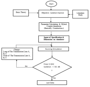
Figure 1. Flow chart optimization of the Coupler
2. Research Methodology
The design at the Coupler is performed to obtain a good performance, the coupler works at 3 GHz operating frequency and is implemented on the S band frequency
.
There are several steps to design this Microstrip Coupler which is to determine the specifications of the coupler, determine the substrate to be used, the design of the coupler geometry is designed and then calculate the microstrip physical parameters designed using the formula for microstrip design. Then simulated using Computer Simulation Technology (CST) 2014 Software.
2.1. Determine the Specifications of the Coupler
The initial step in the design is to carry out the specifications of the coupler that will design. The design of the coupler is to get isolation characteristics that are better than -55 dB, operating frequency 3 GHz. Coupler for this design has the following specifications:
Frequency: 3 GHz Material: FR-4 (Efoxy) Permitivitas (𝛆𝛆r): 4, 6 Thickness (h): 1, 3 mm Copper thicknes: 0.035 mm Light speed (c): 3x108 mm/s
Z0: 50 ohm 𝑍𝑍𝑍𝑍/√2 : 35,35 ohm
Vswr: < 1,5 Isolation: < -55 dB
This Coupler is designed at 50 ohms impedance.
Therefore, the quarter wavelength portion of the device has an impedance of 50 ohms and 35.35 ohms. The coupler will be made from microstrip on FR4 (Epoxy) substrate. For the first design, the length and width of the transmission line is calculated using the formula in [3]
A. Calculation
In this research studies, the substrate used type FR 4, determines the wavelength (λg) which propagates on the material used. The wavelength propagating in the material has the following equation [5, 16]:
𝝀𝝀g = f × c√εr (3.1)
𝝀𝝀g = (3 ×103 ×910) × 8
√4,6= 0,04612 m = 46,63mm
From the calculation, the wavelength (λg) obtained is
46.63 mm.
𝜆𝜆𝜆𝜆=464,12= 11,66 𝑚𝑚𝑚𝑚, then the long AP=BP=CP
=11,66 mm
To determine the width can be calculated [5] :
𝑊𝑊
𝑑𝑑 =
8𝑒𝑒𝑎𝑎
𝑒𝑒2𝑎𝑎−2 (3.2) where Zo is 50 Ω :
𝑎𝑎= 𝑍𝑍0
60�
𝜀𝜀𝑟𝑟+1
2 +
𝜀𝜀𝑟𝑟−1
𝜀𝜀𝑟𝑟+1 �0.23 + 0.11
[image:2.595.207.506.77.364.2]𝑎𝑎= 5060 �4,6 + 1 2 +
4,6 −1 4,6 + 1 �0.23 +
0.11 4,6 �
𝑎𝑎= 1,56
𝑊𝑊 𝑑𝑑 =
8𝑒𝑒𝑎𝑎
𝑒𝑒2𝑎𝑎−2 𝑊𝑊
𝑑𝑑 =
8𝑒𝑒1,61
𝑒𝑒2.1,61−2 𝑊𝑊
𝑑𝑑 = 1,845 , d=1, 30 mm,
𝑤𝑤= 1,845𝑥𝑥 1,30 = 2,398 mm
𝐴𝐴𝐴𝐴=𝐵𝐵𝐴𝐴= 2, 398 𝑚𝑚𝑚𝑚
If zo= 35, 35 Ω
• 𝑎𝑎= 35,3560 �4,6 +12 + 4,6 +14,6 −1 �0.23 +4,60.11�= 1,149
• 𝑊𝑊
𝑑𝑑 =
8𝑒𝑒1,149
𝑒𝑒2.1,149−2= 3,173
• 𝑤𝑤= 3,173 𝑥𝑥 1,3 = 4,125 𝑚𝑚𝑚𝑚
[image:3.595.54.260.76.325.2]Then CL= 4,125 mm, the value of transmission line AP = BP =CP = 11,66 mm, AL = BL = 2,398 mm dan CL = 4,125 mm
Tabel 1. The size of the transmission line from the calculation results
[image:3.595.325.508.167.314.2]From table 1. length of transmission line A (AP) = 11.66 mm, length of transmission line B (BP) = 11.66 mm, length of transmission line C (CP) = 11.66 mm, width of transmission line A (AL) = 2,398 mm, width of transmission line (BL) = 2,398 mm, width of transmission line C (CL) = 4,125 mm.
Figure 2. Design of the Coupler
Where are the abbreviations as follows: AP = Length of transmission line A (mm) BP = Length of transmission line B (mm)
CP = Length of transmission line C (mm) AL = width of the transmission line A (mm) BL = width of the transmission line B (mm) CL = width of the transmission line C (mm)
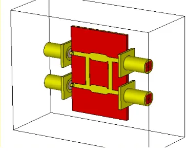
[image:3.595.71.280.396.506.2]Figure 3. Shows the layout of the Coupler construction obtained from the simulation.
Figure 3. Construction of the Coupler
3. Research Method
This research begin with a calculation of the dimensions of the conventional BLC formula. This initial design calculation will be examined in the simulation. Modification on BLC dimensions is conducted as a way to obtain optimum results in simulation, then the optimum design will be fabricated. The BLC is designed using 90° Hybrid Coupler, with a resonant frequency at 3GHz. a. Calculation of the Length of the transmission line
The length (L) of the coupler usually equal to a quarter of wavelength which propagates in material as follow [10, 11]:
𝝀𝝀g = f × c
√εr 𝝀𝝀d = λg4
where f is operating frequency of the coupler, and ɛr is
dielectric constant of the substrate.
b. Calculation of the Width transmission line
𝑊𝑊
𝑑𝑑 =
8𝑒𝑒𝑎𝑎
𝑒𝑒2𝑎𝑎−2
Where Zois 50 Ω and 35,35 Ω
𝑎𝑎= 𝑍𝑍0 60�𝜀𝜀
𝑟𝑟+ 1
2 + 𝜀𝜀𝑟𝑟−1
𝜀𝜀𝑟𝑟+ 1 �0.23 + 0.11
𝜀𝜀𝑟𝑟 �
[image:3.595.60.290.596.691.2]c. Procedure:
The modification of the coupler determines the effect changes in the length and width of the transmission line A, B and C branchline coupler to the isolation value.
1.The length of the transmission line A (AP-1) and B (BP-1) is reduced, but the length of the transmission line C (CP), and the width of the transmission line Al, BL and CL does not change (the same as the value of the calculation result ), this can be seen in table 2.
[image:4.595.64.290.282.375.2]The length of the transmission line A (AP-1) is reduced from 11.66 mm, 11.55 mm, 11.50 mm, 10.50 mm and last 10.35 mm, but the length of the transmission line BP, CP, and the width of the transmission line Al, BL and CL does not change (the same as the value of the results of the calculation), this can be seen in Table 2.
Table 2. Reduction in length of transmission line A
The length of the transmission line A (AP-1) and B (BP-1) is reduced from 11.56 mm, 11.50 mm, 10.50 mm, 10.47 mm and last 10.36 mm , but the length of the transmission line CP, and the width of the transmission line Al, BL and CL does not change (the same as the value of
the results of the calculation), this can be seen in Table 3. Table 3. Reduction in length of transmission line A
[image:4.595.309.533.291.387.2]The length of the transmission line A (AP-2), B (BP-2), C (CP-2) are reduced, but the width of the transmission line A (AL-1), B (BL-1) and C ( CL-1) increases from 4.037 mm, 4.200 mm, 4.800 mm, 5.000 mm, 5.020 and last 5.067 mm. this can be seen in table 4.
Table 4. The Width addition of the transmission line C
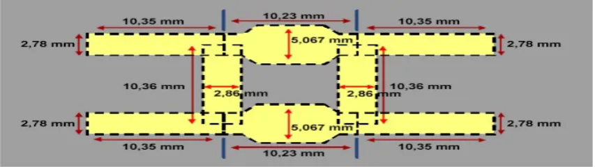
[image:4.595.85.512.465.585.2]And it can be seen in point number 7, the frequency value is at the 3 GHz position optimal dimension with the best isolation value obtained are when AP-1 = 10.35 mm, BP-1 = 10.36 mm, CP-1 = 10.23 mm, AL-1 = 2.78 mm, BL-1 = 2.86 mm and CL-1 = 5.067.
Figure 4. Optimal dimension of Coupler In the picture above shows the dimensions of the coupler optimization results. A. Simulation Result
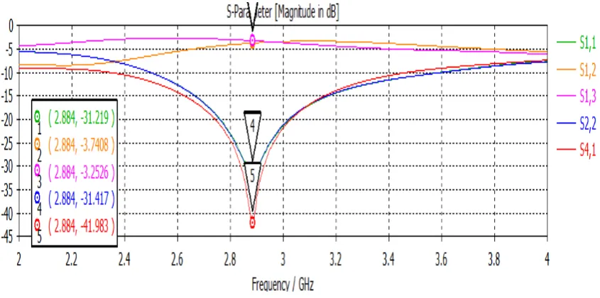
Figure 5. Simulation result from calculation
It can be seen at Figure 5, that the operation frequency is shifted to 2.884 GHz instead of 3 GHz. After optimization is conducted, the result is shown in Figure 6.
[image:5.595.88.514.357.526.2]From the figure 7, The isolation obtained reach -67.786 dB. This is the best value of isolation.
Figure 6. Simulation result s parameter from optimal dimension
B. Comparison dimension calculation and optimization result
The comparison of the dimension of the best isolation BLC with the conventional one can be seen at Table 5.
Tabel 5. Comparison dimensions calculation result and optimization
Variable Calculation (mm) Dimension Dimension (mm) Optimization
AP 11.66 10.35
A:L 2.398 2.78
BP 11.66 10.36
BL 2.398 2.86
CP 11.66 10.23
CL 4.125 5.067
4. Conclusions
The values of the parameter S in the simulation results of return loss (S11) on the coupler is -31.456 dB while the measurement result is -29.032 dB [13]. The isolation value of the measurement result is -64.546 dB and the simulation result is -67.786 dB, phase measurement results obtained -91.66◦ for S13 and S31. This is close to the ideal value is 90◦. VSWR simulation results obtained are vswr1 = vswr4
[image:5.595.60.289.636.744.2]REFERENCES
[1] W-d, Wirth. Radar Techniques Using Array Antennas. IEE, 2001
[2] Vijiyan, G. (2015). Current Trends in Software Engineering Research. Abstract of Emerging Trends in Scientific Research, 3, 1-12.
[3] Byung-Jun Ahn, S.K Kim and J.G Yook, “Isolation-Improved Coupler Based
[4] On Feed-forward Technique” , Dept of Electrical and Electronic Eng.Yonsei Univ. Korea, IEEE 2005
[5] M. Moradian and M. Khalaj-Amirhosseini, “Improvement the Characteristic Of the Microstrip Parallel Couple line Coupler by means of Grooved Substrate”, Dept of Electrical Engineering Iran University of Science and Technology Narmak, M, Vol. 3, 205–215, 2008
[6] M. Moradian,“Improving isolation of slot-coupled directional couplers,” Electronic Letters 11th, vol.51 No.12,pp 914-915, June 2015
[7] Wilems,D. A, “ A boadband MMIC-S quadrature coupler using a braided microstrip structure”, IEEE MTT-S International, Microwave Symposium Digest, vol. 2, pp 899-902, May 1994
[8] S. Banda and H. Ogawa, “ Multilayer MMIC directional couple using thin dielectric layers,” IEEE Trans. Microwave Theory and Tech, vol.43, pp 1270-1275, June 1995
[9] Carchon, G, De Raedt, W. And Nauwelaers, B, “Integration of CPW Quadrature Couplers in Multilayer thin-film MCM-D”, IEEE Trans. Micro-wave Theory and Tech, vol.49,pp 1770-1776, Oct 2001
[10] Kumar, B. S., & Cristin, R. (2018). A Survey on Efficient Power Management Using Smart Socket and IoT. Review of Computer Engineering Research, 5(2), 25-30.
[11] Lukas W. Mayer, Arpad L. Scholtz, “Circularly Polarized Patch Antenna with High Tx-Rx separation”, Vienna Univ of Technology, IEEE. 2009
[12] Riyanti Indah, “Perancangan Microstrip Branch - line Coupler dengan T- Junction untuk Mobile Wimax pada Frekuensi 2, 3 GHz.” Skripsi S1 Universitas Indonesia, 2009.
[13] M. Moradian, “ Improving isolation of slot-coupled directional couplers,” Electronic Letters 11th, vol.51 No.12,pp 914-915, June 2015