A Perceptive Mannequin Flag Operator
Ahmad Yusairi Bani Hashim
Department of Robotics and Automation, Faculty of Manufacturing Engineering, Technical University of Malaysia Melaka, Malaysia
Copyright©2017 by authors, all rights reserved. Authors agree that this article remains permanently open access under the terms of the Creative Commons Attribution License 4.0 International License
Abstract
In road construction, in particular on a bustling highway, an operator is needed to alert the drivers to decelerate the speeding vehicles. In doing so, an operator is asked to stand at a safe place, some distance from the construction site and to wave a small flag. Although the flag is light, prolonged waving flag cause tiredness to the operator. If the operator stops shaking, the safety of his co-workers is at risk. It is a straightforward thinking that replacing a human operator with a robot operator is a good choice while keeping the human-like figure. The presence of a human figure effectively alerts the drivers as compared to object signs or signal lights. This paper presents a robotic, human-like figure that performs a simple one axis controlled flag waving task. It comes with a monocular vision that video streams the oncoming vehicles. A program is written in Python language with SimpleCV module that processes the video data. A signal is sent to the controller upon detecting the approaching vehicles. As a result, the robot operator would move its arm, thus waving a flag as a warning signal. A pneumatically powered actuator drives the arm. The robot operator was tested in a controlled environment where the results showed that it has a potential for field implementation.Keywords
Mannequin Flag Operator, Flagman, Anzen Taro, Monocular Vision1. Introduction
In road construction, in particular, on a bustling highway, an operator is needed to alert the drivers to decelerate the speeding vehicles. In doing so, an operator is asked to stand at a safe place, some distance from the construction site and to wave a small flag. Although the flag is light, prolonged waving can cause tiredness to the operator. If the operator stops shaking, the safety of his co-workers is at risk. It is a straightforward thinking that replacing a human operator with a robot operator is a good choice while keeping the human-like figure. The presence of a human figure effectively alerts the drivers as compared to object signs or signal lights.
In humanoid robot (HR) design practice, certain values need prioritize. Such method includes the notion of safety and security, expressivity, believability, and organic [1]. It is suggested that extrovert, sympathetic, and enthusiastic are the traits that HRs should possess so that they are more efficient in human decision-making [2].
Moreover, HRs with soft tissues are well suited for tasks that heavily involve with the environment, especially in the medical environment where contacts with patients are imminent [3], and are more accepted by humans if they are human-like [4]. Studies suggest that facially expressive robots are effective as therapeutic tools for children with Autism Spectrum Disorder and tend to be more accepted by children if the robots are smaller [5]. It seems that HRs have gained social acceptance. So, it is fair to predict that robots will replace some jobs by 2025 [6].
2. Background
Application of a robot operator is not new. The kind of operator is used in numerous road, and highway construction and repair works. It is known as BOB in Malaysia, Flagman in New York, Anzen Taro in Japan. The BOB (Boneka Operator Bendera—“Mannequin Flag Operator (MFO)”), for example, is developed by UEM Group a corporation that involves in major construction works in Malaysia. BOB’s design is meant to operate regardless of the traffic conditions. Upon energized, BOB waves the flag continuously, if not intervene, until the power supply depletes.
Suppose an instrument is installed to the MFO system that induces signals only when incoming vehicles are detected. Using the signals as input, the MFO would act only when moving objects are approaching. What kind of instruments that suit this idea?
An obvious advantage of a video camera is the ability to deliver data that may be used to identify distinct characteristics of an object. For example, a vision system may be used to seek for signs of body discomfort when monitoring a human operator while working [7]. Based on the recorded video, a human operator may exhibit symptoms of body discomfort deduced from the curves’ patterns of image histograms. [8].
For that reason, a vast majority of HRs in the market have some vision techniques applied for effective perception, in addition to, social acceptance. ZENO R25 is one such robot designed to be used as a social robot. It is a 22-inch high with a 10-pound dynamo robot that is capable of grasping an object, walking, and talking [9]. Another example is the Robovie, a robot stationed in a shopping mall, gains acceptance by visitors as a mascot instead of a utility [10].
Some major cities in the world are embracing the concept of the smart city. A smart city is made of powering, securing, lighting, greening, and transport. There is a rise of autonomous vehicles development and is expected to be found on the roads in the future. The autonomous vehicles, however, should only be used on dedicated roads to avoid accidental collisions [11].
Implementing an MFO in this environment would require a robust HR that should be made to function within the cloud robotics protocols [12]. Indeed, the MFO should possess a level of awareness to the surrounding [13]. Such knowledge, on the contrary, is absent for the robot that guides the traffic in the city of Kinshasa.
3. System Models
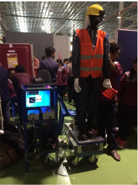
Our MFO is shown in Figure 1. It is a human skeleton model, six feet tall, decorated with construction outfits to achieve human-like figure. A wheeled stand made of steel and aluminum profiles is where the MFO is secured. It also holds pneumatic system and a portable air compressor. A separate rack is where the computer and electrical control modules are placed. A webcam is attached to the hard hat.
The MFO system has four subsystems distinguished by their unique functions and devices used. Subsystem 1 (SS1) represents the electrical controls where all the hard-wiring are realized. Devices used are relays and switches. The system operates on electrical energy.
The overall weight of the system is somewhat heavy. In the occasion of lifting it, four healthy young men would handle the job efficiently. As of the existing MFO design found elsewhere, we do not have access to the weight of the system. We suspect that they are lighter as compared to ours because they only apply a battery with a motor and some linkages and no vision system.
Subsystem 2 (SS2) represents the electro pneumatics where the output torque to swing the MFO’s arm is realized. Devices used are solenoid actuated directional control valves, manually actuated directional control valves, rotary
[image:2.595.313.552.118.439.2]actuator, flow control valves, service unit, air compressor. The system operates on electrical, potential, kinetic energies.
Figure 1. The MFO with construction outfit was exhibited during the Faculty of Manufacturing Open Day on 2 June 2016
Figure 2. The rotary actuator is installed onto a link. A link made of the aluminum profile is attached to the left forearm. Since the model skeleton is fragile, the arm’s pose was adjusted according to the joint flexibility
[image:2.595.314.552.470.651.2]Table 1. List of parts and components whose notations found in Figure 4
№ Notation Description № Notation Description
1 RA Rotary actuator 16 KA-3 Relay 3
2 MANN Robotic mannequin 17 1KA-1 Contact 1 of relay 1
3 FCV-1 Flow control valve 1 18 2KA-1 Contact 2 of relay 1
4 FCV-2 Flow control valve 2 19 1KA-2 Contact 1 of relay 2
5 SOL-1 Solenoid 1 on DCV 20 2KA-2 Contact 2 of relay 2
6 SOL-2 Solenoid 2 on DCV 21 1KA-3 Contact 1 of relay 3
7 DCV Directional control valve 22 STR Start switch
8 EMV Emergency valve 23 STP Stop switch
9 SOV Shut-off valve 24 EMR Emergency switch
10 USB-RS232 USB to RS232 cable 25 VS Video stream
11 COM-OUT Signal from COM port 26 PYTHON Python language
12 GND Computer system ground 27 SIMPLE-CV SimpleCV software
13 INT Interface circuit 28 OP Human operator
14 KA-1 Relay 1 29 CAM Webcam
15 KA-2 Relay 2 30 VH vehicle
System 4 (SS4) represents the arm mechanics where the constraints in the arm are modeled. A device used is the left arm of a human skeleton model. It operates on potential and kinetic energies. Table 1 lists the devices and tools with the respective notations.
3.1. Subsystem 1—Electrical Controls
The electrical control circuit realizes the discrete events of pre-actuators through switches, see Figure 4. These devices accept and provide TRUE or FALSE signal, listed in Table 1 as {KA1, KA2, KA3, STR, STP, EMR}.
The system’s outcome is to energize SOL-1 or SOL-2 but not both at the same instance. The solenoid-actuated DCV would shift position accordingly. The solenoids are energized subject to the system’s logic conditions. The system is in a ready state when the 24-VDC supply is initialized.
Upon depressing the STR, the system would first have the relay KA-1 energized thus conforming to Equation (1). It involves the state of the EMR, STR, STP, and a contact of KA-1.
The state of KA-2, however, depends on the state of KA-1 and KA-3. It is defined in Equation (2).
(1)
(2)
The status of KA-3 depends on the signal from the USB-RS232 port. It is energized as long as the product of the interface circuit gain and the output voltage for the COM port is far greater than zero. It is defined in Equation (3). The solenoids’ state would depend on the state a priori, hence Equation (4).
(3)
(4)
3.2. Subsystem 2—Electro pneumatics
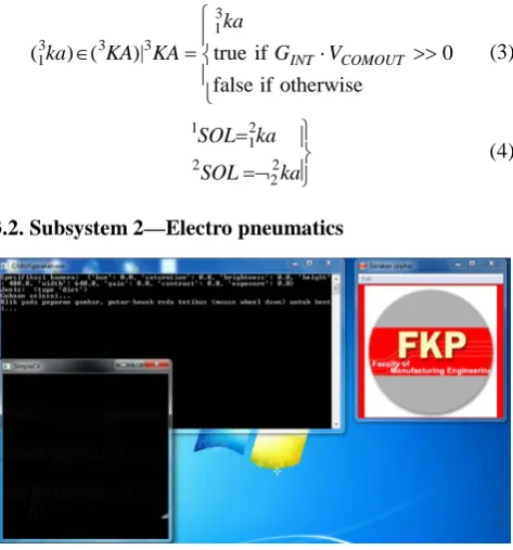
Figure 3. The computer interface was developed using Python language with the vision module, SimpleCV. On the right-hand side is the graphic user interface for system execution. The console on the top left-hand side is the text-based status monitoring window, while below it is SimpleCV graphic window that displays gray scale video data frames
The aim of the electro-pneumatic circuit is to produce rotary motion using a rotary actuator (RA). This movement
(
)
∧ ¬ ∨ ∧ ¬ = ∈
) (
)| ( ) , (
1 1 1
2 1 1 1
1 1 2 1 1
ka STP STR
EMR ka ka
KA KA ka ka
∧ ¬ = ∈
∈
ka ka
ka ka
KA KA ka KA ka ka
3 1 2 1 2 2 2 1 2 3 3 1 2 2 2 2
1 , ) ( ),( ) ( )|
(
otherwise if
0 if
false true )|
( ) (
3 1 3 3 3
1 ⋅ >>
=
∈ GINT VCOMOUT
ka
KA KA ka
=¬ =
ka SOL
ka SOL
2 2 2
[image:3.595.315.552.416.670.2]offers a certain amount of torques allowing the waving motion. The hardware installation is shown in Figure 3. Since the MFO has an active joint, only a rotary actuator is used.
An MFO is designed to work on sites such as the construction and the road traffic areas. It is stationed alone and away from the pedestrian. The decibel level in busy road traffic is somewhat within around 70 dB [14]. The noise level produces by the pneumatic devices is as much as the road traffic’s noise level. The issues of noise and vibration levels produced by the MFO are negligible because the surrounding is already noisy.
[image:4.595.345.555.249.360.2]Devices applied in this system accept and deliver clean, compressed, and regulated air pressure and flow. With proper and careful tuning, the result is the RA oscillates back and forth. From Table 1, the devices are represented as {RA, DCV, FCV1, FCV2, EMV, and SOV}. They can be found in Figure 4, naturally stated in the electro-pneumatic circuit.
The RA’s direction of rotation subjects to the logic state of the upstream devices. Upon initializing the air compressor, the compressed air is stored in a tank until enough pressure has built up. As the pressure is released to channels, the downstream flow (q) and pressure (p) develop. With p and q existing, the system is in a ready state.
When RA has enough pressure builds up with sufficient flow, by definition of Equation (5), it would either rotate clockwise (CW) or counter-clockwise (CCW). It produces CW and CCW oscillation. For the RA to work well, some logic expressions must be attained. These are expressed in equations (6), (7), (8), and (9).
(5)
(6) (7)
(8)
For some tuned pressure, there should exist flow if the port of the valve is unblocked. So, torque in the CW direction should establish and control via SOV, EMV, DCV, FCV1, and FCV2. The torque for the CCW direction of rotation works in a similar fashion. The DCV, on the other hand, is dependent upon the status of SOL1 and SOL2.
(9)
3.3. Subsystem 3—Computer Interface
[image:4.595.72.546.482.692.2]The computer interface subsystem handles the process for decision making which task is to determine the presence of incoming objects. The captured video frame data shall be treated by special algorithms written in Python scripts with SimpleCV module. Figure 4 describes the user interface, monitoring, and video streaming windows upon executing the program.
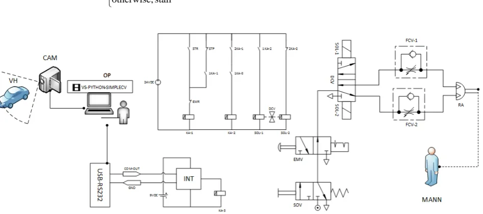
Figure 4. The overall system architecture for the MFO. The explains how video data frame is processed by a dedicated Python-SimpleCV application that sends signals upon detecting the approaching vehicles. Through USB-RS232, the signals are amplified by the INT that later energizes KA-3, which in turns activate RA. As a result, the MANN waves the flag
= =
∈ + −
stall otherwise,
true false, if CCW
false true, if CW } , { )
(ra RA RA ra ra
[
]
pqA FCV dcv
EMV SOV
ra q
p, ) 0 ,
( ≠ = ∧¬ ∧ ∧
∃ + +
[
]
pqB FCV dcv
EMV SOV
ra q
p, ) 0 ,
( ≠ = ∧¬ ∧ ∧
∃ − −
SOL SOL
SOL SOL
dcv dcv DCV DCV
dcv 2 1
2 1
) (
∧¬ =
∧¬ =
=
∈ −+
∧ =
∧ =
=
= ∈
+ −
− + − −
+ +
fcv fcv FCV
fcv fcv FCV
fcv fcv
fcv fcv
FCV fcv
B A
2 1
2 1 2 1
2 1
function no
false,
flow restricted denotes
true, ,
function no
false,
flow free denotes true, ,
The user interface has one menu bar “Fail” (File) that contains three sub-commands used to initialize, end, and quit the application. If the COM port and the Webcam are identified and are working properly, then the application initiates two pop-ups: console, and SimpleCV graphic windows. It is expressed in Equation (10).
(10) Let individual frame of a video frame data denoted as fi. Suppose a threshold is set to determine if there exists the difference of the streaming frame data. At an instance, if there is a difference between two data sets such that the average difference is larger than the threshold (h) then the camera records video data frames of the approaching vehicles. The conditions are expressed in Equation (11) and Equation (12).
(11)
(12)
3.4. Subsystem 4—Arm Mechanics
The arm mechanics dictates the constraints to the mechanic of swinging. Suppose that the prior subsystems function well, the MFO’s arm is now ready to do the work. The required load torque (ML) must overcome the opposing moments where RA is closely mounted, which defined in Equation (13). It defines the generalized load moment delivered by the RA; where ∆v is the volume difference, J is the reduced moment of inertia, bω is the viscous friction coefficient, MF is the resistance torque, Φ is the angle of rotation. With sufficient pressure differentials, the load torque can overcome the resistances. As a result, the arm swings.
(13) There are two possibilities in regards to vector direction. It is expressed in Equation (14) where the load moment may have a CW or CCW direction of rotation. Equation (15) and Equation (16) specifically introduce the angle of rotation either in the CW or the CCW direction as expressed in Equation (17). With that, Equation (18) defines the arm oscillation by the MFO. Hence alert signal to the drivers on the incoming vehicles This allows ample time for the drivers to prepare for safe driving while passing by the construction site. (14) (15) (16) (17) (18)
4. Discussion
The mathematical models in the previous session may be simulated using an appropriate computer algebra system (CAS). In this study, wxMaxima was used to evaluate the logic status of the outputs given inputs state. The evaluation was done by realizing equations (1) through (9) with proper scripts. Equations (10) through (18), nonetheless, were meant to explain the whole system by abstraction is given the results from equations (1) through (9).
For subsystem 1 (SS1), the input variables are SS1_INPUT: {EMR, STR, STP}. Similarly, for SS2 we have SS2_INPUT:{SOV, EMV, fcv1+, fcv1-, fcv2+, fcv2-}, for SS3 we have SS3_INPUT: {GintVout}.
Table 2. The input variables are defined at the beginning of the program. These variable are assumed such that the outcome is the rotary actuator to rotate CW
List of variables:
(%i10)
EMR:false$STR:true$STP:false$
GintVout:true$
SOV:true$EMV:false$
/*Forward_flow:KA1=true$*/
fcv1_plus:true$fcv1_minus:false$fcv2_plus:false$fcv2_m inus:true$
/*Reverse_flow:KA1=false$*/
/*fcv1_plus:false$fcv1_minus:true$fcv2_plus:true$fcv2_ minus:false$*/
Suppose STATE_SS1_INPUT: {false, true, false}, STATE_SS2_INPUT: {true, false, false, true, true, false}, STATE_SS3_INPUT: {true}. Implementation of the states is shown in Table 2 where %i10 defines the input. Based on the models for SS1, SS2, SS3, it is expected that RA to rotate CW, resulting ra+ {true}.
With the power supply was in readiness, depressing the STR would initiate the system where KA-1 would be the first pre-actuator to energize. The relay would maintain its status even if STR would be released. The rest of the pre-actuators would excite thus allowing a forward flow of the pressurized air.
There is a format of the state that defines the forward and the reverse flows. This was written as, for SS2, STATE_SS2_INPUT {SOV, EMV, false, true, true, false}. On the contrary, depressing either EMR or STP would de-energize KA-1.
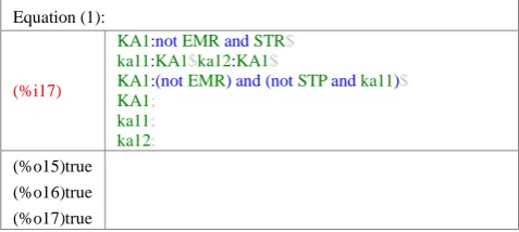
The state KA-1= {true} and how this was realized in the wxMaxima environment is shown in Table 3. It simulates Equation (1) that also depicts the status for contact ka11 and ka12 that belong to KA-1. Sections %o15, %o16, and %o17 present the outputs for KA1, ka11, and ka12, respectively. The results agree with Equation (1).
COMOUT CAM
SIMPLECV PYTHON
VS⋅ ⋅ ⋅ ⊃
− + − + → < ∆ → > ∆ = ∈ vh h vh h cam cam CAM CAM cam if if | f f vehicle no if vehicle incoming if | = ∈ −+ vh vh VH VH vh F
L v p J b M
M =∆ ∆ − Φ− ωΦ −
} true false, { if } false true, { if | = = = ∈ −+ RA RA m m M M m L L L L L F
L v p J b M
m+=∆ ∆ −
ϕ
+− ωϕ
+−F
L v p J b M
m−=∆ ∆ −
ϕ
−− ωϕ
−−Table 3. Equation (1) was written in wxMaxima standard scripts. The results are shown under %o15, %o16, and %o17 were the outcomes from %i17 of KA1, ka11, and ka12. This subroutine is a continuation from the scripts in Table 2
Equation (1):
(%i17)
KA1:not EMR and STR$
ka11:KA1$ka12:KA1$
KA1:(not EMR) and (not STP and ka11)$
KA1;
ka11;
ka12; (%o15)true (%o16)true (%o17)true
Equation (2), on the other hand, is dependent on Equation (3). So, the scripts shown in Table 4 has Equation (3) realized before Equation (2). When KA-3 was {true}, so would its contacts ka31. With this state, KA-2 would be {true} because ka12 and ka31 would have already been {true}.
When KA-2 was {true}, ka21 would close thus {true}, while NOT-ka22 would open thus {false}. The outcomes for KA-3 are shown in %o20, KA-2 in %o25. The results agree with Equation (2) and Equation (3). So, SS1 in Figure 4 should function well.
The state of the solenoids is dependent upon the state of the relay contacts belong to KA-2, defined in Equation (4). So the output of %o28 shown in Table 5 was {true} for SOL1 but {false} for SOL2 of %o29. The solenoids belong to a bistable DCV that either one of them should energize, but not both at the same instance, for the DCV to shift position.
[image:6.595.312.552.149.258.2]In this case, the dcv+ position should shift, as defined in Equation (8) and as resulted in %o30. When this occur, there exist a rapid air pressure change between the valve’s inlet and outlet ports that should produce inrush air velocity toward the port of the rotary actuator. It was the forward flow.
Table 4. The scripts were written to simulate Equation (3) and Equation (2)
Equation (3):
(%i21)
KA3:GintVout$ka31:KA3$
KA3;
ka31; (%o20)true
(%o21)true
Equation (2):
(%i27)
KA2:ka12 and ka31$ka21:KA2$ka22:KA2$
KA2;
ka21; not ka22; (%o25)true
(%o26)true (%o27)false
SS2 has a status format that differentiates between the forward flow and the reverse flow. So that, the forward flow form, STATE_SS2_INPUT {…, true, false, false, true}, whereas the reverse flow format, STATE_SS2_INPUT{…,
false, true, true, false}. It is readily defined in Equation (9), where FCV_A is forward-flow, while FCV_B is reverse-flow.
Table 5. The activation of the solenoids to open and close the valve’s ports
Equation (4):
(%i29) SOL1:ka21; SOL2:not ka22; (%o28) true
(%o29) false
Equation (8):
(%i31) dcv_plus:SOL1 and (not SOL2); dcv_minus:SOL2 and (not SOL1); (%o30) true
(%o31) false
For the given inputs FCV_A should become {true} and FCV_B {false}. Table 6 exhibits the outcomes proving Equation (9). With the %i33’s scripts, the results were %o32 {true), %o33 {false}, hence forward flow. Table 6. The strategy for flow controls that comes with a distinct format where the states of the respective devices are assumed in advance
Equation (9):
(%i33) FCV_A:fcv1_plus and fcv2_minus; FCV_B:fcv1_minus and fcv2_plus; (%o32) true
(%o33) false
[image:6.595.57.298.549.707.2]At this stage, it is imperative that the outcome of the systems downstream be determined. How the rotary actuator would react to the incoming air flow is expressed in equations (5), (6), and (7). We assumed that the RA would rotate CW with the assigned inputs. With forward flow was confirmed, ra+ should yield {true}, whereas ra- {false}. This is verified from %i35 in Table 7 where the state for ra+ {true} and ra- {false} in %o34 and %o35, respectively.
Table 7. In determining the pairwise condition for the direction of rotation. Equation (6) and Equation (7) express the desired direction of rotation with the assumed input states. Confirming the expression would verify the circuit operation if SS2 would achieve the prescribed operation
Equation (6) & (7):
(%i35)
ra_plus:SOV and (not EMV) and dcv_plus and
FCV_A;
ra_minus:SOV and (not EMV) and dcv_minus and
FCV_B; (%o34)true
[image:6.595.310.552.558.639.2](%o35)false
Table 8. The outcome provides a clear picture that the rotary actuator proceeds with CW rotation. Knowing that this result would be applied to the next equations, the whole system is now ready to operate in a complete manner
Equation (5):
(%i36) RA:{ra_plus,ra_minus}; (%o36) true, false
[image:6.595.315.550.687.730.2]the status of RA. When the pairwise result is {ra+, ra-} = {true, false}, it signifies that RA proceeds with a CW rotation. Similarly, if it is {false, true}, it continues with a CCW rotation. Otherwise, RA stalls. The CW rotation was verified from %o36 where the pairwise outcome was {true, false}.
It can be deduced that with a certain combination of inputs, a different outcome is expected at the system’s downstream. It is expressed in (19) assuming the necessary conditions are fulfilled.
(19) Now that the mechanical device, RA produces work, it is straightforward that the mechanics involve in the action is expressed for SS4. In SS3, however, before a signal is received from the COM port, the program needs to run a decision-making routine that computes every image frame data. Once incoming vehicles are detected, GINTVcomout should produce enough potential, hence {true}.
The RA would do work as long as there is sufficient pressure in its chamber. The amount of torque required to swing the MFO’s arm must overcome the constraints defined in Equation (13). The swing pace depends on the FCVs’ tuned orifice.
5. Conclusions
The system discussed in this paper was designed to the simplest architecture. It is the idea that it will be easy to operate and maintain. As for the logic expressions, they are meant to serve as the guides, mathematically expressed to describe how the subsystems function. Using the expressions, the system can be restructured with: an IoT architecture, a different type of actuation method, a higher speed machine vision, and more efficient computational routines. The MFO was tested in a controlled environment where the results showed that it has a potential for field implementation.
Acknowledgements
Students under the author supervision fabricated some of the parts and performed structural assembly of the MFO. The author would like to acknowledge the contributions of the following students: LY Lai, MFS Mohd Khairi, AF Ahmad Mawardi, MF Abu Bakar, MH Rosli, MNS Azman, N Abdul Rahman, MA Zulkefli, MES Mohd Hasni, and YV Yap. Also, the author would like to acknowledge the support of the Universiti Teknikal Malaysia Melaka, Short Term Research Program, under grant number S00872 PJP/2011/FKP (5C).
REFERENCES
[1] E. J. Cheon and N. M. Su, "Integrating roboticist values into a design framework for humanoid robots," in ACM/IEEE
International Conference on Human-Robot Interaction, 2016,
pp. 603-604.
[2] A. López, C. Peñaloza, and F. Cuéllar, "Influence of a humanoid robot in human decision-making when using direct & indirect requests," in ACM/IEEE International Conference
on Human-Robot Interaction, 2016, pp. 473-474.
[3] M. Cianchetti and C. Laschi, "Pleasant to the Touch: By Emulating Nature, Scientists Hope to Find Innovative New Uses for Soft Robotics in Health-Care Technology," IEEE
Pulse, vol. 7, pp. 34-37, 2016.
[4] G. Ma, J. Gao, Z. Yu, X. Chen, Q. Huang, and Y. Liu, "Development of a Socially Interactive System with Whole-Body Movements for BHR-4," International Journal
of Social Robotics, vol. 8, pp. 183-192, 2016.
[5] Y. Tadasse, L. Wu, and L. K. Saharan. (2016, March) Focus on Dynamic Systems and Control: Musculoskeletal System for Bio-Inspired Robotic Systems. Mechanical Engineering magazine. 11-16.
Available:https://www.researchgate.net/publication/3035657 85_MUSCULOSKELETAL_SYSTEM_OF_BIO-INSPIRE D_ROBOTIC_SYSTEMS
[6] A. S. Brown. (2016, April) Robots at Work: Where Do We Fit?
Mechanical Engineering magazine. 32-37. Available:
https://www.asme.org/engineering-topics/articles/technology -and-society/robots-at-work-where-do-we-fit
[7] N. Ramdan, A. Bani Hashim, S. R. Kamat, and S. A. Asmai, "Detecting Human Movement by Image Histogram to Monitor Body Discomfort," International Journal of Imaging
and Robotics™, vol. 16, pp. 45-57, 2016.
[8] N. Ramdan, A. Bani Hashim, S. R. Kamat, and S. A. Asmai, "Analysis of body dynamic posture to detect body discomfort by using a webcam and python image histogram," in Proceedings of Mechanical Engineering Research Day 2015:
MERD'15, 2015, pp. 141-142.
[9] N. S. Giges. (2014) A Social Robot for Every Household? Mechanical Engineering magazine.
Available:https://www.asme.org/engineering-topics/articles/r obotics/social-robot-for-every-household
[10] A. M. Sabelli and T. Kanda, "Robovie as a Mascot: A Qualitative Study for Long-Term Presence of Robots in a Shopping Mall," International Journal of Social Robotics, vol. 8, pp. 211-221, 2016.
[11] V. Vitaliev. (2016, June) Transport in the Smart City.
Engineering & Technology. 42-46.
[12] A. Y. Bani Hashim, "Big Data and Cloud Interoperability," in
Managing Big Data Integration in the Public Sector, A.
Aggarwal, Ed., ed: IGI Global, 2016, pp. 59-69.
[13] A. Bani Hashim, "Let the Machines Aware that they are Working Side by Side with Humans," Adv Robot Autom, vol. 4, p. e126, 2015.
[14] Online Available: http://www.asha.org/public/hearing/Noise/: Noise, American Speech Language Hearing Association, Online available from http://www.asha.org.
. 3 , 2 , 1
: SS SS SS ∴RA