Procedia Technology 8C (2013) 138 – 143
www.elsevier.com/locate/procedia
2212-0173 © 2013 The Authors. Published by Elsevier B.V.
Selection and peer-review under responsibility of the Faculty of Information Science and Technology, Universiti Kebangsaan Malaysia.
The 4th International Conference on Electrical Engineering and Informatics (ICEEI 2013)
Speed Tracking of Indirect Field Oriented Control Induction Motor
using Neural Network
Azuwien Aida Bohari
a,*, Wahyu Mulyo Utomo
a, Zainal Alam Haron
a, Nooradzianie
Muhd. Zin
a, Sy Yi Sim
a, Roslina Mat Ariff
aaFaculty of Electrical and Electronic Engineering, Universiti Tun Hussein Onn Malaysia, 86400 Parit Raja, Batu Pahat, Johor, Malaysia
Abstract
Development of a neural network (NN) based indirect field oriented control (IFOC) of induction motor (IM) drive is presented in this paper. The neural network indirect field oriented control (NNIFOC) is designed to generate signal of quadrature current, hence the motor speed will follow the reference speed value. The simulation model using Matlab/Simulink was developed to validate the effectiveness of the proposed controller. The simulation results show that the proposed NNIFOC schemes of IM drive is more effective and found to be a proper replacement of the proportional integral derivative (PID) controller.
© 2013 The Authors. Published by Elsevier B.V.
Selection and peer-review under responsibility of the Faculty of Information Science and Technology, Universiti Kebangsaan Malaysia.
Keywords: Induction Motor; Indirect Field Oriented Control; Neural Network Controller.
1.Introduction
A three phase IM is designed to operate from a three phase source of alternating voltage and it is a one of asynchronous AC motor. The advantages of the IM includes high reliability, relatively simple, has rugged structure,
* Corresponding author. Tel.: +60107604886; fax: +6074276876.
low cost, robustness and high efficiencies. These advantages make the IM advance in all aspects like speed change, speed reversal, starting and braking. The overall system performance depends on the IM dynamic operation. Due to the swift development in microprocessor and power electronic, the advanced control methods have IM possible for high performance applications. A lot of researcher has been attracted to the field of electric drives by IM control over time [1-14]. IM with variable speed ac drives and employed the field oriented control method expands in recent years to achieve better performances set by DC drives. In order to provide good steady-state performance in fast dynamic response, decoupling between the torque and flux is highly recommends. High dynamic performance in IM can be achieved by means of field-oriented control where it provides a suitable mathematical description of three phase IM.
The translation of coordinate from the fixed references stator frame to the frame of rotating synchronous is implied by the vector control [1]. In early 1970s, the decoupling technique makes the possibility of separated control for torque and flux in the complex dynamic for IM [2]. By applying the control techniques such as adaptive control [3] a good performance can be achieve with parameter sensitive property. A great attention has been made by NN due to its natural parallelism in the field of power electronic, thus allow and permit the high speed processing. The NN have capability for tolerance, to miss data, to fault, and to carry out in noise environment [4].
To identify and control nonlinear dynamic systems and nonlinear parameter estimation, the use of NN has been proposed [5][6]. An estimation of the stator flux and trained to map the nonlinear behavior of a rotor flux is performed on the proposed NN [7]. High performance control has been the objectives of [8], which presents robust neural controller and against variation of parameter. Without knowing the exact mathematical model of the system, the desired mapping between the input and outputs signals of the system can be learned by the NN. The NN are excellent estimators in non-linear system because it does not use the mathematical model of the system [9].
This paper will present a NN based IFOC of IM drive. The performance of three phase IM drive system with NN controlled applied in this paper. The theoretical principle, numerical simulation procedures and the results of these methods are discussed and compared with conventional PID controller.
2.Dynamic Modeling of IM
The IM model has been presented in a various reference frames. This makes it easier to adjust the model accordingly and to fix the reference frame to a particular motor quantity. Normally, a rotary type of induction is used with a rotating rotor and stationary stator. In order to derive the IM dynamic model of three phase coordinate into two phases direct and quadrature coordinate is required. The numeric model in stationary reference frame is given [10].
0 0
0 0
ds s s m ds
qs s s qs
m r m r r r r
dr dr
r m m r r r r
qr qr
V R L p L p i
V R L p Lp i
L p L R L p L
V i
L L p L R L p
V i
(1)
The reference frame of fixed d-q stator in IM model is described as follow,
( ) s s s d s
V R i
dt
0 ( )
r r r d r r r
V R i j
dt
s L is s Lm
r L im s L ir r
Whereas the mechanical equation is given as below:
( )
ds Vds R is ds dt
( )
qs Vqs R is qs dt
1
tan ( qs) s
ds
The electromagnetic torque of the machine can be presented as follow:
3
( )
4
e ds qs qs ds
p
T
i
i
3.IFOC System Description
The IFOC consists of controlling the stator currents represented by a vector. This control is based on projections which transform three phase time and speed dependent system into two co-ordinate time invariant system. This technique makes IM control scheme similar to a DC motor control scheme. In this IFOC technique, input and torque reference constant is required which aligned with the d-q axis by using this method. The control promise good quality of IM for both dynamic and steady-state operation.
4.Neural Network
Generally a NN controller was developing based on features of the human brains to handle complex problem and many task in one time. Basically the human brains system has ability to process the input information and the output data simultaneously and generate response instantaneously in handle multi job. By this reason many researcher believe that development of the NN control systems suitable for the nonlinear system. Development of the structure and learning algorithm of the NN is explained as follows [11].
4.1. Proposed NN speed controller
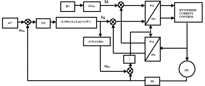
[image:3.539.96.453.505.656.2]This paper proposed a NN control method of IFOC based on hysteresis to reduce the overshoot and torque ripple.The NN control is added to the speed controller to produce the torque reference. The block diagram of the proposed NNIFOC of IM drive is shown in Fig. 1.
Fig. 1. The proposed NNIFOC diagram
HYSTERISIS CURRENT CONTROL
Pb
IM d-q
αbc 1/Lm
Ψ*
(1/Tr)(1/Ids) (2/3Pb)*(Lr/Lm)*(1/Ψ*)
ω* NN
d-q
αbc
Iq
ωm
ωsl
∫
4.2. Structure of NNIFOC
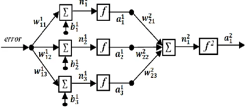
[image:4.539.146.397.130.242.2]Generally, input and output neuron number of the NN control system will be based on the input signal and output signal numbers. In order to develop the NNIFOC a multilayer perception with certain structure was proposed as shown in Fig. 2.
Fig. 2. Structure of NNIFOC
The controller consists of input layer, hidden layer and output layer. Based on number of the neuron in the layers, the NNIFOC is defined as a 1-3-1 network structure. The first neuron of the output layer is used as a torque reference signal (a21=mf). The connections weight parameter between jth and ith neuron at mth layer is given by wmij, while bias parameter of this layer at ith neuron is given by bmi. Transfer function of the network at ith neuron in mth layer is defined by:
1 1
1
m S
m m m m
i ij j i j
n w a b
The output function of neuron at mthlayer is given by:
( )
m m m
i i
a f n
Where f is activation function of the neuron. In this design the activation function of the output layer is unity and for the hidden layer is a tangent hyperbolic function given by:
2
2
( ) 1
1 mi m m
i n
f n
e
Updating of the connection weight and bias parameters are given by:
( ) ( 1) ( )
m m
ij ij m
ij
F k
w k w k
w
( ) ( 1) ( )
m m
i i m
i
F k
b k b k
b
5.Simulation Results
A simulation was constructed for the entire system in Fig 1 with the implementation of NN based IFOC scheme for the three-phase IM using Borland C++, and then embedded as S-function in Matlab/Simulink software. In this paper, the pattern of the reference speed that used to verify the effectiveness of the proposed controller is shown in Fig 3 the parameters for the motor are 240V, 50Hz, Poles=4, Rs=0.3Ω, Rr=0.25Ω, Ls=0.0415H, Lr=0.0412H, Lm=0.0403H, J=0.1kg-m2.
0 0.5 1 1.5 2 2.5 3 3.5 4 4.5 5
[image:5.539.162.382.159.299.2]0 20 40 60 80 100 120 140 Time (s) S p e e d ( ra d /s ) REFERENCE SPEED
Fig. 3. Pattern of the reference speed
The output response of the system based on the speed reference patern is shown in Fig. 4. and Fig. 5.
0 0.5 1 1.5 2 2.5 3
0 20 40 60 80 100 120 140 160 Time (s) S p e e d ( ra d /s ) PID CONTROLLER NN CONTROLLER
[image:5.539.67.477.343.479.2]0.5 0.505 0.51 0.515 0.52 0.525 0.53 0.535 0.54 0.545 0.55 20 25 30 35 40 45 50 Time (s) S p e e d ( ra d /s ) PID CONTROLLER NN CONTROLLER
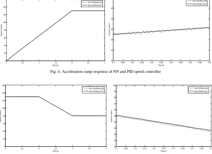
Fig. 4. Acceleration ramp response of NN and PID speed controller
2 2.5 3 3.5 4 4.5 5
0 20 40 60 80 100 120 140 160 Time (s) S p e e d ( ra d /s ) PID CONTROLLER NN CONTROLLER
3.7 3.705 3.71 3.715 3.72 3.725 3.73 3.735 3.74 3.745 3.75 90 91 92 93 94 95 96 97 98 99 100 Time (s) S p e e d ( ra d /s ) PID CONTROLLER NN CONTROLLER
[image:5.539.65.479.347.647.2] [image:5.539.66.481.510.645.2]Referring to the Fig 4, the acceleration ramp of the system by using both controllers in between time 0 to 2 seconds, shows that NN speed controller follow the shape of speed reference pattern and have a response improved from the conventional PID controller.
While, in Fig 5 between time 2 to 3 seconds, the speed continue at 130 rad/s. Then, NN speed controller follow the shape of deceleration ramp at the time of 3 to 5 seconds. The results for the both figure shows the great reduce in ripple of the transient respose and improved the performance at the same time rather than PID controller.
6. Conclusion
The NN based IFOC of IM drive system has been presented in this paper. The purpose of this paper is to investigate the performance of NN compared to the PID controller. The comparative results show that NN based IFOC schemes of IM drive is more effective and, hence, found to be a suitable replacement of the conventional PID controller. It is concluded that IFOC by using NN are useful and able to improve the performance. The result shows that the performance of the system is improved by reducing the ripple.
Acknowledgement
The author would like to gratitude University Tun Hussein Onn Malaysia for any valuable supports during conducting this research and in preparing this manuscript.
References
[1] Goyat, S. and Ahuja, R. K., “Speed Control of IM using Vector or Field Oriented Control”, Internationl Journal of Advances in Engineering and Technology. 2012.
[2] Blaschke, F., “The principle of field orientation as applied to the new transvector closed-loop control system for rotating-filed machines,” Siemens. 1972. Vol.34.p. 217-220.
[3] Von Zuben, F.J., Netto, M.L.A., Bim, E., Szajner, J., "Adaptive vector control of a three-phase IM using NNs," NNs, 1994. IEEE World Congress on Computational Intelligence., 1994 IEEE International Conference on , 1994. Vol 6.p.3750-3755
[4] Ba-Razzouk, A., Cheriti, A., Olivier, G.,1997."A NNs based field oriented control scheme for IMs," Industry Applications Conference, 1997. Thirty-Second IAS Annual Meeting, IAS '97., Conference Record of the 1997 IEEE , vol.2, no., pp.804-811.
[5] Wishart, M.T., Harley, R.G.,. "Identification and control of induction machines using artificial NNs," Industry Applications, IEEE Transactions on , 1995;31(3):612-619.
[6] Narendra, K.S., Parthasarathy, K., "Identification and control of dynamical systems using NNs," NNs, IEEE Transactions on , 1990. 1(1).p.4-27.
[7] Ba-Razzouk, A., Cheriti, A., Olivier, G., Sicard, P., "Field oriented control of IMs using NNs decouplers," Industrial Electronics, Control, and Instrumentation, 1995., Proceedings of the 1995 IEEE IECON 21st International Conference on , 1995.Vol. 2.p.1428-1433.
[8] Miloudi, A., Draou, A., 2001. "Neural controller design for speed control of an indirect field oriented induction machine drive," Industrial Electronics Society, IECON '01. The 27th Annual Conference of the IEEE. 2001. p.1225-1229 .
[9] Sivasubramaniam, A., “Application of neural network structure in voltage vector selection of direct torque control induction motor”
International Journal of Applied Engineering Research, 2009. 4(6),p.903.
[10] Kumar, Rajesh, Gupta, R.A., Bhangale, S.V., Gothwal, Himanshu; 2007. "Artificial NN based direct Torque Control of IM drives," Information and Communication Technology in Electrical Sciences (ICTES 2007), ICTES. IET-UK International Conference on , 2007. p.361-367.