DEVELOPMENT OF PC BASED FUZZY LOGIC CONTROLLER FOR DC MOTOR
WAN HASSAN BIN WAN HAMAT
A thesis submitted in
fulfillment of the requirement for the award of the Master of Electrical Engineering
Faculty of Electrical and Electronic Engineering Universiti Tun Hussein Onn Malaysia
v
ABSTRACT
ABSTRAK
vii
CONTENTS
TITLE i
DECLARATION ii
DEDICATION iii
ACKNOWLEDGEMENT iv
ABSTRACT v
CONTENTS vii
LIST OF TABLES ix
LIST OF FIGURES x
LIST OF SYMBOLS AND ABBREVIATIONS xii
CHAPTER 1 INTRODUCTION 1
1.1 Project background 1
1.2 Problem Statements 2
1.3 Project Objectives 2
1.4 Project Scopes 3
1.5 Thesis Overview 3
CHAPTER 2 LITERATURE REVIEW 3
2.1 Introduction 4
2.2 Fuzzy Logic Controller (FLC) 7
2.3 Feedback signal 8
2.4 System Identification 8
CHAPTER 3 METHODOLOGY 9
3.1 Introduction 10
3.2 Project Methodology 10
3.3 Project Arrangement Setup 11
3.4 Equipment 12
3.4.1 Personal Computer 13
3.4.3 Flexible Robot Manipulator (FRM) 15
3.4.4 Data Acquisition Card (DAQ Card) 15
3.5 Block Diagram 16
3.6 Feedback Signal 16
3.6.1 Strain Gauge 17
3.6.2 Encoder 18
3.7 System Identification 18
3.7.1 System Identification using Matlab 19 3.7.2 Step of Identification Using Matlab Toolbox 19
3.8 FLC Implementation 24
3.8.1 Basic operation of FLC 24
3.8.2 Process of FLC 25
3.8.3 FLC in LabVIEW 27
CHAPTER 4 RESULT AND ANALYSIS 30
4.1 Introduction 31
4.2 Modeling using System Identification 31
4.3 Simulation without FLC and with FLC 32
4.3.1 Without FLC (Uncontrolled) 32
4.3.2 With FLC (Controlled) 33
4.4 Result between Uncontrolled and Controlled 38 4.5 Rise Time (Tr), Settling Time (Ts) and Steady State Error
Analysis from Simulation using FLC 39
4.6 Experiment of FRM Control using FLC in LabVIEW. 40 4.6.1 FL Fuzzy Controller (Fuzzysetb.fs) 41
4.6.2 FL Fuzzy Controller (Fuzzyset.fs) 44
4.6.3 Experimental result Uncontrolled and Controlled 46
ix
CHAPTER 5 CONCLUSIONS AND FUTURE WORKS 51
5.1 Conclusion 52
5.2 Future works 53
LIST OF TABLE
Table 4.1 : Specification Range 34
Table 4.2 : Range of Membership Function for Input Variable 35 Table 4.3 : Range of Membership Function for Output Variable 36 Table 4.4 : Range of Membership Function for Input Variable Fuzzysetb 42 Table 4.5 : Range of Membership Function for Output Variable Fuzzysetb 42 Table 4.6 : Range of Membership Function for Input Variable fuzzyset 44 Table 4.7 : Range of Membership Function for Output Variable fuzzyset 45
Table 4.8 : Value of Tr, Ts And ess 50
Table 4.9 : Uncontrolled and Controlled CW 51
xi
LIST OF FIGURE
Figure 2.1 : DC motor modeling armature voltage control method 4
Figure 2.2 : DC motor function block diagram 6
Figure 2.3 : Block Diagram of DC Motor 7
Figure 3.1 : Project Methodology 11
Figure 3.2 : Connection between FRM, DAQ Interface Card and Laptop 12
Figure 3.3 : Equipment of Project Setup 12
Figure 3.4 : Labview Software Interface 14
Figure 3.5 : Flexible Robot Manipulator 15
Figure 3.6 : DAQ Card 15
Figure 3.7 : Block Diagram of System 16
Figure 3.8 : Strain Gauge 17
Figure 3.9 : Encoder 18
Figure 3.10 : System Identification Application Flow Chart 18
Figure 3.11 : Waveform of Encoder 19
Figure 3.12 : Waveform of Strain Gauge 20
Figure 3.13 : Matlab Command Window 20
Figure 3.14 : Main Identification Information Window 21 Figure 3.15 : Selecting Time Domain Data In Import Data Window 21
Figure 3.16 : Import Data Dialog Box 22
Figure 3.17 : Transfer Function for Estimate 22
Figure 3.18 : Model Output 23
Figure 3.19 : Transfer Function 23
Figure 3.20 : Basic Operation of FLC 24
Figure 3.21 : FLC Operations 25
Figure 3.22 : Process of FLC 25
Figure 3.23 : Fuzzy Logic Controller 27
Figure 3.24 : Select The Fuzzy System Designer 28 Figure 3.25 : Editor of Fuzzy System Designer 28
Figure 3.26 : Edit Variable Dialog Box 29
Figure 3.27 : Edit Variable for Setup The Range 29
Figure 3.29 : Test System or Fuzzy Controller 30 Figure 4.1 : Transfer Function From System Identification Toolbox 31
Figure 4.2 : Simulation Using Uncontrolled 32
Figure 4.3 : Angular Position Vs Time Using Uncontrolled 32
Figure 4.4 : Simulation Using FLC 33
Figure 4.5 : Angular Position Vs Time Using FLC 33
Figure 4.6 : FIS Editor 34
Figure 4.7 : Input Variable 35
Figure 4.8 : Output Variable 36
Figure 4.9 : Rule Base 37
Figure 4.10 : Rule Viewer 37
Figure 4.11 : Surface Viewer 38
Figure 4.12 : Angular Position Vs Time Using Uncontrolled And Flc 39
Figure 4.13 : Value of Tr, Ts And ℮ss 40
Figure 4.14 : GUI in LabVIEW 40
Figure 4.15 : Block diagram of FLC in LabVIEW 41 Figure 4.16 : Input Variable of Encoder Fuzzysetb 41 Figure 4.17 : Output Variable of Strain Gauge Fuzzysetb 42
Figure 4.18 : Rule Base Fuzzysetb 43
Figure 4.18 : Test System Fuzzysetb 43
Figure 4.19 : Input Variable of Encoder fuzzyset 43 Figure 4.20 : Output Variable of Strain Gauge fuzzyset 44
Figure 4.21 : Rule Base fuzzyset 45
Figure 4.22 : Test System fuzzyset 46
xiii
LIST OF SYMBOLS AND ABBREVIATIONS
Symbol
change in resistance caused by strain resistance of the unformed gauge
strain armature resistance armature inductance armature current field current input voltage
back electromotive force (EMF) motor torque
angular velocity of rotor
rotating inertial measurement of motor bearing damping coefficient
Tr Rise time
Ts Settling time ℮ss Steady state error FLC Fuzzy Logic Controller GUI Graphical User Interface DAQ Data Acquisition
FRM Flexible Robot Manipulator
PC Personel Computer
CW Clockwise
CCW Counter-Clockwise
GF Gauge Factor
DCM Discontinous Conduction Mode COA Centre Of Area
LIST OF APPENDICES
APPENDIX TITLE PAGE
A Data Sheet for Strain Gauge 57
B Data Sheet for Encoder 58
C Data Sheet for DAQ USB Card 59
CHAPTER 1
INTRODUCTION
1.1 Project background
The DC motors have been popular in the industry control for a long time, because it’s have many good characteristics. For example, high start torque characteristic, high response performance and easier to be linear control. The different control approach depends on the different performance of motors.
Because the peripheral control and devices are enough, there is the more extensive application in the industry control system. Therefore, the DC motor control is larger than other kinds of motors then are no matter in the theoretic study in the research and development application. The measurement and control can be achieved by PC-based. However, the technique of Instrument design also moves forward the times of “virtual instrument”, not only the designing time is shorten, but also the designing space is more elastic extension. This project presents to guide the motor speed control field with the various advanced computer technology and the development platform of software/hardware. Let the dynamic state response of motor have a better efficiency.
1.2 Problem Statements
Basically in industrial applications is used DC motors, because the speed and torque relationship can be varied and regeneration applications in either direction of rotation. DC motor is use in Robotic Machine, Lift Motor, Crane Motor and etc. So the motor must be operates in perfect condition to avoid the machine cannot run smoothly. DC motor also needs additional controller to control the performance rotation the motor on starts conditions. Mostly in industries used DC Motor without controller in order to save the cost. The effect of this case, DC motor is possibly damage because at certain times run with on and off condition. The DC motor also cannot run smooth and precisely without controller.
In this project is propose to design FLC to control the speed of DC motor using the Labview software program and display the speed of the motor in real-time in order to obtain the system response of FLC. The real-time monitor of application on the motor not only can substitute the traditional instrument but also can be as the monitor basis of the machine operating normally or not. This programming system is based on a structure of the PC, and combines the DC motor supervision needed instrument which then replaces other hardware equipment with the cheaper and more efficient method to facilitate operators with the graphical interface of an easy and kind operation.
1.3 Project Objectives
The objectives of this project are;
i) To design the modeling system using FLC to control the speed of DC motor using Matlab.
ii) To develop the FLC in Labview to control DC motor using FRM hardware by PC Based method.
3
1.4 Project Scopes
The scopes of this project is to simulate the FLC response of DC motor with MATLAB Simulink software. For the Hardware, FRM hardware is used to show the analysis of DC motor response.
1.5 Thesis Overview
This project report is organized as follows;
i) Chapter 1 briefs the overall background of the study. A quick glimpse of study touched in first sub-topic. The heart of study such as problem statement, project objective, and project scope and project report layout is present well through this chapter.
ii) Chapter 2 covers the literature review of previous case study based on FLC controller background and development. Besides, general information about hardware interface and DC motor modeling and theoretical revision on FLC also described in this chapter.
iii) Chapter 3 presents the methodology used to design Fuzzy Logic controller and PC based hardware model system. All the components that have been used in designing FLC are described well in this chapter.
iv) Chapter 4 reports and discuss on the results obtained based on the problem statements as mentioned in the first chapter. The simulation results from output controller will be analyzed with helps from set of figures and tables. v) Chapter 5 will go through about the conclusion and recommendation for
LITERATURE REVIEW
2.1 Introduction
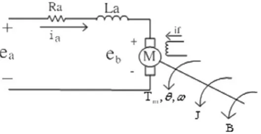
[image:15.595.191.456.526.662.2]This DC motor system is a separately excited DC motor, which is often used to the velocity tuning and the position adjustment. This project focuses on the study of DC motor linear speed control, therefore, the separately excited DC motor is adopted. Make use of the armature voltage control method to control the DC motor velocity, the armature voltage is controls distinguishing feature of method as the flux fixed, and current fixed as well. The control equivalent circuit of the DC motor by the armature voltage control method is shown in Figure 1.
Fig. 2.1: DC motor modeling armature voltage control method
where;
5
: the armature inductance : the armature current the field current : the input voltage
the back electromotive force (EMF) the motor torque
an angular velocity of rotor
rotating inertial measurement of motor bearing a damping coefficient
Because the back EMF is proportional to speed ω directly, then
Making use of the KCL voltage law can get
From Newton law, the motor torque can obtain
Take 2.1 – 2.3 into Laplace transform, respectively, the equations can be formulated as follows:
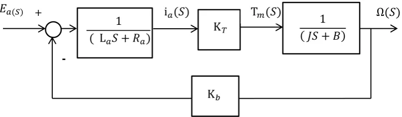
Fig. 2.2 describes the DC motor armature control system function block diagram from equations (1) to (6).
𝑒
𝑏𝑡 = K
𝑏𝑑𝜃 𝑡
𝑑𝑡
= K
𝑏𝜔 𝑡
(2.1)𝑇
𝑚𝑡 = J
𝑑
2𝜃 𝑡
𝑑𝑡
2+ 𝐵
𝑑𝜃 𝑡
𝑑𝑡
= 𝐾
𝑡i
𝑎 (2.3)𝐸𝑎 𝑆 = R𝑎 + L𝑎 𝑆 i𝑎 𝑆 + 𝐸𝑎 𝑆 (2.4)
𝐸𝑏 𝑆 = 𝐾𝑏 Ω 𝑆 (2.5)
Fig. 2.2: DC motor armature voltage control system function block diagram.
The transfer function of DC motor speed with respect to the input voltage can be written as follows;
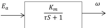
From equation (2.7) the armature inductance is very small in practices, hence, the transfer function of DC motor speed to the input voltage can be simplified as follows;
Where,
is a motor gain,
is a motor time constant.
𝐺 𝑆 = Ω 𝑆
𝐸𝑎 𝑆 = J
𝐾𝑇
L𝑎𝑆 + 𝑅𝑎 𝐽𝑆 + 𝐵 + 𝐾𝑏 𝐾𝑇 (2.7)
Ω 𝑆
𝐸𝑎 𝑆 =
𝐾𝑚
𝜏𝑆 + 1 (2.8)
𝐾𝑚 =
𝐾𝑇
𝑅𝑎𝐵 + 𝐾𝑏 𝐾𝑇 (2.9)
𝜏 = 𝑅𝑎 𝐽
𝑅𝑎𝐵 + 𝐾𝑏 𝐾𝑇 (2.10)
+
-
1
L +
i 1
+
K K
7
[image:18.595.240.429.123.172.2]From equation (2.8), the transfer function can be drawn the DC motor system block diagram which is shown in Figure 2.3.
Fig. 2.3: Block diagram of DC motor
2.2 Fuzzy Logic Controller (FLC)
The previous researcher develops the FLC for trajectory tracking of tip angular position and vibration control of flexible joint manipulator. Initially a PD-type FLC is developed for trajectory tracking of tip angular position. This is extended to incorporate non-collected FLC for vibration control of the manipulator. The performances are examined in term of input tracking capability, level of reduction and time response specification [1].
FLC is the better control for control the vibration of flexible robot. Based on research paper in [5] mention for improvement process, and since then many papers have addressed robot control in combination with FLC. Furthermore, by using FLC application it can help to control active vibration of a very flexible link manipulator [6]. Then, other researchers mention using FLC for active vibrations control [7].
The fuzzy control method is quite useful in terms of reliability and robustness. The FLC has been increased interest in applying the concepts of fuzzy set theory to flexible structural control. Fuzzy controllers afford a simple and robust framework to specify nonlinear control laws that accommodate uncertainly and imprecision [8].
FLC have some advantage compared to other classical controller such as simplicity of control, low cost and the possibility to design without knowing the exact mathematical model of the process. Fuzzy logic incorporates an alternative way of thinking which allows modeling complex systems using higher level of abstraction originating from the knowledge and experience. Fuzzy logic can be describes simply as “computing words rather than numbers” or “control with sentence rather than equations” [9].
FLC have been successfully employed to universal approximate mathematical model of dynamic system in the recent years. The FLC offer an efficient alternative to classical methods of modelling and control of nonlinear system. Although a number of fuzzy position control system for robot manipulator are available, only a few have consideration of torque or current limits [10].
2.3 Feedback signal
The feedback sensors in this project are encoder and strain gauge to control the vibration on system. The researcher on [11] mention previous researcher (Luo) used a strain gauge sensor to measure the flexible robot. According [12] mention experiment on flexible robot manipulator purpose controlling the end tip position of the flexible link, the passive velocity feedback and strain feedback approaches to control the vibration of flexible link robot. The purpose of using strain feedback is trying to damp out the flexible link vibration. The researcher mention base on nonlinear dynamical model, the nonlinear control schemes such as, those using computed torque method, inverse dynamic, feedback linearization and sliding mode control have been proposed for control of flexible robot arm. Based on the development models by researcher, an output feedback nonlinear control strategy is proposed with motion duration of 0.5 second. It means that the tracking capability of the flexible robot arm follow fast motion duration improvement.
The vibration control strategy separated into feed forward and feedback part. The idea of feed forward approaches is to shape the original reference signal in a way that minimizes the excitation of Eigen frequencies in the flexible structure. Feedback strategies in contrast include direct measurements or estimate of vibration states and outputs to control the vibration motion. In this way robustness against system parameter uncertainties, modeling errors and disturbance is achieved [13].
2.4 System Identification
9
modeling of system using system identification. The researchers in [14] have built the modeling by using system identification base on measured data. The parameters need to adjust within a given model until the output accordance with the measure output.
In [15], they introduce the MATLAB as a software package included of high performance and interactive numerical computation, data analysis, and graphics. The MATLAB toolboxes make this software most powerful in the specific field include one of them is System Identification Toolbox. The command of the toolbox is divided into five layers include of basics tools, model structure selection, more methods to examine models and multi-input system, recursive identification, and state-space modelling.
The researcher in [16] provides a graphical user interface (GUI) for System Identification Toolbox. The GUI has been successfully in modeling and developing the mathematical model of the system. The researcher was introduced the system identification problem, the graphical user interface of the system identification, common terms used in system identification, basic information about the dynamic system, the basic steps of system identification and a start-up identification procedure. The close look from the model’s output is used to get a good test compare to the measured one of a data set that was not used for the fit of validation data.
METHODOLOGY
3.1 Introduction
In this section, all the procedures, steps and flow chart that have been used in the simulation and experiment to archive the project objective is presented. The method of DC Motor control by using FLC has been discussed in this chapter. For the DC Motor model, FRM is used to show the application of DC Motor movement.
3.2 Project Methodology
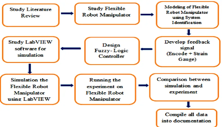
Firstly, literature review have been done by referring to previous chapter decide the method that can be used for project include the knowledge about modelling of DC Motor and FLC. Next, the mechanical structure of FRM has been studied to know the function for each component in FRM. After that, the modeling by using System Identification needs to build. From the System Identification by using either LabVIEW or MATLAB need to construct the transfer function for the FRM model. Then, the encoder and strain gauge are used in this system for the purpose of feedback signal. The FLC have been study to use as a controller on FRM.
11
[image:22.595.122.506.129.349.2]data need to compile into the documentation of the project. Project methodology for this project was shown in Figure 3.1.
Figure 3.1: Project methodology
3.3 Project Arrangement Setup
Figure 3.2: Connection between FRM, DAQ Interface Card and Laptop.
In order to configure the personal computer to work with specific interface card a driver in LabView software needed to be set compatible driver with the same interface card model number. Input and output of interface card are fixed by manufacturer and can be referred to data sheet provided for troubleshooting purposes. In this arrangement, FRM used as experimental equipment where educational boards, sensors and motors are located inside.
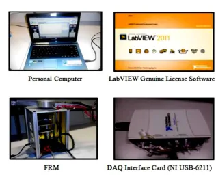
3.4 Equipment
[image:23.595.155.472.483.739.2]13
Figure 3.3 shows the equipment that used for project arrangement include of Personal Computer, LabVIEW Genuine Licence Software, FRM and DAQ Interface Card (NI USB 6211).
3.4.1 Personal Computer
The Personal Computer is used to control the whole system that using in this project. It also needs to process the data between hardware and software. From Personal Computer, all the data and result were shown to observe after running the simulation and experiment.
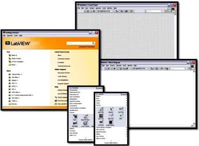
3.4.2 LabVIEW Software
The LabVIEW (Laboratory Virtual Instrumentation Engineering Workbench) is a system design platform and highly productive development environment for a visual programming language from National Instruments. Furthermore, LabVIEW is a graphical programming language and unprecedented hardware integration to rapidly design and deploy measurement and control systems. It has been widely adopted throughout industry, academia and research labs as the standard for data acquisition and instrument control software. LabVIEW is a powerful and flexible instrumentation and analysis software system that is multiplatform.
Its graphical programming is:
i. Easy to use
vi. Application Builder to create stand-alone executable
The most advantage when using LabVIEW over other development an environment is the extensive support for accessing instrumentation hardware.
[image:25.595.119.519.212.505.2]Figure 3.4 shows the LabVIEW Software Interface that used to develop the Fuzzy Logic Controller for controlling the vibration of FRM.
15
[image:26.595.224.418.112.250.2]3.4.3 Flexible Robot Manipulator (FRM)
Figure 3.5: Flexible Robot Manipulator
Figure 3.5 shows the several items on FRM include of Encoder, Motor Strain Gauge as a sensor and the important part of robot to use for experiment is the link of FRM. The FRM system consists of:
i. DC motor ii. Strain Gauge
iii. Motor position sensor (encoder) iv. DC Motor
v. Power supply 24V vi. Power Supply 9V vii. Stopper Switch (safety)
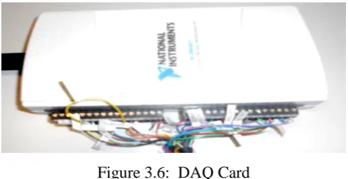
[image:26.595.193.446.617.747.2]3.4.4 Data Acquisition Card (DAQ Card)
Data acquisition is the process from the sampling of the real world to generate and converting the data into digital numeric that can manipulate by computer. Data acquisition typically involves acquisitions of signals and waveform and processing the signals to obtain desired information.
Figure 3.6 shows the DAQ Card type of NI USB-6211 that use for this project to process the data acquisition include as interfaces between FRM and laptop.
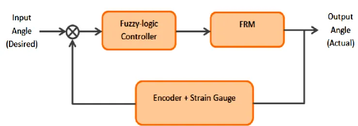
[image:27.595.130.500.275.405.2]3.5 Block Diagram
Figure 3.7: Block Diagram of system
Figure 3.7 shows block diagram of implement the FLC as a controller also encoder and strain gauge as a feedback signal in FRM system. The input for the system which is called desired angle while output for the system is called actual output after goes through certain process. The main component in this project refers to Fuzzy Logic Controller (FLC) block where it is used to control all operation in this system. Basically the FLC will consider feedback input signal such as encoder and strain gauge to the controller. All block diagrams shown involved all equipment mention earlier.
3.6 Feedback Signal
17
actual value detected by a sensor which is strain gauge and encoder as a process is taking place.
3.6.1 Strain Gauge
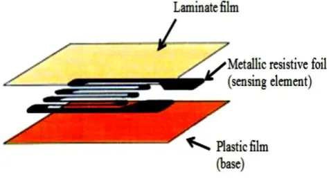
[image:28.595.202.440.289.418.2]A strain gauge is a device that used change in electrical resistance to measure the strain of an object. The Strain Gauge has a structure such that a grip-shaped sensing element of thin metallic resistive foil that put on a base of thin plastic film and is laminated with a thin film. In Figure 3.8 shows the structure of strain gauge.
Figure 3.8: Strain Gauge
A fundamental parameter for the strain gauge is its sensitivity to strain that expressed quantitatively as the gauge factor (GF). The GF defined as the ratio of fractional change in electrical change in electrical resistance to the fractional change in length strain:
Where
= the change in resistance caused by strain
= the resistance of the unformed gauge
= the strain
3.6.2 Encoder
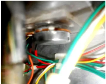
[image:29.595.101.537.114.671.2]Encoder is sensors that generate the digital signals in response to movement the link of FRM. Both shaft encoders, which is response to rotation, and linear encoder which is response to motions in a line are variable. Encoder act as feedback transducers for motor- speed control and as sensor for measuring the position between -90˚ to 90˚ of FRM. Figure 3.9 shows the encoder that using for feedback signal on FRM.
Figure 3.9: Encoder
[image:29.595.230.408.235.376.2]3.7 System Identification
Figure 3.10: System Identification application flow chart
[image:29.595.117.525.493.635.2]19
stimulus and response data samples. System Identification is fundamental for communication and control engineering, and plays as roles in many other areas.
3.7.1 System Identification using Matlab
The MATLAB provide System Identification Toolkit an interactive tool for identifying the Transfer Function of the system. This toolkit encompasses the entire identification process from raw data analysis to validation of identified models. To investigate the System Identification of the model in the MATLAB software, the input and output data was from the FRM model.
3.7.2 Step of System Identification Using Matlab Toolbox
This part describes the procedures to obtain the Transfer Function model from the input and output data using MATLAB System Identification Toolbox. The steps taken are as follows;
[image:30.595.156.520.524.698.2]i. The data of encoder and strain gauge is taken from the movement of link on FRM. Figure 3.11 shows the value of encoder as an input of variable in LabVIEW.
Figure 3.12: Waveform of Strain Gauge
[image:31.595.163.487.425.602.2]ii. The command ‘ident’ was type on MATLAB command windows as shown in Figure 3.13. The main identification windows are opened as shown in Figure 3.14.
21
Figure 3.14: Main identification information window
iii. At the import data window, the Time domain data was selected. This is shown in Figure 3.15. The Import data dialog box is open as shown in Figure 3.16.
[image:32.595.153.482.359.583.2]Figure 3.16: Import data dialog box
iv. At the Workspace Variable window as shown in Figure 3.16, the Input was fill-in with ‘Encoder’ and the Output with ‘Strain Gauge’. Next, Import button was clicked to import the information data into a main indent information window.
v. Next, in Figure 3.17 shows the Transfer Function was clicked for estimate the input and output. Then in Figure 3.18 and Figure 3.19 shows the estimation result includes value of encoder and strain gauge.
[image:33.595.187.459.561.732.2]23
Figure 3.18: Model output
[image:34.595.186.449.296.518.2]3.8 FLC Implementation
[image:35.595.173.467.162.266.2]3.8.1 Basic operation of FLC
Figure 3.20: Basic Operation of FLC
Figure 3.20 shows the basic operation of FLC to control the vibration of FRM. There are many types of controller that can be implemented to control the vibration of FRM. FLC effective to control a discrete system that needs high level of sensitivity in order to control feedback signal. FLC refer to a system that reads signals from feedback system (encoder and strain gauge) and control the output pattern (motor movement) by considering the feedback signal as error.
54
REFERENCE
[1] M. T. Mete Kalyonco, Hierarchical Adaptive Network Based Fuzzy Logic Controller, 13th Internasional power Electronics and Motion Control Conference (EPE-PEMC), Konya, Turkey, 2008.
[2] W. A. Kwong, K. M. Passino, S. Yurkorich and Vivek G. Moudgal, Fuzzy Learning Control For A Flexible-Link Robot, IEEE Transactions On Fuzzy System, Vol3, USA, May, 1995.
[3] M. A. Ahmad, A. N. K. Nasir and N. Hambali, Techniques Of Vibration Feedbck Control Of A Flexible Robot Manipulator, Proceeding of the 6th International Symposium On Mechatronics And Its Application (ISMA09), UAE, 2009.
[4] M. A. Ahmad, R. Ismail, M. S. Ramli, Control Strategy For Active Vibration Suppression Of Flexible Robot Manipulator, Internasional Conference On Information And Automation, Harbin, China, 2010.
[5] W. A. Kwong, K. M. Passino, S. Yurkorich and Vivek G. Moudgal, Fuzzy Learning Control For A Flexible-Link Robot, Proceding of the America Control Conference, Baltimore, Maryland, 1994.
[6] G. Vukovic and J. X. Lee, Fuzzy Logic Control Of Flexible Link Manipulator Demonstrations Controller design And Experiment, IEEE, Canada, 1998.
[8] J. Lin and F. L. Lewis, Fuzzy Controller For Flexible-link Robot Arm By Reduce-Order Techniques, IEEE Proc.-Control Theory A&, Vol. 147, No. 3, Texas, USA, 2002.
[9] E. Natsheh and K. A. Buragga, Comparison Between Conventional And Fuzzy Logic PID Controllers For Controlling DC Motors, IJCSI International Journal of Computer Science Issues, Vol. 7, Issue 5, Saudi Arabia, September 2010.
[10] J. Velagic and A. Aksamovic, Fuzzy Logic System For Position Control And Current Stabilization Of A Robot Manipulator, IEEE, Serbia & Montenegro, Belgrade, 2005.
[11] M. H. Korayeem, A. M. Shafel and F. Absalam, Estimate A Flexible Link's Shape By The Use Of Starain Gauge Sensor, Hindawi Publishing
Corporation ISRN Robotic, Vol 2013, Tehran, Iran, 2013.
[12] H. Bolandi and S. M. Esmaeilzadeh, Adaptive Nonlinear Sensor Output Feedback Control Of A Flexible Robot Arm, International Conference on Computer and Electrical Engineering, Iran, 2008.
[13] J. Malzahn, M. Ruderman, A. S. Phung, F. Hoffmann and T. Bertam, Input Shaping And Strain Gauge Feedback Vibration Control Of An Elastic Robotic Arm, Conference on Control and Fault Tolerant System, Nice, France, 2010.
[14] L. Ljang, System Identification, in The Control Handbook, Swedan, CRC Press, Inc, 1996, pp. 1033-1053.
56
[16] L. Ljung, "System Identification," in The Control Handbook, Sweden, CRC Press, Inc., 1996, pp. 1033-1053.
[17] Srinivasan, M. B., A. Shirkhodaie, and M. Malkani, LabVIEW program design for on-line data acquision and dpredictive maintenance. Proceedings of the Thirtieth IEEE Souteastern Symposinm on System Theory, 1998, pp.520-524.
[18] Baek, S. M. and T. Y. Kuc., "An adaptive PID learning control of DC motor",
IEEE International, Volume.3, 1997, pp.2877-2882.
[19] P. I-H. Lin and M. Rashid "A PC-Based Measurement and Control System for DC Motors", Conference Record of 1990 IEEE Industry applications society annual meeting, pp.1829 -1834.