International Journal of Emerging Technology and Advanced Engineering
Website: www.ijetae.com (ISSN 2250-2459, Volume 1, Issue 1, November 2011)35
A Microprocessor Based Clutter Canceller for Life Locator
System
G. N. Zade
1and S. S. Thakare
21
Goverment college of Engineering, Department of Electronics and Tele-Communication, Amravati, M.S., (India) [email protected]
2
Goverment college of Engineering, Department of Electronics and Tele-Communication, Amravati, M.S., (India) Designation: Asst. Professor ,GCOEA, M.S., (India)
Abstract:A Clutter canceller is microprocessor based system to cancel the unwanted clutter signal received from rubble or from the building debris. It mainly consists of programmable phase shifter and programmable attenuator. This subsystem is equipped with life locator system to avoid the backscattered microwave signal from immobile objects. A series of experiment have benn conducted to see the capability of clutter canceller system.
Keywords: Clutter signals, Doppler shift, dual antenna system, Life under rubble, programmable phase shifter, and programmable attenuator.
I. INTRODUCTION
Recently, a microwave life locator system has been design to locate trapped victim under earthquake rubble or building debris. This life detector can work on L- band or
X-band frequency [1]. The basic principle of life detection
system as shown in fig. 2 is to illuminate the human subject with a microwave frequency and these frequency sense the
body vibration occur due to breathing and heart beats [2]. This
body vibration can be detected by phase detection as they
cause phase modulation according to Doppler shift [3]. But
with this modulated signal the system also receives the signal (known as clutter signal) reflected from the motionless objects such as building debris. It is very necessary to avoid those clutter signals. Here, the clutter canceller plays role. Canceller works as subsystem of life locator system.
Fig. 1 Rescue operation by Life Locator System [4]
International Journal of Emerging Technology and Advanced Engineering
Website: www.ijetae.com (ISSN 2250-2459, Volume 1, Issue 1, November 2011)36
A series of experiment has been conducted to observe the performance of life locator system for various frequency bands. It was found that lower frequency band can penetrate more deeper into the rubble than higher frequency band. But the higher frequency can penetrate through metal sheet also whereas lower frequency can’t. So, if someone wants to rescue more number of victims it is suggested to deal with lower frequency band such as L-band or S-band
[image:2.612.110.256.152.289.2]Fig 2. Principle of operation of life locator system
Fig. 3 Block Diagram of Life Locater System [6]
II.MATERIALS AND BLOCK DIAGRAM
Fig.3 shows the block diagram of Life Locator system is as shown in fig. 3. The SAW oscillator can be used to generate L-band or X- Band frequency. The microwave frequency is fed to directional coupler whose one output is given to power
amplifier and other will works as reference signal for clutter canceller . The received signal consists of both modulated signal as well as clutter signal. This received signal coupled with signal generated by clutter canceller and the signal with opposite magnitude and same phase i.e. clutter signal get
[image:2.612.54.567.315.545.2]International Journal of Emerging Technology and Advanced Engineering
Website: www.ijetae.com (ISSN 2250-2459, Volume 1, Issue 1, November 2011)37
In a life locator system the clutter signal obtained from the surrounding motionless object must be avoided in order to get only phase modulated wave. The clutter canceller system consists of phase attenuator, phase shifter which are programmed by microprocessor, translator circuit, detector and A/D convertor is inbuilt in the microprocessor unit. Fig. 4 shows the basic block diagram of canceller. Since, the microprocessor requires digital data for processing, it is need to use A/D converter. The 8 bit successive approximation convertor and works with 5V power supply. The detector feds the DC level of received signal so that it can converted to digital data.
III. MICROPROCESSOR BASED UNIT FOE CLUTTER CANCELLER
The clutter signal is passed through a detector as shown in fig. 4(in the last page of this paper) which outputs a
DC voltage of few tens mV. Then it is amplified by an operational amplifier and fed to A/D converter who’s outputted to the Port A of microprocessor. The output port C and port B are connected to the phase attenuator and phase shifter respectively. The controller uses different combination of attenuation and phase shifting to achieve optimum level. It starts with the initial clutter signal as a reference. The microcontroller sets 1 dB as a minimum attenuation in the
attenuator and tries all phase settings from 00 to 3600 in the
phase shifter and repeats the procedure until it gets the minimum DC output of detector and sets attenuator and phase shifter control switches accordingly. Maximum cancellation depends on the resolution of attenuator and phase shifter and properties of rubble like constituents of the barrier, shape, size, its orientation with respect to the direction of incident radio wave etc.
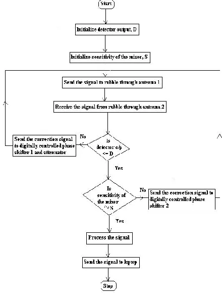
A. Canceller Operation:
[image:3.612.339.559.345.644.2]The operation of canceller can studied from its flow chart as shown in fig. 5.Initially detector level is adjusted to the desired DC level of the corresponding received signal. Also with this sensitivity of the mixer placed at the output side is set. Here dual antenna system is being used with a programmable switch. At position 1, it works as transmitting and at position 2, it will works as receiving antenna. After receiving the signal by antenna 2, the signal is fed to detector. Here the DC level of received signal is compare with D. If it is not less than or equal to D, it send back for transmission and if it is less than or equal to D then it compare with S. If received signal is approximately equal to S then the signal is process by the signal processing unit for phase detection.
International Journal of Emerging Technology and Advanced Engineering
Website: www.ijetae.com (ISSN 2250-2459, Volume 1, Issue 1, November 2011)38
VI. RESULT
A several experiments are performed with the life detection system. Various layers of bricks were used to simulate the thickness W of rubble or barrier and the distance between the victim and the barrier of rubble D was a variable parameter for the experiment. In the graphs, the heartbeat signal (when the human subject holding his breath), the breathing signal, and the background noise were include. Firstly, the heartbeat and breathing signals were detected for each position. When the thickness of this wall increases to eight layers (about 90 cm), the performance of the L band life-detecting system became marginal. For the distance D =16 m, the system was marginal. Fig.6 to Fig12 is the Fast Fourier Transform (FFT) of the time-domain signal, which shows the frequency components of the time-domain signal. Fig.7 to Fig.9 show the same result performed on the same distance D for the different thickness as shown respectively. The frequency domain FFT results show the peaks of heartbeat signal (0.8 Hz to 2.5Hz) and breathing signal (0.2 Hz to 0.5 Hz). Other small peaks are probably due to noises
or the second harmonic of the breathing signal[10]. When all
these result were compared it is found that the amplitude of the breathing signal is becoming smaller with the increase of the wall’s thickness. The heartbeat signal peak also decreases with the increase of the wall’s thickness. Fig.10 to Fig.12 show the FFT results behind the same wall.
The distance (D) is 4m, 8m and 12m accordingly. It can be concluded from the result, thickness affects breathing signal whereas distance D affects heartbeats signals. The L band system performs better enough for remotely buried victims signals.
Our experiments prove that a buried victim can be efficiently detected using lower band frequency.
Fig.6 Frequency spectrum of background noise [11]
International Journal of Emerging Technology and Advanced Engineering
Website: www.ijetae.com (ISSN 2250-2459, Volume 1, Issue 1, November 2011)39
Fig. 8 Frequency spectrum of breathing and heartbeat, D=1m, W=48cm [11]
Fig.9 Frequency spectrum of breathing and heartbeat, D=1m, W=60cm[11]
Fig.10 Frequency spectrum of breathing and heartbeat, D=4m, W=24cm[11]
Fig.11 Frequency spectrum of breathing and heartbeat, D=8m, W=24cm
International Journal of Emerging Technology and Advanced Engineering
Website: www.ijetae.com (ISSN 2250-2459, Volume 1, Issue 1, November 2011)40
Fig.12 Frequency spectrum of breathing and heartbeat, D=12m, W=24cm[11]V. CONCLUSION
We have developed a microprocessor based life locator system which can locate the trapped human being buried under earthquake rubble or into the building debris. The microprocessor based clutter cancellation system is a heart of life locator. It is responsible to produce most efficient output regarding detection of trapped victims. The X- band system can penetrate 5layers of bricks and it can penetrate metal also. Besides this L-band system performs well as it can penetrate 10layers of bricks. This system has applicable in CW radar system where the microprocessor based clutter canceller has essential function to expand range of operation.
References:
[1] Chen,K. M.,D. Misra,H. Wang,H. L. Chueng,et al.,“An Xband M/W life-detection system,” IEEE Trans. Biomedical Eng., Vol. BME-33,697–701,July 1986.
[2] M. Donelli,”A rescue radar system for the detection of victims trapped under rubble based on the independent component analysis algorithm.” Progress In Electromagnetics Research M, Vol. 19, 173-181, 2011. [3]. A. Izadi, Z. Ghatan, B. Vosoughi Vahdat and F. Farzaneh, “Design and
Simulation of Life Detection System Based on detection of the Hear Beat Using Doppler Frequency,” IEEE International Symposium on Signal Processing and Information Technology, 2006.
[4] Chen KM, Huang Y, Zhang JP, Norman A, “RF life-detection systems for searching human being”, IEEE TRANSACTIONS ON BIOMEDICAL ENGINEERING, Pages 105-114, JAN 1991
[5] Chen KM, Huang Y, Zhang JP, Norman A, “RF life-detection systems for searching human being”, IEEE TRANSACTIONS ON BIOMEDICAL ENGINEERING, Pages 105-114, JAN 1991. [6] . W. S. Haddad, “The Rubble Rescue Radar (RRR): A Low Power
Hand-Held Microwave Device for the Detection of Trapped Human Personnel”, Work performed under the auspices of the US .Department
of Energy by the Lawrence Livermore National Laboratory under Contract W-7405-Eng43. APRIL 1997.
[7] M. Bimpas, N. Paraskevopoulos, K. Nikellis, D. Economou and N. Uzunoglu, “Development of a three band radar system for detecting trapped alive humans under building ruins” Progress in electromagnetic research, pier 49, 161–188, 2004
[8] M. D'Urso, “A SIMPLE STRATEGY FOR LIFE SIGNS DETECTION VIA AN X-BAND EXPERIMENTAL SET-UP” Centro Ricerche Giugliano, SELEX Sistemi Integrati SpA Via Circumvallazione Esterna di Napoli, zona ASI, Giugliano, I-80014, ItalyProgress In Electromagnetics Research C, Vol. 9, 119{129, 2009
[9] Wu, C. W. and Z. Y. Huang ,”Using the Phase Change of a Reflected Microwave to Detect a Human Subject Behind a Barrier” IEEE Transaction Biomedical Engg, Vol. 55. No. 1, 267-2272, 2008. [10] Yanming Xiao; Changzhi Li; Jenshan Lin; “Accuracy of A
Low-Power Ka-Band Non-Contact Heartbeat Detector Measured from Four Sides of A Human Body ” Dept. of Electr. & Comput. Eng., Florida Univ., Gainesville, FL, : Microwave Symposium Digest, 2006. IEEE MTT-S International June 2006.
![Fig. 3 Block Diagram of Life Locater System [6]](https://thumb-us.123doks.com/thumbv2/123dok_us/8747729.891193/2.612.54.567.315.545/fig-block-diagram-life-locater.webp)