2017 3rd International Conference on Artificial Intelligence and Industrial Engineering (AIIE 2017) ISBN: 978-1-60595-520-9
Study on Integrated Control of AFS and DYC for Active
Obstacle Avoidance
Shuai WANG, Guo-biao SHI
*, Jie WEI, Qian ZHOU and Yi LIN
Collaborative Innovation Center for Electric Vehicles, Beijing Institute of Technology, China*Corresponding author
Keywords: Model predictive control, Active obstacle avoidance, Active front steering, Direct
yaw-moment control.
Abstract. In order to realize the obstacle avoidance and improve the vehicle’s yaw stability, a chassis integrated controller which cooperated Active Front Steering (AFS) and Direct Yaw Moment Control (DYC) is designed based on model predictive control (MPC) theory. It takes the corrective steering angle and desired yaw moment as inputs, and composes the driver-vehicle-road closed-loop system with the driver model. Performance of the controller is demonstrated as the continuous obstacle avoidance case. The simulation results show that the integrated controller can make the vehicle avoid the obstacle on both sides of the road and improve the yaw stability of the vehicle.
Introduction
Chassis integrated control has been received widespread attention from academe and industrial field. Through the integration we can give full play to the advantages of each control system. There are many references about the integrated control of steering and braking. In [1], a control integrated AFS and ABS is designed by fuzzy logic theory. In [2], the lateral dynamic control is regarded as a MIMO control problem. And the integrated control is designed by feedback linearization. In [3], the hierarchical control strategy is used in the joint simulation of electric power steering and ABS. In [4], the integrated controller of AFS and DYC is designed by guaranteed cost control theory. In [5], the integrated controller is designed based on the model-match-control (MMC) method.
The MPC theory is a model-based optimal control strategy. Its algorithm has three characteristics: prediction model, rolling optimization and feedback correction. Because of good control effect, strong robustness, and can systematically deal with the various constraints and non-linearity of the control object, the MPC has become a new hotspot in the control research, especially for the vehicle dynamics problems. The papers [6-12] use the MPC theory to study the path planning and tracking control of intelligent vehicle.
Meanwhile with the radar, camera and GPS gradually introduced into the Autonomous Vehicle, the car will be able to take the initiative to avoid obstacles on the road. In [13, 14], a linear robust MPC is designed by using the invariant set theory to solve the uncertainty of the driver model in the process of active obstacle avoidance. In [15], the unscented Kalman filter theory is used to calculate the vehicle state transfer in the predicted time domain concerning the random interference.
The Vehicle Dynamic Model and the Driver Model
Four-wheel Full Vehicle Model
The vehicle model considering the lateral, longitudinal and yaw movement is shown in Figure 1.
Figure 1. Vehicle model.
In the vehicle coordinate system, the kinetic equations are as follows:
, , , ,
xf l xf r xr l xr r
mxmyF F F F , (1)
, , , ,
yf l yf r yr l xyr r
my
mx
F
F
F
F
, (2)
yf l, yf r,
yr l, yr r,
xf l, xf r, xr l, xr r,
I
a F F b F F c F F F F . (3) In the absolute coordinate system, the motion equations of the vehicle are:sin cos
Yx y , (4)
cos sin
X x y . (5) The integration of the longitudinal force and the lateral force are as follows:
sin cos
y l f c f
F F F , (6)
cos sin
x l f c f
F F F . (7) Here, we use the magic tire model, which considering the interaction between the transverse force and the longitudinal force under the acting of steering and braking. The tire force is as follows:
, , ,
l l z
F f s F , (8)
, , ,
c c z
F f s F . (9) Where is tire slip angle.sis tire slip rate, is road adhesion coefficient. Fzis the integration of the vertical load. The tire slip rate is defined as,
1 if , 0
1 if , 0
l l
l r
s v r v
v s
v
s vl r
r
. (10)
, , , , ,
2 2
zf l zf r zr l zr r
bmg amg
F F F F
a b a b
. (11)
Driver Model
In order to describe the driver's behavior, the driver model is established. In the reference [16], the vehicle status and road information are the inputs of the model, the driver's steering angle is the output of the model. The driver model is represented by the following equation:
1 1 2 2
d Ky ey wor wol K e
. (12) Where
K K
y,
are driver action parameters.
dis driver’s steering angle.w
o l ,w
oris obstacle width in the left and right lane. Whenw
o l,w
or are zero, the driver's attention is distracted.e
yis thedistance from the lane centerline.
e
is the angle between the travel direction and the centerline.The Design of the Chassis Integrated Control System
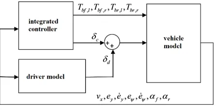
[image:3.612.196.419.338.452.2]Based on the vehicle dynamic model and the driver model, a chassis control system integrating AFS and DYC can be established. The block diagram of the control system is shown in Figure 2:
Figure 2. Control Scheme.
Single-track Model
Simplifying a four-wheel vehicle model, we will get a single-track model. Then the controller is designed. The motion differential equations are as follows:
2 xf 2 xr
mxmy
F F , (13)2 yf 2 yr
my mx
F F , (14)2 yf 2 yr
I
aF bF M, (15)e
, (16)
cos
sin
y
e
y
e
x
e
. (17) Where Fxf ,Fxrare the longitudinal force of the front and rear wheel.Fyf,Fyrare the lateral force of the front and rear wheel. ais the distance from the front axle to the center of mass.b
is the distance from the rear axle to the center of mass. is the yaw rate. Mis the yaw moment.f d c
. (18) According to the equations from Eq. 12 to Eq. 18, the single-track model can be expressed as:
2w
, , ( )
t f t u t w t
. (19) The vehicle’s status parameter is [ , , , , ]Ty
x y e e
,the control input variable is
,
T cu M ,
external input information is
[ ,
,
]
T ol orw
w w
.Predictive Control Problem
To obtain the finite time domain optimization control problem, the Euler method is used to discretize the Eq. 19, we can get:
1
2w
, , ( )
t f t u t w t
, (20)
( ) ( 1) ( )
u t u t u t . (21) The control objective is to achieve the active obstacle avoidance of the vehicle under the control of the correction steering angle and the yaw moment, so the value function is as follows:
1 , ,0
2 2
( ), t Hc t i t t i t i
J t u u u
Q R
. (22) Where
u
tu
t t,,...,
u
t Hc 1,tis optimization variable at time t,H
pis predictive time domain,H
c is control time domain, ,Q Ris weight vector.Solve the following optimization problem at every moment:
min
,
t
t t
u
J
u
. (23)
Constraints:
2
1, , , , , ,..., 1
w
k t f k t uk t k t t Hp
, (24)
, 1, ,
,
,...,
1
k t k t k t c
u
u
u
k
t
t
H
, (25)
1, 1
t t
u u t , (26)
,min , ,max
,
,...,
1
f k t f p
u
u
u
k
t
t H
, (27),min , ,max ,..., 1
f k t f c
u u u k t t H
. (28) Eq. 24 to Eq. 26 are obtained through vehicle dynamics. Eq. 27 is a constraint on the active correction steering angle and the yaw moment. Eq. 28 is the constraint on the increment during continuous sampling time. Assuming =[ ,,..., 1,]
T t t t t Hc t
u u
is the optimal sequence, which are calculated at time t. This sequence is obtained by calculating the optimization problem Eq. 23 which concerned ( ) t at current time and the input (u t1) at previous time. Then using the first sample
t
u
to calculate the optimal active corrective steering angle and the yaw moment. It leads to the state feedback control rule is as follows:,
( ) ( 1) t t
,
t t
u
is the first and the second element of vector
u
t
.The Simulation Tests
In order to verify the performance of the chassis integrated controller, the vehicle’s simulation tests are carried out as the continuous obstacle avoidance on the low adhesion coefficient road. Assuming that the driver's attention is distracted, the vehicle drives on the icy-snowy roadμ=0.3 at the speed of 50 km/h, and there is an obstacle at 60m and 210m. The controller makes the vehicle continually avoid the obstacle by generating active correction steering angle and yaw moment.
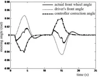
Figure 3 shows that the vehicle successfully avoids the obstacle on the both sides of the road at 60m and 210m. Figure 4 shows that when the driver's attention is distracted, the controller applies a corrective angle to avoid the obstacle actively. When the vehicle completes the obstacle avoidance, the controller no longer produces correction corner, and the driver will have control over the vehicle. Figure 5 shows that in 4 to 6 seconds, the controller needs to give a positive yaw moment, and the vehicle turns to the left. In 15 to 16 seconds, the controller needs to give a negative yaw moment to the vehicle, and the vehicle turns to the right. The yaw angle and rate of the vehicle are shown in Figure 6.
[image:5.612.115.484.295.608.2]
Figure 3. The path of the vehicle. Figure 4. Change of front wheel steering angle.
Figure 5. Change of yaw moment. Figure 6. Change of yaw angle and yaw rate.
[image:5.612.319.485.303.433.2]
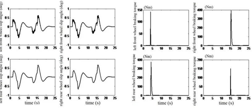
Figure 7. Change of slip angle. Figure 8. Change of braking force.
Summary
This paper designs the controller which integrating the AFS and the DYC based on the MPC theory. The controller has two optimization variables: the active correction angle and the yaw moment. The yaw moment is assigned to four wheels depending on the braking force assignment strategy. Since the controller is designed based on a simplified single-track model, it is not suitable for the vehicles which traveling at a high speed. According to the simulation that the continuous obstacle avoidance on the snowy and icy road, it is verified that the integrated controller can accurately avoid the obstacle on both side of the road, and can improve the vehicle’s handling stability.
Acknowledgement
This work was financially supported by the National Natural Science Foundation of China: Study on the mechanism of a new intelligent electro-hydraulic coupling steering system for commercial vehicle (Project Number 51575047). This work was also financially supported by Beijing Municipal Science & Technology Commission: Key technical research on high-security steering by wire system of Autonomous Vehicle (Project Number Z171100000917023).
References
[1] Boada M.J.L., Boada B.L., Munoz A. et al, Integrated control of front-wheel steering and front braking forces on the basis of fuzzy logic [J], Proceedings of the Institution of Mechanical Engineers, Part D: Journal of Automobile Engineering. 2006, 220: pp. 253-267.
[2] Burgio G., Zegelaar P., Integrated vehicle control using steering and brakes [J], International Journal of Control, 2006, 79: pp. 534-541..
[3] Chen Wuwei, Chu Changbao, Electric power steering system and anti-lock braking system based on layered coordinated control [J], Journal of Mechanical Engineering, 2009, 45(7): pp. 188-193. [4] Yang X., Wang Z., Peng W., Coordinated control of AFS and DYC for vehicle handling and stability based on optimal guaranteed cost theory [J], Vehicle System Dynamics, 2009, 47: pp. 57-79. [5] Wu Jianyun, Tang Houjun, Ouyang T. et al, Improving Vehicle Handling Performance and Stability by Integrated Control of Active Front Steering and Direct Yaw Moment [J], Journal of System Simulation, 2009, 21(5): pp. 1227-1232.
[7] Falcone P., Tseng H.E., Borrelli F. et al, MPC-based yaw and lateral stabilization via active front steering and braking [J], Vehicle System Dynamics,2008,46: pp. 611-628.
[8] Falcone P., Borreli F., Tseng H.E. et al. A hierarchical model predictive control framework for autonomous ground vehicles [C]. Proceedings of the American Control Conference, 2008.
[9] Gao Y., Lin T., Borreli F. et al. Predictive control of autonomous ground vehicles with obstacle avoidance on slippery roads [C]. Proceedings of the Dynamic Systems and Control Conference, 2010.
[10] Gray A., Gao Y., Lin T. et al. Predictive control for agile semi-autonomous ground vehicles using motion primitives [C]. Proceedings of the 2012 American Control Conference, 2012.
[11] Falcone P., Borreli F., Asgary J. et al. A model predictive control approach for combined braking and steering in autonomous vehicles [C]. Proceeding of the Control and Automation Conference, 2007.
[12] Falcone P., Tufo M., Borreli F. et al. A linear time varying model predictive control approach to the integrated vehicle dynamics control problem in autonomous systems [C]. Proceedings of the IEEE Conference on Decision and Control, 2007.
[13] Gray A., Gao Y., Hedrick J.K. et al. Robust predictive control for semi-autonomous vehicle with an uncertain driver model [C]. Proceedings of the IEEE Intelligent Vehicle Symposium, 2013. [14] Gray A., Gao Y., Lin T. et al. Stochastic predictive control for semi-autonomous vehicle with an uncertain driver model [C]. Proceedings of the 16th International IEEE Annual Conference on Intelligent Transportation System, 2013.
[15] Liu C., Gray A., Lee C. et al, Nonlinear stochastic predictive control with unscented transformation for semi-autonomous vehicles [C], Proceedings of the 2014 American Control Conference, 2014.
[16] Gray A., Ali M., Gao Y. et al, Semi-autonomous vehicle control for road departure and obstacle avoidance [C]. IFAC Symposium on Control in Transportation Systems, Sofia, Bulgaria, September, 2012.
[17] Gray A., Ali M., Gao Y. et al, Integrated threat assessment and control design for roadway departure avoidance [C]. Intelligent Transportation Systems Conference, Anchorage, September, 2012.
[18] Gao Y., Gray A., Tseng H.E. et al, A tube-based robust nonlinear predictive control approach to semiautonomous ground vehicles [J]. Vehicle System Dynamics, 2014, 52(6): pp. 802-823.
[19] Boada B.L., Boada M.J.L., Diaz V., Fuzzy-logic applied to yaw moment control for vehicle stability [J]. Vehicle System Dynamics, 2005, 43(10): pp. 753-770.
[20] Shino M., Nagai M., Yaw-moment control of electric vehicle for improving handling and stability [J]. JSAE Review, 2001, 22(10): pp. 473-480.