2017 2nd International Conference on Advances in Management Engineering and Information Technology (AMEIT 2017) ISBN: 978-1-60595-457-8
MIMO Radar Waveform Design for Multi-target ISAR Imaging
Yi-shuai GONG
1,*, Han-yang XU
2, Qun ZHANG
1and Yi-jun CHEN
11
Institute of Information and Navigation, Air Force Engineering University, Xi’an, China
2
School of Electronic Engineering, Xidian University, Xi'an, China
*
Corresponding author
Key words: MIMO radar, Waveform design, the Nearest Neighbor Algorithm, ISAR imaging.
Abstract: Existing MIMO radar waveform design is mostly studied for narrowband signal according to the need of radar tasks like tracking and detection, and the need of imaging task is not considered. A kind of method about MIMO radar waveform design for multi-target ISAR imaging is proposed in the paper. The prior information like target location, RCS, velocity as well as bandwidth limitation of imaging task is considered in waveform optimization as important constraints, there are a waveform optimization model for multi-target imaging is established and is solved by least squares estimation and the nearest neighbor algorithm. The designed waveform can achieve the imaging of the targets in different directions at the same time.
Introduction
MIMO (Multiple Input Multiple Output) radar is a new radar system proposed in recent years, which contains multiple antennas at the transmitter and receiver[1]. According to the distance between the antennas, MIMO radar can be divided into two types, distributed MIMO radar and centralized MIMO radar. The antennas distance of centralized MIMO radar is smaller and the targets echoes received by centralized MIMO are coherent[2]. Therefore, centralized MIMO radar can get good waveform diversity gain by transmitting different signals and can design the transmitting waveforms flexibly according to the practical application[3-4].
Recently, MIMO radar waveform optimization design has become a hot research area and lots of research results have been obtained[5-7]. In [5], an algorithm about using covariance matrix of transmitting waveform to obtain the desired beam pattern has been proposed; In [6], a method about using DFT and toeplitz matrix to design the covariance matrix of transmitting waveform has been put forward; In [7], a method about using matrix weighting to design the transmit beampattern has been raised. However, these algorithms are studied for narrowband signal according to the need of radar tasks like tracking and detection, and the need of imaging task is not considered. Target imaging can provide important target features for target identification, so it plays an important role among the radar tasks. What’s more, during the imaging, the wideband transmitting signal that matches the target features is needed.
Therefore, a method about MIMO radar waveform optimization design for multi-target ISAR imaging is proposed in the paper. Firstly, the prior information obtained by tracking and searching like target location[8-10], RCS[11-12], velocity[13] as well as bandwidth limitation of imaging task is considered as important constraints to establish the waveform optimization model. Secondly, the waveform optimization model is solved by least squares estimation and the nearest neighbor algorithm referring to the [14]. Next, the equations about ISAR imaging by using the designed waveform are derived. Finally, simulations show that the designed waveform can achieve the imaging of the targets in different directions at the same time.
MIMO Radar Signal Model
2
( ) ( )ej f tc ,0
m p
m
s t=x t π ≤t≤T
(1)
… θ
θ θ θ
target
[image:2.612.250.354.93.181.2]dddd
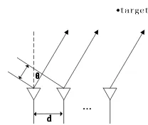
Figure 1. The diagram of MIMO radar field emitter array
where x tm( ) denotes the baseband signal transmitted by the mth element, fc denotes the carrier frequency, Tp is the pulse width. So the transmit signal synthesized in the far field at the angel θ
can be denoted as
1
( )
0
sin 2
sin
( , ) ( ) e ,0
M
m p
m
c md
j f t c
md
s t x t t T
c
θ π
θ θ
− =
+
+ ≤ ≤
∑
=
(2) In practical application, MIMO radar transmits L sub-pulses in a pulse and the pulse width of sub-pulses is Ts, that is Tp =LTs. Thus, the lth baseband signal transmitted by the mth element
can be denoted asxm( )l =xm( ) |t t=(l−1)Ts ,l =1, 2,,L. And the spectrum expression is
1
( )
2 1
/ 2, , / 2 1
( ) ( ) e ,
L
m m
l
j l n
N
Z n x l n N N
π
=
− −
=
∑
= − −(3) where N denotes the number of frequency points, suppose that N=L. Therefore, the spectrum
of discrete baseband signal transmitted by the array can be denoted as
1 2 T
( )n =[Z n Z n( ), ( ), ,ZM( )]n = n
Z Xf , where [1, e j2 n N, , e j2 (L 1)n N]T
n
π
π − −
−
=
f ,X=[x x1, 2,,xM]T
andxm =[xm(1),xm(2),,xm( )L ].
According to the analysis above, at the angel θ the power spectrum of the signal at the frequency fc+nB N can be denoted as
T 2
( ) | ( ) ( ) | /
n n
P θ = a θ Z n N
(4) where
T sin ( 1) sin 2 ( ) 2 ( )
/ 2, / 2 1, , / 2 1
[ ] ,
( ) 1, c , , c
n
nB d nB M d
j f j f
N c N c
n N N N
θ θ
π π
θ
+ + −= − − + − −
= a
e e
(5) denotes the steering vector at the frequency fc+nB N, c denotes the light speed. Therefore, the
beampattern at the angel θ can be denoted as
T
/2 1
2 /2
( ) | ( ) ( ) | /
N n n N
U θ θ n N
−
= −
=
∑
a Z(6)
MIMO Radar Waveform Design
Establishment of Waveform Optimization Model
From the analysis above we can know that at the angel θk the power spectrum of the signal at the
T 2
( ) | ( ) ( ) | /
n k n
P θ = a θ Z n N
(7 ) in which, θk denotes the kth discrete azimuth. According to the approximation of the designed
waveform and desired waveform, the optimization model can be established as follows
2 1
2 { ( )}
1 2
min | ( ) |
s. t . PAR( ) , 0, , 1
m
N K
n k kn x n
k n N
m
P p
m M
θ
ρ
−
= = −
−
≤ = −
∑ ∑
x (8)
in which, K denotes the number of discrete azimuth, pkn denotes the desired power spectrum at
the nth frequency point at the angel θk,
ρ
denotes the pre-set threshold value of PAR . And thePAR of the signal transmitted by the mth element can be expressed as
1
2 2
0
1
PAR( ) max | ( ) | / | ( ) |
N
m m m
n
n
x n x n
N −
=
=
∑
x
(9) In general, suppose the signal transmitted by each element satisfies the energy constraint as follows
1
2
0
| ( ) | , 0, , 1
N m n
x n N m M
−
=
= = −
∑
(10) Thus, the constraint in the optimization model can be expressed as
(
)
2PAR m max | m( ) | , 0, , 1
n x n m M
ρ
= ≤ = −
x
(11) To ensure the designed waveform matches the targets features, we should design the desired waveform combining with the prior information of the targets.
Firstly, beams should be formed in target directions, according to the obtained targets azimuth information. And the power of beams in different target directions can be calculated as follows:
According to the target location, RCS, velocity[8-13] and radar range equation[15]
2 2 3 4
0
/ (4 )
t n n
SNR=PG λ σ π κT B F R
(12) to ensure the echoes from H target directions all can be detected, we assume that the SNRs of echoes received from H target directions all exceed the detection threshold. Therefore, if the transmit power of radar is a fixed valuePt, the desired transmit power in thehth target direction can
be denoted as
4 1
4 4
1 1
4 1 1
t h
th H
h h h h
P R
P
R R
R
σ
σ σ
σ
=
= ⋅
∑
(13) in which,
σ
h denotes the RCS of the target in the hth target direction, Rh denotes the distancebetween the radar and the target in the hth target direction.
Secondly, we should design the bandwidth of transmit signal synthesized in each target direction. In general, we consider that the target velocity, motion direction and distance from the target to the radar reflect the target threat degree. We define the target threat degree as follows
1/ sin
max(1/ ) max( ) max(abs(sin ))
h h h
h
h h h
R V
R
υ
ϖ
υ
ϖ
= + +
(14) where υh denotes the velocity of the target in the hth target direction, ϖhdenotes the motion
The target with higher threat degree and smaller size needs higher range resolution ρr. We can
set a fixed low range resolution {
ρ
rh0}Hh=1 for the targets in different directions at first. Thus we canget the approximate size of targets in range direction. The experience shows that if the range resolution ρr is less than or equal to the one-fiftieth of target size in range direction, good imaging
results will be obtained. Therefore, the range resolution of the target in the hth target direction can be denoted as
50 1
50 1
h h
rh
h h h
S V
S V V
ρ
= ≤>
(15)
where Sh denotes the approximate size in range direction of the target in the hth target direction. So the bandwidth of transmit signal synthesized in the hth target direction can be denoted as
2
h rh
B =c ρ
(16) To distinguish the echoes from different target directions, transmit signal synthesized in each target direction should distribute in orthogonal frequency band.
Finally, from the analysis above, we can get the number of frequency points occupied by the transmit signal synthesized in the hth target direction is Nh =round B N B( h / ) and 1
H
h= Nh N
∑ = .
In the h th target direction, make the desired transmit power Pth evenly distribute at Nh
frequency points, thus we can get the desired transmit power spectrum in the hth target direction, that isphn.
Solution to the Waveform Optimization Model
Referring to the solution algorithm in [14], we divide the solving process into two stages.
Stage 1: By introducing the instrumental variable{φkn}, the waveform optimization problem can be converted to
T
2 1
2 { }
1 2
( ) ( )
min | ( ) e kn|
m
N K
j
n k kn
Z k n
n N
Np
n φ
θ
−
= =−
−
∑ ∑
a Z(17 ) Then Eq. 17 can be written as
2 1
2 { ( )}
2
min || ( ) ||
m
N
n n
Z n n N
n −
=−
−
∑
A Z b(18)
where T T T 1 T
1 1
[ ( ) ( )] , [ ej n ejKn]
n n n K n Npn NpKn
φ φ
θ θ
= =
A a a b .
This optimization model can be solved by the iterative algorithm and least squares estimation . Stage2: According to the {Zm( )}n obtained from Stage 1 and taking the phase ambiguity into consideration, we can establish the optimization model by introducing the instrumental variable {ψn}.
2 1 ( 1)
2 2 2
{ ( )} 2
min || ( ) e [1e e ] ||
s. t . PAR( ) , 0, , 1
n m
N n N n
j j
j N N
x n n N
m
n
m M
π π
ψ
ρ
− −
− −
=−
−
≤ = −
∑
x
Z X
(19)
ISAR Imaging Based on Designed Waveform
From (2), the transmit signal of MIMO radar can be denoted as
1 1
( 1) sin
( , ) ( ) 0
H M
h
m p
h m
m d
s t s t t T
c
θ
θ
= = − =∑∑
+ ,≤ ≤ (20) So the echoes received by the radar can be denoted as1 1
( 1) sin 2 ( )
( , ) ( )
c
H M
h hi l
r hi m
h m i
m d R t
s t s t
c
θ
θ
σ
= = − =∑∑∑
+ − (21) where tl denotes the slow time, R thi( )l denotes the distance between the ith scattering point of the target in the hth target direction and the radar at tl,σ
hi denotes the RCS of the ith scattering point of the target in the hth target direction.Suppose that motion compensation has been achieved. Because the transmit signal synthesized in each target direction should distribute in orthogonal frequency band, from the analysis above, we can separate the echoes from different target directions. Thus the echoes from the hth target direction can be denoted as
1
( 1) sin 2 ( )
( ) ( )
c
M
h hi l
rh hi m
m i
m d R t
s t s t
c θ σ = − =
∑∑
+ − (22) In range direction, matching filtering is used. So the one-dimension range profile can be denoted as 2 2 4 2 ( ) 2 1 2( ) psf( )
hi hc
hi hi l
c hi
hc hc
x x X
I x vt
j f y
hi c Y Y
rhP hi i
y
s t t e
c π σ + − + − = =
∑
− (23) where(xhi,yhi) is the coordinate of the ith scattering point of the target in the hth target direction relative to the reference point (Xhc,Yhc).Finally, we can get the two-dimension imaging result by doing FFT on Eq. 23 in azimuth direction
( )
2 2 4 ( ) 2 2 1 2 4psf( ) 4 ( )
hi hc hi c hi
hc
x x X I
j f y
hi c Y c hi
rhP hi
i hc
y f x v
s t t e f
c Y
π
σ π δ
+
− +
=
=
∑
− −(24)
in which, ( )1 2 ( )
1
( 1) sin
psf( ) F [| ( ) | ], ( ) F [ ( )].
M
h
h h m
f f
m
m d
t S f S f s t
c θ − = − = =
∑
+Simulation and analysis
Suppose the array is consisted of ten linearly spaced isotropic emitter array elements and the inter-element spacing is d =0.5* / (c fc+B/ 2). The carrier frequency is 10
c
f = GHz, the number
of sub-pulses is L=400 and the number of frequency points is N =L=400, the number of
discrete azimuth is K =181. The transmit power of radar is P =8000W . And the information obtained by like tracking and detection is shown in Table 1.
Table 1. Targets parameters.
targets azimuth distance( )m RCS velocity(m s/ ) course
target 1 −20 15000 3 300 −20
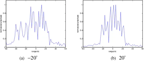
Firstly, we set the range resolution in −20 and 20 is 2m, that is
1 0
2
{ρrh }h= =2m. So the bandwidth in the two directions is 75MHz. Through the simulation, the coarse resolution range profiles of targets in −20and 20 are shown in Fig.2. And from the Fig.2(a), we can get the
approximate size of target in −20 is
1 65
S = m. From the Fig.2(b), we can get the approximate
size of target in 20 is
2 40
S = m. What’s more, according to the Eq 14,15,16 and Table 1, we can
get the required range resolution in −20 and 20 is
1 1.3
r m
ρ = ,
2 0.4
r m
ρ = , the required
bandwidth in −20 and 20 is
1 115 MHz
B = ,
2 375 MHz
B = . So the number of frequency
points occupied by the transmit signal synthesized in the −20 and 20
are 94 and 306 respectively. And according to the Eq 13 and Table 1, we can get the desired transmit power in the two target directions are 2952W and5048W.
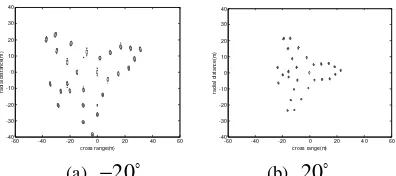
The 3D plot of designed waveform is shown in Fig.3. The beams are formed in target directions and distribute in orthogonal frequency band. The scattering models of planes in target directions are shown in Fig.4. And Fig.5 shows the imaging results by designed waveform, Fig.6 shows the imaging results by LFM signal. In general, we use the PSNR (Peak Signal to Noise Ratio)[16] to measure the image similarity. The more similar, the value of PSNR is larger. Through the calculation, we can get the PSNR of Fig.5(a) and Fig.6(a) is 35.31, the PSNR of Fig.5(b) and Fig.6(b) is 34.72. So the imaging result of designed waveform is similar to the imaging result of LFM signal, which is usually used in radar imaging. Therefore, the availability of the algorithm proposed in the paper is proved.
[image:6.612.147.452.320.731.2](a) −20 (b) 20
[image:6.612.154.455.323.450.2]Figure 2. The range profile in target directions.
Figure 3. The 3D plot of designed waveform.
(a) −20
(b) 20
Figure 4. Scattering model in target directions.
-60 -40 -20 0 20 40 60
0 0.2 0.4 0.6 0.8 1
range(m)
n
o
rm
a
li
z
e
d
a
m
p
li
tu
d
e
-60 -40 -20 0 20 40 60
0 0.2 0.4 0.6 0.8 1
range(m)
n
o
rm
a
li
z
e
d
a
m
p
li
tu
d
e
-60 -40 -20 0 20 40 60
-40 -30 -20 -10 0 10 20 30 40
cross range(m)
ra
d
ia
l
d
is
ta
n
c
e
(m
)
-60 -40 -20 0 20 40 60
-40 -30 -20 -10 0 10 20 30 40
cross range(m)
ra
d
ia
l
d
is
ta
n
c
e
(m
[image:6.612.166.443.608.726.2](a) −20
[image:7.612.213.411.69.157.2](b) 20 Figure 5. Imaging results by designed waveform.
[image:7.612.209.417.183.277.2](a) −20 (b) 20
Figure 6. Imaging results by LFM signal.
Conclusion
A kind of method about MIMO radar waveform design for multi-target ISAR imaging is proposed in the paper. The prior information obtained by detection and tracking, like target location, RCS, velocity as well as bandwidth limitation of imaging task is considered in waveform optimization as important constraints. And a waveform optimization model for multi-target imaging is established and is solved by least squares estimation and the nearest neighbor algorithm. The beams are formed in target directions and are match the target features. The simulation shows that the designed waveform can achieve the imaging of the targets in different directions at the same time and possess the good imaging result.
Acknowledgment
This work was supported by the National Natural Science Foundation of China under Grant 61631019.
References
[1] H.J. Wang, H.B. Xu, M. Lu, C.L. Huang. Technology and Application Analysis of MIMO Radar[J].Radar Science and Technology, 2009, 7(4): 245-249.
[2] Y. Qiang, G.J. Zhang, B. Li. Development and Application of MIMO Radar[J]. Fire Control Radar Technology, 2010, 39(1): 1-10.
[3]J. Li and P. Stoica. MIMO Radar with Colocated Antennas[J].IEEE Signal Processing Magazine, 2007, 24(5): 106-114.
[4] P. Stoica, J. Li, and Y. Xie. On Probing Signal Design for MIMO Radar[J].IEEE Transactions on Signal Processing, 2007, 55(8): 4151-4161.
[5] S. Ahmed, J.S. Thompson, Y.R. Petillot, B. Mulgrew. Unconstrained Synthesis of Covariance Matrix for MIMO Radar Transmit Beampattern[J].IEEE Transactions on Signal Processing,2011, 59(8): 3837-3849.
[6] J. Lipor, S. Ahmed and M.S Alouini. Fourier-based Transmit Beampattern Design Using MIMO Radar[J].IEEE Transactions on Signal Processing, 2014, 62(9): 2226-2235.
cross range(m)
ra
d
ia
l d
is
ta
n
c
e
(m
)
-60 -40 -20 0 20 40 60 -40
-30 -20 -10 0 10 20 30 40
cross range(m)
ra
d
ia
l
d
is
ta
n
c
e
(m
)
-60 -40 -20 0 20 40 60 -40
[7] S. Ahmed and M.S Alouini. MIMO Radar Transmit Beampattern Design without Synthesising the Covariance Matrix[J].IEEE Transactions on Signal Processing, 2014, 62(9): 2278-2289.
[8] S. Gao. Target Orientation Problem of Radars[J].Fire Control & Command Control, 2003, 28(4):0042-0044.
[9] W. Wang, C.P. Wang, X. Li. Multi-target Localization and Estimation of Mutual Coupling Bistatic MIMO Radars[J].Journal of Huazhong University of Science and Technology (Natural Science Edition), 2012, 40(7):0078-0083.
[10] C. Gu, J. He, H. Li and X. Zhu. Target Localization Using MIMO Electromagnetic Vector Array Systems[J].Signal Processing, 2013, 93(7): 2103-2107.
[11] M. Xu, H.B. Wang, C. Wang, Q.Q. Zhao, J.S. Zhang. A Method of RCS Estimation Based on Air Surveillance Radar[J]. Modern Radar, 2014, 36(3):11-15.
[12] R. Lambour, T. Morgan, N. Rajan N.Assessment of Orbital Debris Size Estimation from Radar Cross Section Measurements[J].Advances in Space Research, 2004, 34(5):1013-1020.
[13] S.H. He, C.S. Zhang, J. Zhang. Study on Real-Time Unambiguous Estimation of Target Velocity for Stepped-Frequency Linear Frequency-Modulated Pulse Radar[J]. Journal of Hunan University (Natural Science Edition), 2011, 38(5):0059-0063.
[14] H. He. Wideband MIMO Systems: Signal Design for Transmit Beampattern Synthesis[J]. IEEE Transactions on Signal Processing, 2011, 59(2):618-628.
[15] L.F. Ding, F.L. Geng. Radar Theory[M]. Beijing: Publishing House of Electronics Industry, 2009: 222-223.