2017 2nd International Conference on Artificial Intelligence and Engineering Applications (AIEA 2017)
ISBN: 978-1-60595-485-1
Study on Visual Servo of Space Manipulator with
Time-delay
PEI ZHANG and XIN LIU
ABSTRACT
With the development of vision technology, visual servo technology of robot has been becoming a hot point. The real-time image processing is one of the key factors that affect the performance of visual servo. Time-delay of image processing is common in space robot manipulator which has to use high reliable but low performance processors. The delay of image may cause vibration of space manipulator’s end effector. In this paper, the influence of image processing delay is analyzed by simulation of a 4-DOF space manipulator. A visual servo method based on subdivision control is proposed. Its effectiveness of enhancing control accuracy and system stability is verified by simulation.
KEYWORDS
Space Manipulator, Visual servo, time-delay.
INTRODUCTION
With the development of visual technology [1], visual servo of robot has been drawing wide attention all over the world. It has been applied gradually both on ground and in space [2, 3, 4]. Visual servo can be divided into two categories: the first one is based upon acquiring the position information of the manipulator’s end effector. The second one is based upon comparing the image acquired with the desired image [5,6,7]. For both servo methodologies, the accuracy and instantaneity of image processing are the key factors that affect the control performance significantly.
It is possible to acquire accurate and fast image by adopting image processor with high performance on ground. As a result, the study on the influence of image inaccuracy and time-delay lacks concern in industrial area. Different from manipulators operating on ground, it is impossible to equip space manipulators with industrial chips of high performance, instead, chips of low performance but high reliability have to be used, which often bring obvious time-delay of processing image. In addition to this, the stiffness of space manipulators is relatively low because of weight restriction, which exaggerates the influence of time-delay. As discussed above, time-delay of visual servo has to be taken into consideration in the control of space manipulator.
The effects of visual servo time-delay on space manipulator are discussed in this paper. SectionⅡshows the effects of visual time-delay through simulation of a 4-DOF manipulator. Section Ⅲ analyzes the stability of visual servo model. Section Ⅳ
proposes and verifies a subdivision control law for visual servo system with time-delay which is based on closed-loop control of joint angle. Section Ⅴ summarizes the study of this paper.
SIMULATION WITH VISUAL TIME DELAY
The target of space manipulator’s visual servo system is to guide its end effector to reach desired position accurately. The Cartesian coordination of manipulator’s task position is provided by camera installed on the end effector. The controller can plan the desired velocity of end effector and make it approaching desired position in line. The space manipulator discussed here consists of four joints, as shown in Fig. 1:
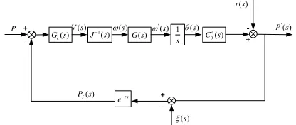
The block of visual servo system is shown in Fig. 2, P(s) is the desired orientation.
( ) ( ) ( ) ( )
Tx s y s z s s
P(s) .P (s)' is the orientation of end effector,
f
P (s) is the measured orientation output by end camera. J (s)-1 is the inverse Jacobian
matrix of manipulator. G(s) is the transfer function of joint’s velocity, andG (s)c is a proportional controller of joint angular velocity.V(s)is the planned velocity of end effector. The joint angle velocity isω (s)' , integration of which is the joint’s angle.
4 0
C (s) is the transformation of end effector’s orientation from joint coordinate to Cartesian coordinate.r(s) represents the disturbance on end effector’s orientation by visual servo time-delay. is the delay time. ξ(s) is the error of visual measurement.
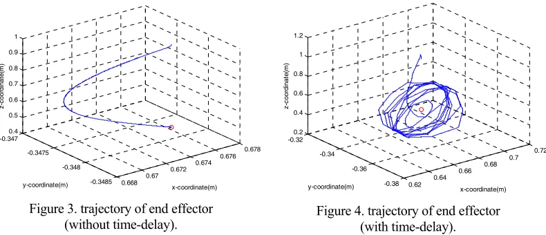
Since the accuracy and instantaneity of visual measurement plays a key role in control accuracy of visual servo system, we compared simulation results with different assumptions. Fig. 3 shows simulation result without visual time-delay. Fig. 4 shows simulation result with visual delay of 4 seconds. The joints’ angle of initial configuration for both simulation are 6.0839 114.6486 144.8824 59.7662 , the desired orientation of end effector was0.675m 0.348m 0.474m 90. If the distance
[image:2.612.101.268.550.653.2]between the end effector and desired position is less than 5mm, the manipulator can be considered as arriving at destination.
Figure 1. Space Robot Manipulator.
( )
c
G s 1( )
J s G s( ) 1
s
4 0( )
C s
s
e
P V s( ) ( )s ( )s P s'( )
( )
f
P s
( )
r s
( )s
'( )
[image:2.612.285.493.555.643.2]s
0.668 0.67
0.672 0.674
0.676 0.678
-0.3485 -0.348 -0.3475 -0.3470.4
0.5 0.6 0.7 0.8 0.9 1
x-coordinate(m) y-coordinate(m)
z-co
or
di
na
te
(m
[image:3.612.105.500.63.233.2])
Figure 3. trajectory of end effector (without time-delay).
0.62 0.64
0.66 0.68
0.7 0.72
-0.38 -0.36 -0.34 -0.320.2
0.4 0.6 0.8 1 1.2
x-coordinate(m) y-coordinate(m)
z-coordi
na
te(m
)
Figure 4. trajectory of end effector (with time-delay).
For the simulation without time-delay, the distance between end effector and desired position is reduced to less than 5mm, and the manipulator finally arrives at the desired position. As for the simulation with time delay, the manipulator can’t arrive at the desired position and the motion scope range of X coordinate axis is from 640 to 710mm, the motion scope range of Z coordinate axis is from 450 to 510mm, the manipulator finally oscillated along an ellipse trajectory. That is because the stability of visual servo system is exaggerated by time delay of visual measurement, so motion oscillation is stimulated by disturbance of ( )r s .
STABILITY ANALYSIS OF VISUAL SERVO SYSTEM
To analyze the system stability, the system model has to be linearized near the point of desired position. For analyzing convenience, the desired orientation is assumed as P0 [0 0 0 0], the motion of manipulator during t is V't, the
orientation of end effector is described as:
t t
' ' '
0
P P V V (1)
'
V is the velocity of end effector. J0is the Jacobian matrix when the manipulator reached desired position and it is considered as a constant matrix. Since J0 is constant, and both G(s)and G (s)c in Fig.2 are diagonal, we obtain:
' -1 '
0 0 c
'
P (s) = J J G(s)G (s)(P(s) - P (s)) K
= G(s)(P(s) - P (s)) s
(2)
K is the proportional factor of velocity controller G (s)c . Joint model of G(s) can
( )
x s x s'( )
1
s
ts
e
K g sT( )
j
'
[image:4.612.112.481.55.138.2]j N
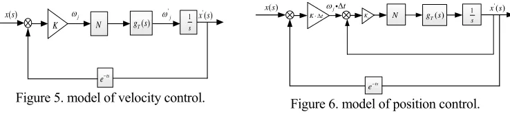
Figure 5. model of velocity control.
( )
x s '( )
x s
1
s
ts
e
Kt Kc g sT( )
j t
N
Figure 6. model of position control.
The linearized block of visual servo system is shown in Fig. 5. g sT( ) is the transmission model of joint, of which the input is motor velocity and the output is joint’s angular velocity.
The dynamic model of joint has many non-linear characteristics such as joint clearance, non-linear stiffness, joint damp and so on[9]. Because of these non-linear characteristics which would influence the system stability[10], it is usually to control the motor speed instead of the joint angular velocity because the reduction ratio is constant[8]. To obtain the transfer function of joint angular velocity, the closed-loop control transfer function of motor speed is neglected since the transection time of motor’s speed is largely less than that of joint’s angular velocity. The transfer function is described as:
' 2
2 2 2 2
( )
( ) ( )
( ) T
s N K K
g s N g s
s N Js N K Js K
(3)
Nis reduction ratio, Kis joint stiffness, J is load inertia. ( )g s is a second-order
oscillatory function with two poles of which real part is zero. These two poles exaggerate the phase performance of open-loop system, and made it unstable in high frequency. When there is disturbance or measuring error, the system would oscillate as shown in Fig 4.
To improve system stability, a visual servo system with closed-loop control of joint angle is proposed in this paper. The system’s stability is improved by the rectification of the transfer function of joint’s transmission.
It is assumed that desired joints’ angular velocity is unchanged during t, so the
referred joint’s angle displacement is described ast, which also is the reference
input of closed-loop control of joint angle. The block of visual servo system based on closed-loop control of joint angle is shown in Fig. 6. Kcis the coefficient of joints’
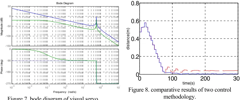
position controller. The bode plots of open-loop represented by blue curves are shown in Fig. 7. There is a crossing point in high frequency section of the plot which makes the system unstable. The bode plots of the rectified system represented by green cures are shown in Fig. 7. Because of that gT
s is rectified by position controller, there isBode Diagram
Frequency (rad/s)
10-3 10-2 10-1 100 101 102 103
-270 -180 -90 0
P
has
e (
deg)
-150 -100 -50 0 50
M
agn
itu
de (
dB
[image:5.612.111.509.64.229.2])
Figure 7. bode diagram of visual servo.
0 100 200 30
0 0.2 0.4 0.6 0.8
time(s)
di
st
anc
e(
m
)
Figure 8. comparative results of two control methodology.
SIMULATION BASED UPON CLOSED-LOOP CONTROL
In this paper, a subdivision control law is adopted in visual servo control based upon closed-loop control of position. The reference input is the distance from terminal point to desired position, if the distance is longer than a predefined value, the system is in joint’s velocity control mode, when it is shorter than the predefined value, the system is switched into joint’s angle control mode. This control law can enhance both motion accuracy and stability of manipulator when the manipulator is approaching desired position.
The simulation results of visual servo system based upon closed-loop control of position with the same initial condition as in figure 4 are shown in Fig. 8. When the distance between end effector and desired position is shorter than 10mm, the control mode is switched from velocity control to position control. To better observe the effects of subdivision control law, the simulation results of subdivision control and the control only based upon closed-loop control of joint angle velocity are both put in Fig. 8 in which the blue curve represents the former one and the dotted curve represents the latter one. The distance error of subdivision control system based upon closed-loop control of joint angle is obviously less than that of system based upon closed-loop control of joint angle velocity.
SUMMARY
Time-delay of visual measuring commonly exists in visual servo system of space manipulator. When the end effector of manipulator is away from desired position, the influence of time-delay is unobvious, but when manipulator is approving desired position, oscillation would be stimulated by disturbance as system stability is exaggerated by time-delay.
ACKNOWLEDGEMENTS
ZHANG Pei, received the M.Eng degree in China Academy of Space Technology, in 2007. His current research interests include space manipulator control and satellite power system control.
This work was financially supported by National Natural Science Foundation of China (61573058).
REFERENCES
1. Yuan Kui, Lu Peng. State of the Art of visual information processing technology of autonomous robot [J]. High Technology of Communication, 2008, 18(1): 104-110.
2. Zhao Qingbo, Zhao Dean. Vision servo Control System of Fruit Harvesting Robot [J]. Journal of Agricultural Journal, 2009, 40(1): 152-156.
3. Yang Tangwen, Gao Lining. Visual servo technology for coordinated manipulation of a mobile dual-arm manipulator system [J]. Control Theory and Applications, 2015, 32(1): 245-249.
4. Zhang Guoliang, Wang Jie. Wide Range Visual Servo Method Applied to Space Robot [J]. Journal of Xi’an Jiaotong University, 2009, 43(1): 85-89.
5. Dong Zhi-dan, Liu Shi-rong, Jiang Hong-chao. Visual servo Control of a 6-DOF Robot Manipulator Based on Image Moments and Vector Produc t[J]. University of Shanghai for Science and Technology, 2013, 35(13): 221-226.
6. Zhang QiZhi, Ge XinSheng. Visual Servo Control for Un-calibrated Robotic Arm [J]. Journal of Dynamics and Control, 2004, 2(2): 56-59.
7. Wu Bo, Li Hui-guang. Image-Based Direct Visual Servo Controller Design and Simulation [J]. Journal of System Simulation, 2007, 19(22), 5214-5221.
8. Yu Dengyun, Pan Bo, Sun Jing. A Literature Review on Dynamic Modeling and Analysis of the Joint in Space Manipulator [J]. Spacecraft Engineering, 2010, 19(2): 1-10.
9. Liu Zhi-quan, Wei Qing-qing, Wang Yao-bing. Detailed Joint Dynamics Modeling and Joint Torque Control System of Space Manipulators [J]. Journal of Astronautics, 2014, 35(6): 663-668. 10. Zhang Qi, Liu Zhen. Parameters Identification of Flexible Joints with Harmonic Driver [J].