2018 International Conference on Modeling, Simulation and Optimization (MSO 2018) ISBN: 978-1-60595-542-1
Design and Implementation of Wireless Communication
System for Weapon Setting
Bo ZHAO
1,2, De-qiang LI
1,2, Li-wei MA
1,2, Jing WANG
1,2,
Yi QIU
1,2and Jia-bao WEN
1,21Beijing Aerospace Automatic Control Institute, China 100854
2National Key Laboratory of Science and Technology on Aerospace Intelligence Control, China, 100854
Keywords: Weapon setting, Wireless communication system, CC2510.
Abstract. For the weapon system, in order to improve the setting speed, and to set parameters to
multiple shells at one time, the wireless communication system is designed and implemented with CC2510 chip. The composition and function of the system and the design of the software are introduced. The performance of the designed system was verified by experiments. The wireless system can set the information to the weapon well and it is faster compared to the cable setting method.
Introduction
Before launch, the weapon must be set by the control device on the launch vehicles. It is hard to set multiple shells at a time in the cable set method, because of plugging the cable between various devices. it is more convenient and more efficient to set the messages to the weapons in the wireless setting method. The design of the wireless communication system is based on the SimpliciTI communication protocol. The experiment showed that the functions and performance of the wireless communication system can meet the need of the firing rapidly.
The Design of the Wireless Setting System
Based on the needs of setting the weapons, the paper puts forwards the functions, the capabilities and the structure of the wireless setting system. The software works are designed based on the SimpliciTI communication protocol which is chosen according to the need of the setting the weapons.
Function and Composition
In order to save the time of setting the weapons, realize setting multiple shells at a time and improve the reliability, the wireless setting system are design following functions:1) Working immediately after the boot. For convenience, the wireless communication network is connected automatically after the power is on.2) The communication being tested by the users through the ground control devices. 3) Transmitting the setting information to various missiles at a time from the ground devices.4) Jumping to other channels when the current channel is implemented by the noise.
For setting multiple shells at a time, the structure of the wireless setting system is star network. The structure of the wireless communication system is showed as figure 1. The A module is the center of the star network, which is connected with the ground device by cable; The Bi module is connected with the missile controller through a cable, each Bi communicate with A through the air, but the Bi modules doesn’t communicates with each other.
receives a piece of information successfully, a feedback message is returned to the ground devices. The users determine whether the setting is completed, by reading the feedback message on the launch vehicles devices.
Figure 1. The structure of the wireless setting system.
The Analysis of the Wireless Setting System’s Requirements and the Selection of the Communication Protocol
According to the requirements of the weapon setting, the wireless communication has the following features:1) It requires that the transmission speed of the system is more than 100kbps. There are a few setting data such as the launch point coordinates, the target point coordinates, the range of the weapon and some other parameters, so 100kbps can meet the need of the wireless communication system.2) The maximum distance of the wireless communication between the modules on the missiles and the ground should be more than 3 meters.3) In order to set 8 shells at a time, there are at least 9 nodes in the communication network, including 1 node on the launch vehicles and 8 nodes on the missiles.4) Due to the limited power supply capacity, the power consumption of the wireless module on the missile should be less than 300mw.5) The wireless transmission should be safe and reliable and there should be some anti-interface measures of the wireless communication system.6) Because the space is limited, the wireless module on the missile is required to be as small as possible.7) The wireless module on the missile will be launched with the weapon, which can not be recycled, so the cost of the wireless module should be as low as possible.8) For developing the system in a short time, it is better to choose a simple communication protocol.
Because the wireless system needs that the transmission distance is short, the transmission rate is low, the power consumption is low, the cost is low, the short distance wireless communication protocols fits the system. The short distance communication protocols include: Wi-Fi, Bluetooth, UWB, ZigBee and SimpliciTI. Compare the requirement of the wireless communication system with the various protocols, as shown in table 1, and select the appropriate protocol as the basis of the development.
Missile 1
Missile N
The device on the ground
Module
A
Module B1
Missile controller 1
Module BN
Table 1. Comparison of the requirement of th wireless communication system and the various short range communication portocal[1][2][3][4].
sequence The requirement of the wireless communication system
The parameters of the protocol remark
Sim plic iTI
Wi
-Fi bluetooth UWB Zigbee
1. The transmission rate should be more than 100kbps. 50 0k bp s 54 Mb ps 1Mb
ps 110Mbps 250kbps All the protocols can satisfy the requirement about the transmission rate.
2. 300mW
The power consumption of the wireless module on the missile should be less than 300mW
10 0 m w
700
mw 100mw 750mw 100mw Wi-Fi and UWB can’t satisfy the requirement about the power consumption
3. The maximum of transmission distance should be more than 3m. 10 -1 00 m 100
m 10m 10m 10-100m All the protocols can satisfy the requirement about the transmission distance.
4. All the nodes in the network should be more than 9.
10
0 256 8 8 >65000 Bluetooth and UWB protocols can’t satisfy the requirement about the number of the network. By comparison, the SimliciTI and the Zigbee can meet the requirements of the wireless setting system. The two protocols have the same physical layer protocol as the 802.15.4 protocol. The Zigbee protocol was issued by IEEE. The international standards have the good universality and the good compatibility, but it will be high cost, long term and not flexible enough to develop the system. The SimpliciTI were issued by the TI company to improve the lack of the international standards. The SimpliciTI protocol has advantages as good flexibility, low cost and ease of develop. In summary, the SimpliciTI communication protocol fits the wireless setting system best, so the SimpliciTI is chosen to develop the system.
Based on the SimpliciTI protocol, there are 3 types of equipment, they are End Devices(ED), Access Points(AP) and Range Extenders(RE). the hardware structure of the ED is the same as that of the AP[5]. The main function of AP is to manage the network, including storing and forwarding the data, encryption and frequency hopping. The ED is only to forward the messages without any other processing[6].
Based on the SimpiliciTI protocol, the wireless setting system is developed with the CC2510 chip as the core.
Software Design
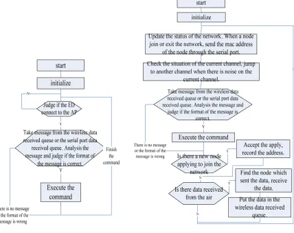
To realize the function of the wireless setting system, the following software processes are designed, checking the network topology after boot, updating the network status, checking the communication between the missiles and the ground, transferring the setting data. The working flows of the AP and ED are showed in the figure 2 and figure 3.
The Results of the Experiment
The Test of the Function and the Performance
In the experiment, the star network consists of an AP and 8 EDs. The baud rate of the serial port is 115200, there are 8 data bits and 1 stop bit in a format, the transferred and received data are displayed in HEX. The experiment results show that the system can realize the following functions: checking the topology of the network after the power is on, updating the status of the network, checking the communication between the missiles and the devices on the launch vehicles, transferring the setting data from the devices on the launch vehicles to the missiles.
[image:4.612.97.525.190.529.2]
Figure 2. Work flow of the ED. Figure 3. Work flow of the AP.
It takes at most 3s to connect the network of the wireless setting system from the boot. The user can see the topology of the network on the computer connected to the AP. The AP can transfer setting data to multiple EDs at a time, the transmission speed is about 500kbit/s.
Because of being on the missiles, the power consumption of the ED nodes is limited. Measuring the power of the wireless setting system, the voltage is 5V, the working current is 25mA. Due to P=U*I, the working power P=125mW, which is lower than the power of other devices on the missiles.
Table 2. The result of the measurement of the wireless system. Communication
distance (m) RSSI value(dB)
0.4 -80
0.5 -86
0.8 -94
1 -96
1.2 -97
2.2 -105
2.5 -105
3.5 -106
The Comparison between the Requirement of the Performance and the Results of the Experiments
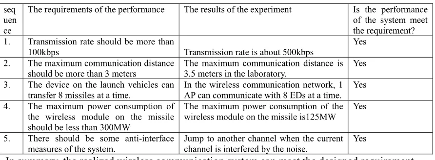
About the wireless setting system, the comparison between the results of the experiment and the index of the performance, is showed in table 3.
Table 3. The comparison between the requirement of the performance and the results of the experiments. seq
uen ce
The requirements of the performance The results of the experiment Is the performance of the system meet the requirement? 1. Transmission rate should be more than
100kbps Transmission rate is about 500kbps Yes 2. The maximum communication distance
should be more than 3 meters The maximum communication distance is 3.5 meters in the laboratory. Yes 3. The device on the launch vehicles can
transfer 8 missiles at a time. In the wireless communication network, 1 AP can communicate with 8 EDs at a time. Yes 4. The maximum power consumption of
the wireless module on the missile should be less than 300MW
The maximum power consumption of the wireless module on the missile is125MW
Yes
5. There should be some anti-interface
measures of the system. Jump to another channel when the current channel is interfered by the noise. Yes
In summary, the realized wireless communication system can meet the designed requirement.
Summary
The wireless setting system is designed based on SimpliciTI and chip CC2510. The wireless network is connected after boot, and the device on the launch vehicles can transfer setting data to various missiles at a time. The wireless module will Jump to other channels when the current channel is implemented by the noise. The results of the experiments show that the small range, low power consumption, low rate wireless communication network can transfer the setting information. Compared to the cable setting ways, it spends less time with the wireless communication system.
References
[1] Texas Instruments Inc. CC253x Datasheet [C] 2007.
[2] The Institute of Electrical and Electronic Engineers. IEEE Standard for Information Technology 802.15.4 [C] 2003.
[3] Cheng Rui Jiang Dezhong The Design of Wireless Test Lanch and Control System Based on Zigbee Technology [J], Aerospace Control. Apr. 2011.
[image:5.612.85.531.278.442.2]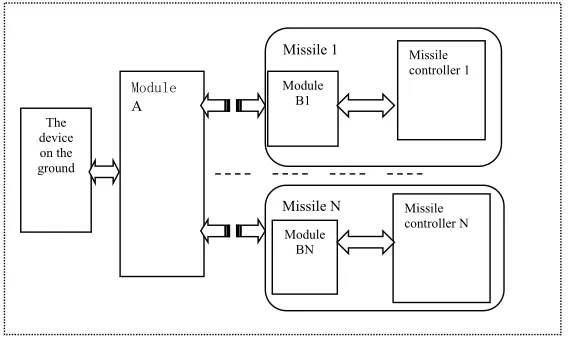
![Table 1. Comparison of the requirement of th wireless communication system and the various short range communication portocal[1][2][3][4]](https://thumb-us.123doks.com/thumbv2/123dok_us/277215.1028181/3.612.91.521.92.334/table-comparison-requirement-wireless-communication-various-communication-portocal.webp)