2016 International Congress on Computation Algorithms in Engineering (ICCAE 2016) ISBN: 978-1-60595-386-1
1 INTRODUCTION
Prestressed tension hydraulic system has been widely used in bridge, railway and road construction fields. According to the results of plenty of detections to the road and bridge in service, the potential safety hazard is mainly caused by the low prestress precision. Tradi-tional tension system consists of the hand-operated servo valve controlled hydraulic system and, the pre-stress precision is mainly regulated by the operator which finally degrades the construction quality. Some research institutions are thus focused on the realization of the automatic prestressed tension hydraulic system to guarantee the tension quality. Up to now, most au-tomatic hydraulic tension systems in research could be classified as two types: the valve-controlled one [1, 2] and the pump-controlled one [3]. For the aspect of the energy efficiency and requirement about the cleanli-ness of construction environment and the equipment size, the pump controlled system is of better develop-ment prospects than the valve-controlled system. However, in the pump-controlled system, some obvi-ous drawbacks such as the slow response speed and
the poor persistence ability on external disturbance also exist which need an appropriate controller to compensate.
Usually, the controller design is based on the hy-draulic system model. As many parameters such as the bulk modulus coefficient and the elements’ damping coefficient cannot be obtained during the operation process, the deduced model couldn’t represent the real system’s characteristics well. Therefore, the real sys-tem is identified to analyze its property before the controller design. During this process, an appropriate identification algorithm largely determines the model precision. Although modern system identification methods based on common artificial intelligence theo-ries such as the neural network algorithm, genetic algorithm, particle swarm optimization algorithm, differential evolution algorithm have solved some identification problems [4, 5], drawbacks such as the small sample estimation, high-dimensional optimiza-tion problems, algorithm structure selecoptimiza-tion and so on still cannot be resolved which finally hinder their practical engineering application.
On the contrary, the SVR identification method
Prestressed Tension Hydraulic System Identification Using Linear
Programming Support Vector Regression
Wenfeng Li1, Qiang Liao1, Minjian Xu1, Xiaohu Li2 & Songwei Liu2 1
Chongqing Communications Technology Research & Design Institute, Chongqing, China
2School of Mechanical Engineering, Xi’an Jiaotong University, Xi’an, Shaanxi, China
ABSTRACT: Prestressed tension hydraulic system has been widely applied in many construction engineering fields. Getting an accurate mathematical model for this system could improve its control properties largely. For the common derivation model, many parameters related with oil properties or elements’ characters are ascer-tained by experiments which finally lead to the model deviation. To obtain a relatively accurate system model, the mathematical model of the system is firstly deduced to determine the identified model with unknown param-eters to serve as the priori knowledge for the identified model structure construction. Then the linear program-ming support vector regression method (LP-SVR) is designed. After choosing the motivated signal, the opti-mized regularization parameter and the insensitive loss functions, the real system is identified and the acquired model’s generalization performance is tested. Test results shows that the identified model could represent the real system well, which means a good identification ability of the LP-SVR for the prestressed tension hydraulic sys-tem.
could avoid these problems through introducing the structural risk minimization inductive principle and the kernel function and has drawn more attention on the practical engineering application. For example, Emad A. El-Sebakhy forecasted the PVT properties of crude oil systems [6]. Olufemi A. Omitaomu predicted the misalignment of the motor shaft [7]. However, as the traditional SVR is resolved by the convex quad-ratic programming, sometimes its computational effi-ciency is unsatisfactory especially when there are too many I/O data generated by the high sampling rate. Thus the linear programming problem is imported to the SVR identification algorithm to improve the com-putational efficiency and to enhance the generalization performance of the identified model [8, 9]. To the best of our knowledge, there are few literatures describing the hydraulic system identification using LP-SVR. So in this paper, the LP-SVR is applied to realize the identification of the designed automatic prestressed tension hydraulic system.
Latter part of this paper is arranged as follows. Sec-tion 2 firstly describes the structure of the real pre-stressed tension hydraulic system and then gives the derivation process of its mathematical model to get the priori knowledge. In section 3, solution procedure of the LP-SVR identification algorithm is deduced. Sec-tion 4 analyzes the results after introducing the identi-fication process briefly. Section 5 gives the conclusion of this paper.
2 MATHEMATICAL MODEL OF THE SYSTEM
2.1 Working principle
M U P
Frequency Convertor
U F
4
1 5
6
7 8 9
11 12
13
14
15
16
2 3
10
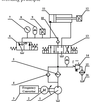
[image:2.516.70.221.404.576.2]1. Fixed displacement pump, 2. Three-phase asynchronous motor, 3. Frequency convertor, 4. Check valve, 5. Filter, 6. Electromagnetic ball valve, 7. Pressure gauge, 8. Accumu-lator, 9. Pressure sensor, 10. Check valve, 11. Cylinder, 12. Force sensor, 13. Solenoid directional valve, 14. Relief valve, 15. Cooler, 16. Oil Tank.
Figure 1. Structure diagram of the prestressed tension hydraulic system.
Figure 1 gives the schematic diagram of the pre-stressed tension hydraulic system. During the tension process, the prestress force is controlled to follow the desired load curve and the sustained load curve. In operation, exerted force of hydraulic (11) is transmit-ted to the controller to generate the control voltage. This voltage is then sent to the frequency convertor (3) to adjust the rotate speed of the motor (2). As the so-lenoid directional valve (13) locates at the left position during the whole operation time, oil outputting from pump (1) could directly enter into the cylinder which in fact is equivalent to the pump-controlled hydraulic system. Exerted force of this system is regulated by the pump outlet’s flowrate which is controlled by the rotate speed of the pump. During the unloading pro-cess, electromagnetic ball valve (6) is opened firstly, and then solenoid directional valve (13) is set to the right position to retract the rod of the cylinder.
2.2 Mathematical model
In the pump-controlled hydraulic part of the pre-stressed tension hydraulic system, elements such as hydraulic pump, frequency convertor have strong nonlinear characters which make the tension system a nonlinear one in essence. For convenience of the con-troller design, this nonlinear system is usually linear-ized to implement its system identification. Getting the structure information of the system such as model order could reduce the identification workload ex-tremely. Hence, according to the real system’s work-ing principle, the mathematical model is induced from both the frequency-motor link and the pump-cylinder link after linearization to determine the structure in-formation.
1) Frequency-motor link
Frequency-motor link demonstrates the relationship between the control voltage and motor’s rotate speed. After linearization, expression of this link could be given as follows:
1
( )
s
2
K u s
f c( )
(1)Where: u sc( )is the control voltage, andKf
repre-sents the V/F coefficient.
2) Pump-asymmetric cylinder link
To simplify the derivation process, following as-sumptions are given: (1) Pressure loss of pipe and its leakage are neglected. (2) Leakage of the pump is laminar flow. (3) Pressure in every chamber of the pump is equivalent and the oil density is constant. (5) The check valve and the electromagnetic directional valve’s dynamic performances are neglected in the whole loading and unloading process.
linkage flow could be calculated as the product of the loading pressure and the pump’s linkage coefficient. Then the pump’s real output could be given as follows
1
p p tp h
q D C p (2)
Where: Dp is the displacement of the pump; 1 is the rotate speed of the motor which equals to the pump one; ph represents the load pressure.
Flowrate entering into the cylinder is the summation of theory flowrate, leakage flowrate and the additional flowrate caused by the oil’s volume change. Here, the theoretical flowrate equals the product of the piston’s sectional area and the stretched speed, while the leak-age flowrate is the product of the load pressure and the cylinder’s leakage coefficient. Then the flow continu-ity equation of the cylinder could be given as follows:
1 4
t h
c tc h
e V p
q C p s A ys
(3)
Where: A1 is the sectional area of the piston; y is the displacement of the cylinder; Ctc is cylinder’s leakage coefficient; Vt is the volume of the cylinder;
e
is the bulk modulus coefficient.
Kinetic equation of the cylinder could be expressed as follows:
2
1 h s
FA p mys BysK y (4) Where: F is the exerted force; m is the total mass of both the piston and the load; B is the equivalent damping of both the cylinder and the load; Ks is the
equivalent elastic coefficient.
From equations (1)-(4), relationship between the control voltage and the exerted force could be given as follows after eliminating the variables of flowrate, pressure and displacement.
2
m B
3 2
1
1 1 1 1 1 1
( 1)
( ) ( )
4 4 4
s s c
K K
t t t s s
e e e
s s
Ku F
V m V B mC V K BC CK
s s A s
A A A A A A
(5)
Where: K2D K Kp f s
According to equation (5), this tension system is a three order one. For the sake of system identification, it’s discretized to equation (6) based on the LP-SVR algorithm.
yx (6)
Where is the coefficient vector,
1, 2, 3, 4, 5, 6
x is the input vector
consisted by the collected control signalu and the exerted force signal y.
y k( 1), y k( 2), y k( 3) (, u k 1) (, u k 2) (, u k 3)
T
x
3 LINEAR PROGRAMMING SUPPORT VECTOR
REGRESSION
After linearized the system model to equation (6), the vector pair (x1,y1) is chosen as the input of the LP-SVR to obtain the coefficient vector .
The model sparsity plays a key role in improving the computational efficiency and alleviating model redundancy. To enhance the sparsity of the model, LP-SVR chooses the l-norm of the coefficient vector
to serve as the regularized matrix to reduce the model complexity and the structure risk.
-insensitive loss function is determined as equa-tion (7):
ˆ , ˆ
1, 2, ,
0 ,
i i i i
y y y y
L i n
otherwise
(7)
Optimization problem of the LP-SVR could be de-scribed as follows:
1 1
ˆ
min ( )
n
i i
i
R C L y y
(8)Where: C makes the tradeoff between the model sparsity and the identification precision.
After introducing the slack variables i ,
1, 2, ,
i n. To strengthen the input data’s flexibil-ity and the LP-SVR’s robustness, optimization prob-lem (8) could be transformed into the following con-strained optimization problem:
1 1
1 1 1 2 1 1
1
1 1 1 2 1 1
1
min
( ( , ) ( , ))
. . ( ( , ) ( , ))
0 1, 2, ,
n n i n
i i n i n n n
i n
n i i n i n n
i
i C
k k y
s t y k k
i n
y y u u
y y u u
(9)
Where: yi1
yi1,yi2,yi3
,
1 1, 2, 3
n yn yn yn
y , ui1
ui1,ui2,ui3
,
1 1, 2, 3
n un un un
u . The elementiof the vector
and their absolute valuesi is decomposed ac-cording to equation (10):
i i i
, i i i
(10)
Where: i, i 0
, i i 0
there are only one pair of i and i to fulfill equation (10). After introducing these two parameters, optimization problem (9) could be re-deduced to equation (11):
1 1
1 1 1 2 1 1
1
1 1 1 2 1 1
1
min ( )
( )( ( , ) ( , ))
. . ( )( ( , ) ( , ))
0 1, 2, ,
n n
i i n
i i
n
i i i n i n n n
i n
i i i n i n n n
i
i
C
k k y
s t k k y
i n
y y u u
y y u u
(11)
Define the vector:
1,1, 1,1,1, ,1, , , ,
T
n n n
C C C
c = (12)
1 1,1, 1,1,1, ,1
(13)
Where:
1, 2, ,
T n
,
1, 2, ,n
.
Then the above optimization problem could be boiled down to the following linear programming problem:
min
. .
, 0, 0 T
s t
K K I
K K I
c
y y
(14)
Where:
1, 2, ,n
T ,
1, 2, ,
T ny y y
y .I
is the nn unit matrix. k1 and k2 are the kernel function, K =k1(yi1,yn1)k2(ui1,un1). Optimiza-tion problem (14) could be finally resolved through Simplex algorithm and Primal-dual Interior Point to get the vectors and . Then elements
i of the LP-SVR’s could be calculated according to equation (10).The exerted force’ estimated expression could fi-nally be given as follows:
1 1 1 2 1 1
ˆn i( ( i , n ) ( i , n ))
i SV
y k k
y y u u (15)Where k1(yi1,yn1) is the autoregression part and 2( i1, n1)
k u u is the moving-average part.
4 IDENTIFICATION OF THE PRESTRESSED
TENSION HYDRAULIC SYSTEM
According to the system identification procedure, a short time step signal with amplitude of 10V and du-ration of 2s which satisfies the persistent excitation condition and, the optimal input signal condition is determined to motivate the prestressed tension hy-draulic system to acquire the I/O data. After filtration and removing mean, the input vector pair( ,x1 y1) of the LP-SVR is constructed as seen in section 3. Aim-ing to improve the identification accuracy and reduc-ing the identification workload, the regularization parameter C and the insensitive function
is opti-mized with values of 0.6472 and 0.0034 according to literature [10]. Kernel functions k1(yi1,yn1) and2( i1, n1)
k u u are chosen to be the linear kernel
func-tion here.
For the convenience of the controller design, the identified regression model shown as equation (15) is converted to the transfer function form as follows:
2
3 2
1.79 95.66 1950
36.65 5645 3 1
( )
53.
s s
s s
G s
s
(16)
Figure 2. Response curve.
Figure 3. Estimation error.
Furthermore, to test the identified model’s general-ization performance, the step signal and the ramp sig-nal is randomly determined to motivate the system where the amplitude of both these two signal is 6V and the ramp signal ’s action time is 6.8s.
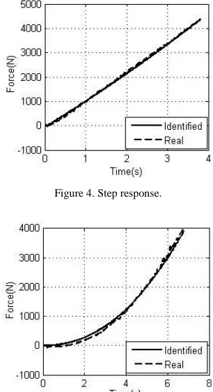
[image:5.516.78.229.120.243.2]Figure 4. Step response.
Figure 5. Ramp response.
Figure 4 shows the output comparison curve of both the identified model and the real system to the step input. As the figure shows, the identified model’s prediction curve could approach the real response curve well which means a good ability to depicts the real system’s step response characteristics.
Figure 5 gives the ramp response curve of both the identified model and the real system. As can be seen, the prediction curve could basically agree with the real response curve although small deviation exists at the start stage and at the end. As models of the elements in the prestressed tension hydraulic system are linear-ized during the identified model structure’s construc-tion process, their high order dynamic characteristics are all neglected which finally result in the mod-el-deviation mentioned above. This modmod-el-deviation could be usually eliminated through designing an ap-propriate controller, especially a robust one.
In conclusion, the identified model gained from the LP-SVR algorithm could represent the characteristics of the real system well, which provides great conven-ience for the controller design.
5 CONCLUSION
Aiming to diminish the great deviation between the prestressed tension hydraulic system and its deduced mathematical model, the linear programming support vector regression method is introduced to conduct the model identification. Results demonstrate that the identified model got from the LP-SVR would well represent the real system which could simplify both the controller design process and its structure.
ACKNOWLEDGEMENT
This paper is sponsored by the Science Foundation for the Scientific Research Institution Technology R&D Program of the Ministry of Science and Technology of China (2012EG124042).
REFERENCES
[1] Jiang Dawei, Fei Shuming, Chen Liyan & Wang Chenglin. 2010. Design of the sleeper tension device.
Journal of Chang chun University of Techonology (Nat-ural Science Edition), 31(3): 305-308.
[2] Haibin Zhang, Yunwen C & Jiang Q I N. 2012. Applica-tion of the new technology of intelligent tension and grouting of pre-stressed concrete. Highways & Trans-portation in Inner Mongolia, 5: 003.
[3] Li W, Liao Q, Luo B & Rao X. 2012. Study and Design of Hydraulic System for Automatic and Intelligent Pre-stressd Tesioning Equipment. Technology of Highway and Transport, 6: 018.
[4] Asgari H, Chen X & Menhaj M B, et al. 2013. Artificial Neural Network–Based System Identification for a Sin-gle-Shaft Gas Turbine. Journal of Engineering for Gas Turbines and Power, 135(9): 092601.
[5] Han X, Xie W F & Fu Z, et al. 2011. Nonlinear systems identification using dynamic multi-time scale neural networks. Neurocomputing, 74(17): 3428-3439. [6] El-Sebakhy EA. 2009. Forecasting PVT properties of
crude oil systems based on support vector machines modeling scheme. Journal of Petroleum Science and Engineering, 64(1-4): 25-34.
[7] Omitaomu OA, Jeong MK, Badiru AB, & Hines JW. 2006. On-line prediction of motor shaft misalignment using fast fourier transform generated spectra data and support vector regression. Journal of Manufacturing Science and Engineering, 128(4): 1019.
[8] Lu Z, Sun J, & Butts K. 2014. Multiscale asymmetric orthogonal wavelet kernel for linear programming sup-port vector learning and nonlinear dynamic systems identification. Cybernetics, IEEE Transactions on, 44(5): 712-724.
[9] Smola A, Scholkopf B, & Ratsch G. 1999. Linear pro-grams for automatic accuracy control in regression. [10] Cherkassky V, & Ma Y. 2004. Practical selection of
[image:5.516.77.228.257.408.2]