"7J//7
~
Issued to: --FC>~..of4:-.
..
-+; _'
~/;Ll~.(-.<·/::. • .JO:~·:::(,,;:--_ _ _ _ _ _ _/1
Branch Office :---,ts-<'t'--'7""---.~~ ... , l . . -Department: _ _ _ _ _ _ _ _ _ _ _ _ _ _ _ _ _
If this manual is misplaced, it should be returned to the above address,
frl
CjD)ol.\I.7
~d.E)~
Customer Engineering Instruction-Reference
This manual, Form Number 231-0002-2, is a major reVISIOn of the preceding Form 231-0002-1. Many minor changes and addi-tions have been made. Major revisions include new punch feed, transport, and brush timing procedures, the addition of solar cell CB instructions and adjustments, and a more complete coverage of belt replacement and retiming procedures.
This manual, Form 231-0002-2 makes obsolete Forms 231-0002-0 and 231-0002-1.
Address comments regarding this publication to:
IBM, Product Publications Department, Rochester, Minnesota
Contents
INTRODUCTION . . . 1-1 FUNCTIONAL PRINCIPLES. . . 1-1
OPERATING LIGHTS AND CONTROLS 1-2
FUNCTIONAL SWITCHES . . 1-3
SPECIFICATIONS .. 1-3
READ FEED. . . 2-1
DRIVE MECHANISM. 2-1
Speed. . . 2-1
READ CLUTCH. . . . 2-1
Principles of Operation. 2-1
Clutch Adjustments. . . . 2-2 Clutch Timing. . . 2-4 Clutch Pulley Assembly Removal 2-4 Clutch Pulley Assembly Installation. 2-4 Clutch Drive Removal. . . 2-4 Clutch Drive Installation. 2-4 FILE FEED. . . 2-5 Principles of Operation. . 2-5 Clutch Adjustments. . . 2-6 Clutch Removal. . . 2-6 Service Checks . . . 2-7 Joggler Adjustments. . . . 2-7
HOPPER AND PICKER KNIVES 2-7
Principles of Operation. . 2-7
Adjustments 2-8
CARD GUIDES. . . 2-9
Adjustments .. CARD LEVERS . . .
Adjustments . BRUSH ASSEMBLY
Adjustments . Timing . . . TRANSPORT AND STACKERS
SELECTION MECHANISM . . . . Principles of Operation .. Chute Blade and Selector Magnet
Adjustment . . . . . . . TRANSPORT ROLL ADJUSTMENTS JAM BAR ADJUSTMENTS .. . STACKERS . . . .
Principles of Operation. . . . stacker Joggler Adjustments Stacker Adjustments . PUNCH FEED . . . .
DRIVE MECHANISM . . . . PUNCH FEED CLUTCH . . . . Principles of Operation .. Clutch Adjustments. . .. . Clutch Timing. . . . . . . Clutch Ratchet Removal. GENEVA . . . . Principles of Operation. Adjustments . . . . Timing . . . ' . . . . . HOPPER AND PICKER KNIVES Principles of Operation .. Adjustments . . . . CARD GUIDES . . . .
Adjustments . . . . FEED ROLLS AND ALIGNER STATIONS.
Principles of Operation. . . . . . '.' Timing Check of Punch Transport. Adjustments of Punch Transport. .
Side Aligner Removal . . . . Forward Aligner Removal . . . .. First Stepped Feed Roll Removal Fourth Upper Feed Roll Removal Fifth Upper Feed Roll Removal. . Second Stepped Feed Roll Removal . . . . ROLL OPENING DEVICE . . . . Principles of Operation. . . . BRUSH ASSEMBLIES . . . . PUNCH UNIT . . . .
Principles of Operation . . . . Punch Unit Removal . . . . Punch Unit Installation . . . . Cam Follower Bearing Adjustments. Cam Follower Assembly Removal. . Cam Follow Assembly Timing . . .. Interposer Setup Bail Adjustment . . Interposer Setup Bail Removal . . . . Magnet Bar Assembly Adjustment. . . . . Magnet Bar Assembly Removal . Magnet Unit Adjustments .. Magnet Unit Removal . . . . Magnet Unit Installation . . . . Interposer Guide Bar Adjustment Interposer and Interposer Link
Removal . . . . Stripper Assembly Removal. . . . Stripper Assembly Installation . . . . .. . Latch Removal. . . .. . Punch Removal . . . . . . . . Punching Registration. . . . Punch Unit Timing . . . . TIMING DRIVE BELTS . . . .
PUNCH FEED INSTALLATION
PROCEDURES . . . . Main Drive Belt . . . . Drive Motor Belt . . . . CR Idler Belt . . . . Timer Index Belt. . . ..
PCCB Drive Belt . . . . Idler Belt . . . . PACB Drive Belt . . . . Second Stepped Feed Roll Drive Belt .. . PLCB Drive Belt . . . . Punch Unit Drive Belt . . . . First Stepped Feed Roll Drive Belt . . . . READ FEED BELT INSTALLATION.
Clutched Feed Roll Drive Belt . Read Feed Belts . . . . ELECTRONIC COMPONENTS '" . . . .
SOLAR CELL CB . . . . Introduction . . . . Principles of Operation .. Timing Procedure . . . . . Adjustment Procedure. . . Removal and Replacement . PERMISSIVE MAKE RELAYS .. . Principles of Operation .. . Contact Replacement . . . . CIRCUIT BREAKERS . . . .
Open Strap Contacts . . . . .
4-9 4-9 4-9 4-9 4-9 4-10 4-10 4-10 4-10 4-10 4-10 4-12 4-12 4-12 4-12 4-13 4-13 4-14 4-14 4-14 4-14 4-14 4-14 4-15 4-15 4-15 4-15 4-15 4-16 4-16 4-17 5-1 5-1 5-1 5-1 5-1 5-1 5-1 5-1 5-3 5-3 5-3 5-3 5-3 5-4 5-4 5-4 6-1 6-1 6-1 6-1 6-2 6-3 6-3 6-3 6-3 6-4 6-4 6-5
SERVICE AIDS . . . " 7-1
CUSTOMER ENGINEERING SERVICE
PANEL . . . . SPECIAL FEATURES . . . . 51-80 COLUMN DEVICE. . . . . . . Mechanical Adjustments . . . . PUNCH FEED READ . . . . Principle of Operation . . . . Card Guide Adjustments . . . . EARLY CARD READ . . . . SERVICE HINTS . . . . INSTALLATION PROCEDURE . . . . READ FEED . . . . Reader Stop Lights. . . . Reader Check Lights . . . . Validity Lights . . . . Picker Knife Timing Check . . . . . . . Brush Timing . . . . Circuit Breaker Timings . . . . PUNCH FEED . . . .
Punch stop Lights. . . . Punch Check Lights . . . . Punch Check Brushes Out of Time .. Punching Registration .. .
Dropping Punches . . . . Multiple Punches . . . . Damaged Cards or Jams .
7-1 8-1 8-1 8-1 8-1 8-1 8-3 8-3 9-1 9-1 9-1 9-1 9-1 9-1 9-1 9-1 9-1 9-1 9-1 9-2 9-2 9-2 9-2 9-2 9-2 PREVENTIVE MAINTENANCE . . . . . . . 10-1
APPROACH TO PREVENTIVE
MAINTENANCE . . . 10-1 PREVENTIVE MAINTENANCE
PROCEDURE . . . 10:"1 1402 CIRCUITS . . . .
POWER SUPPLY AND INTERLOCK
CIRCUITS . . . . Power On Sequence . . . . Power Off Sequence . . . . . . . READ FEED CIRCUITS . . . 11-1
Load Key Operation . . . 11-1 start Key Operation . . . 11-2 Card Reading (RLCB Machines) . . . 11-2 Reader Non-Process Run-Out . . . 11-2 Stop Key Operation . . . 11-2 Card Jam Circuits . . . 11-2 Clutch Check Circuit . . . 11-3 PUNCH FEED CIRCUITS . . . 11-3 Punch Motor Start and Run . . . 11-3 Punch Feed Cycles . . . ; 11-3 Punch Feed Read . . . 11-3 Card Punching . . . 11-3 Punch Check Brushes . . . 11-3 Punch Non-Process Run-Out . . . 11-4 Stop Key Operation. . . .. 11-4 Card Jam Circuits . . . 11-4 Clutch Check Circuit. . . . . . . 11-4 Stacker Select Circuits. . . . . . . 11-4 1402 MODEL 2 ., . . . 12-1 DESCRIPTION . . . 12-1 VARIATIONS BETWEEN THE MODEL 1
INTRODUCTION
The IBM 1402 Card Read-Punch provides the 1401 data processing system with a punch card input and
output. The read feed is a 20 cycle-point feed
equipped with a file feed which has a capacity of 3600 cards. The read feed can process cards at a speed of 800 cards per minute. The punch feed is a 16 cycle-point feed which can punch cards at 250 cards per minute. Five radial stackers are used to accom-plish stacking of the cards from both feeds. The read feed and the punch feed are located at opposite ends of the machine so that cards are fed from the read feed and the punch feed into a transport assembly above the stackers. The card transport system is driven by timing belts wherever possible to reduce machine noise and maintenance. Power supplies for other machines of the system are located in the 1402.
FUNCTIONAL PRINCIPLES
The 1402 Card Read-Punchcanreadcardsata maxi-mum speed of 800 cards per minute. Actual card speed is governed by the program routing. The read feed is equipped with a 3600 card capacity file feed. The cards are fed through the read feed. 9 edge first. face down. The card path is illustrated in the feed schematic diagram (Figure 1-1). As the card passes the read check brushes. 80 columns of the card are read to condition the hole count check planes
in the 1401. It is then moved past the read brushes
where again 80 columns of the card are read and entered into the read area of core storage. At the same time the check planes are conditioned so that a hole count check may be completed. Next. it is transported past the stacker selection station and is directed to the appropriate stacker under control of programming. Three stackers are available to
re-ceive cards from the read feed. The NR (normal
read) stacker is used unless the cards are program-directed to stacker 1 or stacker 2 (8/2).
The 1402 Card Read-Punch will punch cards and check card punching at a maximum speed of 250 cards
per minute. Cards are placed in the 1200 card
ca-pacity hopper. 12 edge first. face down. Card feeding is illustrated in the feed schematic diagram (Figure
1-1). As the card passes the Punch Feed Read
(optional feature). 80 columns of the card are read
into the read areas of core storage of the 1401 if
PFR is called for. Before the card is punched. it is aligned at the aligner station both vertically and
horizontally to insure correct punching registration.
Punching is done by a high-speed punch unit. As the card passes the punch station. circuits are set up in the 1401 which allows the card to be punched with information contained in the punch area of core storage. At the same time the check plane cores are conditioned so that a hole count check may be per-formed. After the card is punched. it is read at the 80 column punch-check brushes to condition the check plane cores so that a hole count check may be
com-pleted. It is then moved past the stacker selection
station and is directed to the appropriate stacker under program control. Three stackers are available to receive cards from the punch feed. The NP (Normal Punch) stacker is used unless the cards are program-directed to stacker 4 or stacker 8 (8/2). The 8/2 stacker cannot be used for collating between the punch and read feeds.
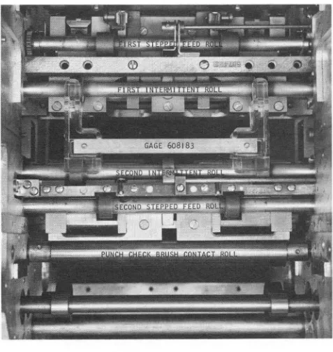
The card transport assembly located between the punch feed and the read feed has a set of six feed rolls along with two select magnets and chute blades for the read feed as well as two select magnets and chute blades for the punchfeed. A jam bar is located in the transport assembly to provide an indication of a jam and stops the machine when a card jam occurs (Figure 1-2).
All stackers are the non-stop unloading radial type stackers with a capacity of 1000 cards each. Cards can be removed from the stackers without
PUNCH FEED TRANSPORT READ m='D
FI RST STEPPED
FEED ROLLS
PUNCH FEED READ STATtON
Figure 1-1. 1402 Feed Schematic
NP
STACKERS
NR READ STATION
NOTE
JAM STOP SWITCH
Figure 1-2. Transport Mechanism
stopping the machine. Two stackers are assigned exclusively to the punch feed. The center (8/2) stacker can be used by either unit, but it must be assigned by the program to one or the other, in any one run (Figure 1-3).
Both feeds are equipped with jam and misfeed detention devices.
OPERA TING LIGHTS AND CONTROLS (Figure 1-4)
Read Switch: Controls the read section of the machine. When this switch is off, the read feed is inoperative.
Figure 1-3. Radial Stacker
1-2
STACKER SELECT MAGNETS
rpUNCH
Punch Switch: Controls the punch section of the machine. When this switch is off, the punch feed is inoperative by program control. Cards can be run into the punch feed with the punch switch off by use of the non-process runout punch switch.
Start Switch: Causes the read feed motor to start when the read switch is on. Punch motor will start
if punch switch is on.
Stop Switch: Used to stop the system. If a pro-gram instruction is in process, it is completed before the stop occurs.
Non- Process Runout- Read Switch: Used to run cards out of the read feed. The last two cards run out will not be processed. The read hopper must be empty to make this switch effective.
Non- Process Runout- Punch Switch: Used to run cards out of the punch feed. The last two cards will not be punched. When the punch switch is on, the hopper must be empty to make this switch effective. Load Switch: Used to start loading instruction cards. PreSSing the load key causes the read feed to operate until a card has passed the read brushes. After the card is read at the read brushes, the pro-gram can start and execute the instruction that is punched in the card. Continued operation is under control of programming. When the punch switch is on, pressing the load key causes the punch drive motor to run.
Check Reset Switch: Must be pressed to reset an error indication before the start key can become operative. This switch is operative only when the feed, in error, is empty of all cards.
Power Light: When power is supplied to the read-punch unit, this light is on.
g
=
PUNCHSTOP CHIPS
STACKER
Figure 1-4. Operating Controls
CHECK RESET
Punch stop Light: A feed failure or a card jam in the punch feed causes the machine to stop and the Punch Stop light to come on.
Validity Light: This light comes on if an invalid character is detected during read operation.
Reader Check Light: This light comes on under control of the data processing system when anerror is detected during card reading.
Punch Check Light: This light comes on under control of the data processing system when an error is detected during the punching of a card.
Stacker Light: If any of the five stackers become full, the stacker light goes on and the machine stops. The light may come on shortly before the machine stops.
Transport Light: This light is turned on by the jam contact. It indicates that a card has jammed in the transport feed roll area.
FUNCTIONAL SWITCHES
Cover Interlocks: When a cover is opened, the respective interlock switch will open the circuit to the punch and reader, motor and run circuits.
Punch Magazine Interlock: When the magazine locking lever is opened, this switch opens the circuit to the punch motor and motor start relays.
Die Lift Interlock: This switch provides the same function as the magazine interlock when the lowering frame is lowered.
Crank Interlock: This is a manually operated switch which must be turned off to insert the hand crank. It provides the same function as the magazine
POWER REAOER CHECK TRANSPORT
BB
interlock while using the hand crank.
g
~
Die Interlock: This switch provides the same function as the magazine interlock when the die is removed or improperly located.
Stacker Switch: This switch operates when any of the 5 stackers are filled. When transferred, it opens the circuit to the punch and reader, start and run circuits. It also closes the circuit to the stacker indicating light when transferred.
Jam Bar Switch: When a jam occurs, this switch provides the same function as the stacker switch except that it completes a circuit to the transport light when transferred.
Joggle Switch: This switch is operated when the hinged front joggler assembly is opened. Itopens the circuit to the reader motor control relay.
Chips 1 and 2 Switches: These switches operate when the chip box is full or removed from the ma-chine. Operation of either switch will open the punch motor and run circuits as well as light up the "chips" indicating lamp.
SPECIFICA TIONS
Dimensions: 57 1/2" wide 29 3/4" deep
45 1/4" high (plus read file feed 14 5/8") Weight:
1300 lbs BTU Rating:
READ FEED
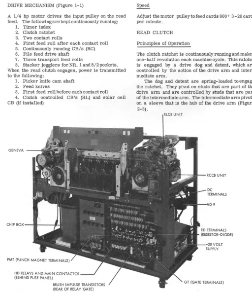
DRIVE MECHANISM (Figure 1-1)
A 1/4 hp motor drives the input pulley on the read feed. The following are kept continuously running:
1. Timer index 2. Clutch ratchet 3. Two contact rolls
4. First feed roll after each contact roll 5. Continuously running CB/s (RC) 6. File feed drive shaft
7. Three transport feed rolls
8. Stacker jogglers for NR, 1 and 8/2 pockets. When the read clutch engages, power is transmitted to the following:
1. Picker knife cam shaft 2. Feed knives
3. First feed roll before each contact roll
4. Clutch controlled CB's (RL) and solar cell CB (if installed)
GENEVA - - - f i
CHIP B O X - - t l I - - -...
PMT (PUNCH MAGNET TERMINALS)
HD RELAYS AND MAIN CONTACTOR _ _ J
(BEHI ND FUSE PANEL)
BRUSH IMPULSE TRANSISTORS (REAR OF RELAY GATE)
Figure 2-1. 1402 Front View
Adjust the motor pulley to feed cards 800+ 3 - 20 cards per minute.
READ CLUTCH
Principles of Operation
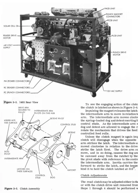
The clutch ratchet is continuously running and makes one-half revolution each machine cycle. This ratchet is engaged by a drive dog and detent, which are controlled by the action of the drive arm and inter-mediate arm.
The dog and detent are spring-loaded to engage the ratchet. They pivot on studs that are part of the drive arm and are controlled by studs that are part of the intermediate arm. The intermediate arm pivots on a sleeve that is the hub of the drive arm (Figure
2-3).
RLCB UNIT
[image:10.616.57.570.111.705.2]SOLAR CELL CB ... I---~.I~
READER DRIVE
~I-I!!~~~l~
MOTOR-60 VOLT SUPPLY
PC (PUNCH CONNECTORS)
Figure 2-2. 1402 Rear View
DRIVE ARM SECURED TO
PULLEY I NTERMEDIA TE ARM PIVOTS ON THIS HUB
I NTERMEDIA TE ARM
DOG
Figure 2-3. Clutch Assembly
2-2
PUNCH DRIVE MOTOR
To see the engaging action of the clutch, assume the clutch is latched as shown in Figure 2-4.
Impulsing the magnet releases the latch and allows the intermediate arm to move in relation to the drive arm. The intermediate arm moves clockwise due to the spring-loaded dog and detent exerting force on the control studs. As the intermediate arm moves, the dog and detent are allowed to engage the ratchet and rotate the mechanism that drives the feed knives and controlled feed rolls.
Unless the clutch magnet is again impulsed, the clutch will disengage when the opposite end of the arm strikes the latch. The intermediate arm, having moved clockwise in relation to the drive arm, will strike the latch first. The drive arm continues to move, and in so doing, causes the dog and detent to be cammed away from the ratchet by the motion of the pivot studs with reference to the control studs on the intermediate arm. Inertia carries the drive arm forward to strike the latch, and the keeper falls be-hind it to hold the clutch latched at 3150.
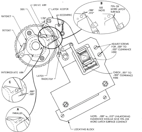
Clutch Adjustments
[image:11.622.33.507.70.732.2] [image:11.622.39.475.84.417.2]DRIVE ARM
KEEPER
RATCHET
Figure 2-4. Magnet Assembly Adjustments
clutch assembly is installed or when complete adjust-ment is to be made of the center plate assembly and clutch magnet assembly. When this is to be made, the
read clutch locating plate gage (PiN 610147) must be
used.
NOTE: Use of this tool will insure a parallel condi-tion between drive arm latch surface and the latch at latch-up time (Figure 2-4A).
Proceed to step 5 for the armature, latch, -and magnet adjustments.
The following. sequence is used to adjust the clutch: 1. Remove clutch pulley as described in Clutch Pulley Assembly Removal Procedure.
2. Remove latch keeper and latch from center plate assembly.
3. Position locating gage on center plate assem-bly studs and clutch pulley assemassem-bly shaft (Figure
B
SEE NOTE
ADJUST SCREWS FOR.020" TO • 022" CLEARANCE HERE
-_-l.--
CHECK. 001" TO .003" CLEARANCE HERENOTE: .008" to .012" UNLATCHING
CLEARANCE SHOULD GIVE 75% (OR MORE) LATCH SURFACE CONTACT
LOCATING BLOCK
2-5). Position and secure locating block withcenter plate assembly as far left as possible. Remove gage. 4. Reinstall latch keeper, spring, and latch. Follow Clutch Pulley Assembly Procedure for re-assembly of clutch pulley re-assembly.
5. Adjust armature pivot bracket to maintain .002" to .005" clearance between armature and core (Figure 2-4).
6. There should be .020" to .022" clearance be-tween armature and yoke with latch against backstop
(Figure 2-4).
7. Manually attract the armature and position the latch assembly plate for a .008" to .012" unlatching clearance between the latch and the clutch drive assembly. Tighten center plate assembly mounting
screws. At this time, there should be at least 75% of
[image:12.615.68.549.51.496.2]HORIZONTAL
Figure 2-5. Latch Assembly Plate Alignment
latched condition (Figure 2-4B).
NOTE: Be sure to keep plate against locating block. 8. Loosen locating block mounting screws and position locating block as far right (ear of locating block against the plate) as possible. Lock mounting screws.
9. Adjust eccentric keeper stop stud to obtain . 000" to .. 020" between clutch drive arm and latch ~er (Figure 2-4C) at latch time.
10. Check for .002" clearance between the step on the ratchet and detent (backlash) with clutch engaged.
If there is more than .002" clearl;l,nce replace with a
. longer detent. "
N9TE: Seven new detents' (PIN 609737 through 609743 are available. These detents are e~ched 1 through 7. Detent#l is .002" longer than·the original 'alld #2 is .002" longer than #1. etc.
Clutch Timin~
Thi/:l adjustment insures that the read feed dynamic timer is in time with the clutch at engaging time.
1. Block the clutch armature attracted.
2. Crapk machine and listen or feel for latch keeper to fall behind &-ive arm. This should happen
at 3150 ± 10. .
. 0 0
3. If the index is not at 315 ± 1 when the latch keeper falls behind the drive arm,loosen the clamped
. 0
hub on the index drive shaft and.,turn the index to 315 . 4. Tighten the clamped hub.
5. If the timer index is moved, the brush timing and CB timing will have to be checked.
Clutch Pulley Assembly Removal (Figure 2-6)
The clutch pulley includes the dogs wd arms that operate them. Remove the pulley as follows:
1. If the same clutch assembly is to be used, spot mark the clutch pulley and 'the picker knife cam shaft pulley to the belt. (This is
to
retain RLCB's, Solar CB, and picker knife timing.)2-4
2. Remove file feed drive belt. 3. Loosen idler for clutch pulley belt.
4. Remove grease fitting on ends of clutch shaft. 5. Loosen retaining clamp and remove clamp and file feed drive pulley together.
6. Remove clutch pulley drive belt.
7. Remove clutch pulley assembly. It may be necessary to loosen V-belt input pulley and move it towards the end of its shaft.
Clutch Pulley Assembly Installation
When a new clutch pulley assembly is installed, the entire procedure listed under Clutch Adjustment should be performed after the following steps have been completed:
1. Be certain that two thrust bearings (washers) are on shaft against clutch ratchet.
2. Install clutch pulley, operating the arms so that the detent and dogfitintohighdwellof ratchet.
3. Place two thrust bearings against clutch pulley.
4. Install clutch retaining clamp (and file feed pulley), allowing no end play of pulley.
5. Install clutch pulley belt with spot marks lined up and adjust idler.
6. Install grease fitting and file feed drive belt. 7. Reposition V-belt input pulley, if moved . 8. Check picker knife timing. RLCB's timing. and solar CB timing.
Clutch Drive Removal (Figure 2-6)
1. Scribe lines along one end and side of unit to maintain'front io.,l!ear,and side to side location.
2. Remove dynamic timer index as follows: a. Remove screw from hand crank. b. Remove two screws from index base. c. Loosen clamped hub on index shaft. d. Unplug index cable.
3. RemoVe four drive belts. a. Contact roll drive (front). b. File feed drive (rear). c. Motor drive (rear).
d. Clutched feed roll drive. Loosen belt
take-up pulley bracket (idler)~:, ; . " ... , .... , ~ . 4. Remove clutch magti.etIeads at terminal block. 5. Remove four hex-head clutch drive assembly mounting screws.
6. Remove assembly through rear.
Clutch Drive Installation
1. Set drive assembly in position from rear. 2. Install four drive assembly mounting screws; do not tighten.
3. Position clutch drive assembly -on scribed lines. Tighten mounting screws.
4. Install dynamic timer index (leave clamped hub
loose). 0 0 . '
REVERSE LOCK
CLUTCH PULLEY ASSEMBL·Y
'----DRiVE PULLEY
Figure 2-6. Clutch Drive Assembly
machine until detent keeper falls behind drive arm.
Tighten clamping hub.
6. Install clutch drive belt and adjust idler pulley.
At this time loosen the picker knife camshaft pulley locking screws.
7. Timing the picker knife camshaft can be accomplished by tripping the read clutch and setting the timer at 2160 for a 2 group brush machine or
o
212 for a 3 group brush machine. Place a card in the hopper up against the first feed rolls. Turn the cam shaft in the normal machine direction until the feed knives touch the card. Tighten the pulley lock screws. This is a starting point for brush timing. Refer to wiring diagram for the final brush timing. Change the picker knife camshaft for the proper brush timing by slipping the drive pulley on the cam shaft.
8. Time RC CB's, using the set screw retained gear on the RC CB shaft.
9. Install the other three belts and unblock the clutch armature.
10. Check the following timings:
o 0
a. Clutch engagement time (315 ± 1 ). b. Brush impulse CB timing.
c. RC CB timing. d. RL CB timing.
TIMER INDEX SHAFT ·
MAGNET ASSEMBLY
FILE FEED
Principle of Operation (Figure 2-7) The file feed consists of two basic units:
1. Upper magazine. 2. Lower magazine.
The upper magazine is the tray which holds up to
3600 cards to be fed into the hopper. This tray is hinged and can be locked at an angle to make the brush area of the machine more accessible.
HELICAL SPRING CLUTCH
Figure 2-7. File Feed
JOGGLER OPERATING
LEVER
When the card level drops below the sensing pads, the additional travel of the joggler forces the joggIer operating lever to follow the low dwell of the front joggler cam. At this time, the tab on the joggler op-erating lever will cause the clutch opop-erating lever to rotate counterclockwise, pivoting the clutch latch out of the step in the clutch sleeve. The helical spring grips the shaft, and the feed rolls are driven. Cards feed until card level in the hopper again reaches the sensing pads and then the clutchlatches.
Cards are automatically front-and-side-joggled in the hopper. Correct operating jogglers produce a deck with almost perfectly straight sides. The front joggler· can be opened for insertion or removal of either cards or card weight.
The card weight is designed to pass through the
lower magazine into the hopper and must be used to
feed the last cards.
The front joggler interlock, mounted under the read hopper, renders the machine inoperative unless the front joggler is closed.
Clutch Adjustments
With the clutch latch against the latch step on the sleeve, loosen the split collar and rotate the collar
2-6
o
/ \
/~
I
'~'
."v.
\
CLUTCH SENSING
LEVER ~
JOGGLER CONTROL LEVER
LOWER MAGAZINE
backwards (opposite normal direction) until stopped by the spring fully uncoiled inside the sleeve. While holding the split collar in this pOSition, rotate the detent gear to 1/16" past detent position. This should result in 1/16" overthrow (Figure 2-8).
Clutch Removal
1. Remove covers and upper and lower
maga-zines.
2. Remove drive unit from machine.
3. Remove. rear pulley and front and rear joggler cams.
NOTE: Mark cams and shaft to maintain relation-ship.
CLUTCH LATCH
CLUTCH 0 ETEN T
4. Remove rear bearing retainer plate.
5. Loosen side joggler cam, clutch hub (with grease fitting), and clutch drive gear on joggler cam shaft. These set screws are seated in undercuts on shaft and must be loosened a full turn. Slide shaft out of rear of unit.
6. Remove clutch assembly through bottom of unit. The clutch can now be dis-assembled and the spring removed.
7. Re-assemble in reverse order. Be careful to have the clutch latch and the detent in their correct positions, and the grease fittings over the slotin the shaft. The clutch drive sleeve and the side joggler cam should hold the clutch together, with the clutch in full mesh. The sleeve and the side joggler cam should hold the clutch together, with the clutch in full mesh. The sleeve and the side joggler cam should not squeeze the clutch so tightly as to cause binding when the clutch is latched. Check all drive unit ad-justments after the unit is replaced in the machines.
Service Checks
1. The front joggler interlocking arm should have approximately 1/16" travel before contact makes.
2. The upper card deck support must be centered between the side frames.
3. The front joggler operating levers must be free of binds between the side plates and the lower magazine.
4. Hopper bed plate springs must be 3/8" ± 1/16" above hopper bed plate.
5. Shims are available to shim the lower maga-zine if the speed nuts interfere with the helical spring clutch.
6. The lower magazine throat should be .020" to .040" above the imaginary plane determined by the tops of the feed rolls (Figure 2- 9) .
Joggler Adjustments
Front Joggler
1. Turn the file feed drive unit until the front joggler cam followers are on the low dwells of the camS. Fill the hopper to just below the sensing pads on the front joggler and close joggler. Set the ad-justing screws on the joggler to just touch the operating arms (Figure 2-10). Undertheseconditions there should be .003" to .010" clearance between the cards and the lower end of the joggling surfaces (the lower end of the joggling surfaces is in line with the top of the card feed knife posts). This clearance is obtained by adjusting the hopper post mounting bar with the set screw (Figure 2-10). The hopper posts will now have to be adjusted (Refer to Hopper Adjust-ments).
2. Turn the file feed drive until the frontjoggler cam followers are on the high dwell of the cams. Fill the hopper with cards to a level even with the top of the sensing pads and close the joggler. Hold the rear
.020 TO .040
Figure 2-9. File Feed Adjustments
cam follower against the cam, and continue to operate the unit. Stop when .005" to .008" clearance appears between the cam follower arm and the adjusting screws. Loosen the clutch operating lever on its pivot shaft and fully seat the clutch latch. With the cam follower against the cam, position the clutch operating lever so that it just touches the turned 'over ear on the cam follower arm (Figure 2-10). Tighten the set screws in the clutch operating lever, securing it to its shaft.
Side Joggler
1. With a two inch column of cards in the hopper, turn the file feed drive until the hopper joggler cam follower is on the high dwell of the cam. Set the adjusting screw for .000" to .005" clearance between the top of the deck and the joggler arm (Figure 2-10A). NOTE: There is no timing relationship between the side and front joggler cams, nor between the cams and the feed knives. The front joggler cams should however, be even with each other.
HOPPER AND PICKER KNIVES
Principles of Operation Figure 2-11.
Figure 2-10. Lower Magazine Throat
I I - - - S I D E JOGGLER
• 000" to • 005" CLEARANCE
2" CARD DECK
Figure 2-10A. Side Joggler Adjustments
2-8
LATCH
CLUTCH OPERATING LEVER
III~I+---ELONGATED HOLE
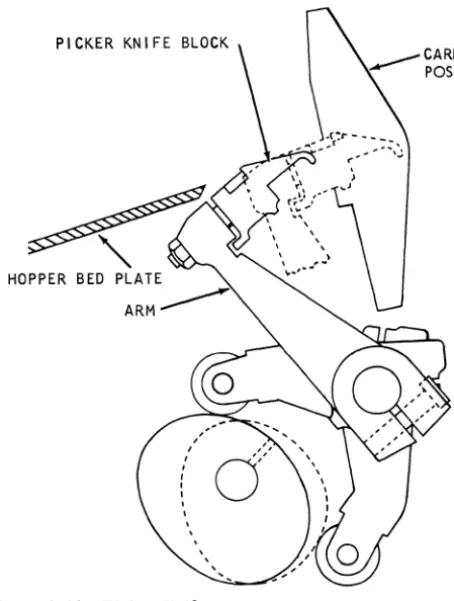
The picker knives travel in an arc and not in a flat plane parallel to the card line. For this reason, to obtain the best possible feeding conditions, the knife blocks must travel evenly through the same arc. The knife blocks are factory adjusted and should never
be changed. ~.
Each picker knife block is fixed on its arm~~ITwo carballoy pieces are inserted in the block surface to resist wear. The inserts are ground to specifications for knife projection and replacement of the picker block is required when the insert becomes worn.
Adjustments
1. Position picker knife cam followers for a maximum of .004" clearance over the entire pe-riphery of the cams, without binding.
PICKER KNIFE BLOCK
[image:18.620.79.306.50.351.2]HOPPER BED
Figure 2-11. Picker Knife
3. With a clearance of .062" ± .005" between the rear hopper side plate and the rear side frame. adjust the front side plate for .016"
to
.021" over the length of the card.NOTE: This adjustment should result in cards centered between the rails in the transport area (5/16" ± 1/32" from the front rail).
4. Adjust the hopper back plate card guide fingers .020"
to
.050" clearanceto
the hopper bed plate fingerS, (Figure 2-12).5.
~osition
the feed knife arms evenly on the shaft so that the feed edge of the picker knife block travels .020" to .030" beyond the trailing edge of a card. when the card is held against the hopper posts. 6. The throat roller must be positioned so that the step indicating the center line of the roller is lined up with the throat knife face.7. The throat opening should be .0095" go and .0105" no-go. Time the picker knife cams to feed a card so that the trailing edge of a card aligns witg
: :
~a:o:; ::s:~o:~
~~~ ~!ra~p;:a=h:!.
NOTE: This is just a referenoe point for making brush timings. When the brushes are on the soribed line (refer to Brush Assembly Adjustment). retime the pioker knife oamshaftto
obtain proper timing.To adjust proceed as follows: ..
a. Loosen clamped hub on pioker knife oarA"
Place a card against the first feed rolls and manually turn the picker camshaft machine di-rection until the feed knives touch the card. Tighten pulley locking screws.
NOTE: Any change in picker knife timing will directly affect RC CB and solar CB (if on machine). Be. sure
to
check brush timings and adjustments .carefully before making these timings.CARD GUIDES
Adjustments
1. Position the first lower card guide for .005" to .015" below the careltline. Position the second lower card guide for .015" tcr .025" below the card line. Adjust by loosenihg the mounting screws in the side frames.
2. Position.the removable upper card guide for .020" to .050" clearance to the first lower card guide assembly.
CARD LEVERS
Adjustments
1. Make sure all card levers are free of binds.
shaft pulley .\';.
• 0
2. Position all card lever contacts to give a mini-mum contact travel of 1/16" when the card lever is being operated by a card.
3. Position card levers and contacts to provide
a minimum of 1/64" rise of the N/O contact strap
off it support.
4. Adjust the contacts for 1/32" minimum air
gap.
5. Time according to timing charts (dynami-cally).
BRUSH ASSEMBLY
Adjustments (Figure 2-13)
1. Insert brush assembly into machine and check for .012" minimum clearance between brush sepa-rator and contact roll with an end to end variation of
.015" maximum. To adjust proceed as follows: a. Loosen four separator holding screws. b. Place brush assembly on flat surface. c. Adjust separator to flat surface. d. Tighten the four screws.
e. Check assembly in machine for correct
clearance.
SPRI NG (2)
BRUSH SEPARATOR MOUNTING
BRUSH TIMING ADJUSTING SCREWS
Figure 2-13. Brush Assembly
2-10
f. If clearance is incorrect, remove assembly
and shift separator in proper direction.
2. Loosen locking screws at either end of brush
assembly and shift block, so that the heels of the brushes are .050" + .030" - .020" off the scribed line on separator toward the stacker (left in read feed) (Figure 2-14).
NOTE: This setting is for the 2 grouped brushes, if the 3 grouped brushes are used, set them on the
scribed line
+
.030" - .020" .3. Adjust the brush assembly for correct lateral tracking of the brushes.
a. Center the brushes in the separatorbyuse
of the two Allen-head set screws in the brush
assembly frames.
NOTE: Do not tighten the set screws to a point where they bind the retractable frames.
b. With the brush holder in place, adjust the screws in the machine side frames for correct brush tracking.
c. Allow .003" clearance to prevent binding,
when removing or replacing the brush assembly.
4. Adjust brush assembly card guide for a mini-mum of .025" clearance to the lower card guide.
Timing
1. Dynamically check brush to be sure that the first and second read stations are a complete machine cycle apart (360°) and within the scribed line settings listed above.
2. Dynamically time the brushes as per wiring diagram by shifting the picker knife timing. Do not accomplish brush timings by shifting brushes off scribed line.
NOTE: The RL CB's and Solar CB (ifused) will have to be retimed after this adjustment.
3 GROUP BRUSH 2 GROUP----/
BRUSH
TRANSPORT AND STACKERS
SELECTION MECHANISM
Principles of Operation
The transport mechanism consists of six continuously running feed rolls that move cards from the feeds to the stacker selected by chute blades. Three of the feed rolls are under control of the read feed. and three are under control of the punch feed. Cards can go into only three of the five stackers from either feed. The stacker into which the card enters is de-termined by the selection mechanism at each end of the transport mechanism (Figure 3-1).
The selection mechanism consists of two chute blades and two control magnets for each of the read
and punch feeds. With the select magnets
de-energized. the cards enter the stacker nearest the feed; stacker NR for the read and stacker NP for the
punch. If the magnet that depresses the lower of the
two chute blades is energized. the cards go into 1 or
4. If the magnet that depresses both chute blades is
energized. the cards from either feed can go into stacker 8/2.
A jam bar is installed over the length of the trans-port mechanism. The bar consists of a spring steel
t:::(
=====~
PUNCH FEED SELECT MAGNETS
COIL
II
COILstrip located just above the normal card line. Any card that is bent enough to flex the metal strip causes a switch to operate. The switch causes the machine to stop and turns on the stop light. A card jam in the feed portion of the machine is detected by other circuits.
Chute Blade and Selector Magnet Adjustment (Figure 3- 2)
1. Lower control key and indicator light panel by loosening four holding screws and pivoting.
2. With pocket selector magnet armatures
at-tracted, adjust each armature for .035" ± .003"
clearance between upper part of stop and armature. 3. Adjust selector magnet assembly (by use of the mounting screws) to position the chute blades
1/32"
+
1/64" - 0 above card line when the magnetsare not energized, and 1/32" + 1/64" - 0 below the
card line when the magnets are energized.
4. Adjust chute blades (use the chute blade mount-ing screw) for 1/32"± 1/64" clearance between end of lower chute blade and lower card guide plate
(Figure 3-3).
5. Chute blade tension should be such that a force
READ FEED SELECT MAGNETS
L -_ _ _ C_O_,L ____
~I I~
__
C_O_,_L ____~
PUNCH FEED CARD
LlNE~
v
POCKET N/P
Figure 3-1. Card Selection Schematic POCKET
4
POCKET 8/2
POCKET I
POCKET N/R
CHECK CHUTE
: l
TENSION WI TH GRAMGAGE AT THI S POINT
ARMATURE STOP
CHUTE BLADE MOUNT! NG SCREW
Figure 3-2. Chute Blade and Select Magnet Adjustments of 280 to 400 grams applied to the 2 or 8 selector magnet armature (at a point just under armature backstop) should hold the armature fully attracted. A force of 110 to 230 grams should be required to hold select magnet 1 or magnet 4 armatures fully attracted.
6. With a chute blade removed and held on a flat surface, the tab containing the chute blade mounting screw hole should project 1/8"± 1/64" above the flat surface.
TRANSPORT ROLL ADJUSTMENTS
1. The lower pressure rolls should be centered directly below the upper rolls. This can be accomp-lished by inserting a .010" feeler gage leaf between the upper and lower rolls and adjusting the lower roll mounting brackets until the feeler gage leaf is parallel to the card line.
'2. Tension on the pressure rolls is adjusted by the lower feed roll shaft mounting screws so that pull of 1.5 1b to 2.5 1b is required to pull a card strip from between the rolls (upper roll not turning). Tension on the front and rear rolls should be within 1/4 1b of each other. The card must be pulled in the same direction as it is fed. After adjusting, be sure locknuts on the mounting screws are tight.
NOTE: Push-pull scale, PiN 9900012, may be used.
_ ...L + 0 IN
32 -1/64 .
I + 0
32 - 1/64 IN.---~I
SHEAR PLATE
CHUTE BLADES
+ 1/64
_ 0 IN.
Figure 3-3. Chute Blade (Top View)
3-2
ADJUSTI NG SCREW
SHEAR PL4TE
Figure 3-4. Jam Bar
JAM BAR ADJUSTMENTS
1. A jam bar must be positioned for .020" to .035" clearance between the formed points and the shear plates over the entire length of the card trans-port and at the junction of the jam bar and jam bar lever (Figure 3-4).
2. The tape must be adjusted so that the switch will be operated with a tape deflectionofl/16".
STACKERS
Principles of Operation (Figure 3-5)
The stackers used on the 1402 are the radial type. The stacker receives the card from the transport mechanism with the card horizontal. The distance from the top of the guide assembly to the lip of the pivot and lever assembly is less than the length of the card. As a result. the front of the card is held by the card restraining lever. and the rear of the card falls, guided by the guide assembly. The radius of the guide assembly is such that as the rear of the card approaches the bottom. the front falls from the card restraining lever that has been supporting it.
The card stops with the back edge on the card alignment lever and the front edge on the card deck support or card previously stacked. Spring tension supports the card alignment lever until 4 to 6 cards accumulate. Their weight overcomes the spring tension supporting the card alignment lever, and lowers the group of cards into the card pusher slide. The pusher slide oscillating front to back works the bottom of the card deck support. This can continue until the card deck support moves out enough to oper-ate the stacker stop microswitch operating arm, which stops the machine. The card jogg1er mech-anism is driven from either or both the punch and read feeds.
The N/R and 1 stacker jogg1ers are operated by the read feed and the N/P and 4 stacker jogg1ers are operated by the punch feed. The 8/2 stacker jogg1er is connected to both the read and punch feeds by means of two helical springs and collars so that it can be operated by either feed.
CARD RESTRAI NI NG
ASSEMBLY GUIDE
ASSEMBLY
CARD DECK SUPPORT
STACKER STOP SWITCH
Figure 3-5. stacker Schematic
Stacker Joggler Adjustments
CARD PUSHER SLIDE
1. The three shaft must be free of binds (align the four bearing bracket assemblies).
2. Maintain 4.000" ± .005" between the bases of the two inside bearing brackets (Figure 3-7).
3. With the center shaft assembly shifted toward
the reader feed and the clutch hubs flush with the spring sleeve. adjust the clutch hub (identified by a red dot) for .003" to .005" clearance while its spring sleeve is flush against the mating hub.
HUB IDENTIFIED WITH RED
HELICAL
MATI NG HUB
CARD ALIGNMENT LEVER 4 - 6 CARDS
ECCENTRIC TO JOGGLE CARD
TO FRONT OF MACHI NE
Stacker Adjustments
1. Make sure all sliding and pivoting parts move freely with no binds.
2. The space between the pocket separators should be 3 5/16" ± 1/64".
3. The pocket separators should be square with transport rails within .015".
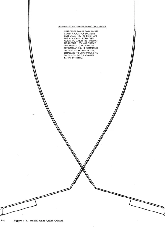
4. Form the radial guide as shown in Figure 3-6.
HELICAL SPRING SLEEVE
READ FEED END
1~.~
___
F_L_U_S_H~
___~
____.O::~::H_~_::_:_5
________.~~1
MOUNTING BRACKETS3...,4,
[image:25.621.39.570.38.770.2]ADJUSTMENT OF STACKER RADIAL CARD GUIDES
Figure 3-6. Radial Card Guide OUtline
PUNCH FEED
DRIVE MECHANISM (Figure 1-1)
A 1/3 hp motor is used to drive the input idler pulley. Through gears and timing belts, the following are kept continuously running:
1. Timer index 2. Clutch ratchet 3. Geneva assembly 4. Intermittent feed rolls 5. Punch unit drive shaft 6. PACB's
7. PCCB's
B. First feed roll after the punch check brushes 9. Three transport feed rolls
10. Stacker jogglers
When the punch clutch engages, power is transmitted to the following:
1. Picker knife cam shaft 2. Feed knives
3. First feed rolls
4. First stepped roll assembly 5. Card aligners
6. Second stepped roll assembly 7. Punch check brush contact roll B. PLCB's
9. Punch feed read brush contact roll (optional feature)
When the punch clutch latches, the intermittent feed rolls are cammed open and though they continue to turn, they cannot feed a card.
PUNCH FEED CLUTCH
Principles of Operation
The punch clutch used on this machine is a 4-tooth o
ratchet~. Theo clutch pawl can engage at 315 ,
45 , 135 , or 225. In order to keep the PCCB's (continuously running) in time with the card and the PLCB's (under control of punch clutch), the PCCB's make and break four times for each machine cycle. Therefore, no matter which tooth the pawl engages in, the PCCB's will give the same timings in relation to the card being fed. The PACB's (high speed con-tinuously running) make and break . :t~: each cycle point. The impulses that are required only need to
be filtered out by PLCB's.
NOTE: The synchronous tooth (3150 ) of the clutch must be used when checking card transport timings USing ga~ nuzs,ber 608~83, otherwise all timings will be 90 , 180 , or 270 offfrom timings specified. All machines after serial number 20600 use one particular tooth as synchronous tooth. This will be the tooth with its driving face opposite the center line of one of the three tapped holes located in the outside collar.
Clutch Adjustments
The clutch assembly is pinned at the factory and should not have to be changed. step 1 would only be performed if a new clutch assembly is installed.
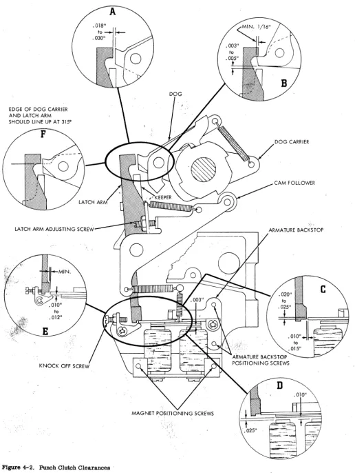
[image:26.627.337.558.416.690.2]1. Set clutch so that latch arm is on the hori-zontal centerline of picker camshaft within .005" (Figure 4-1).
a. At the same time pOSition the unit sideways so that the keeper is flush with the edge of the dog carrier within .010".
b. Form the cam follower arm so that the cam follower is on the middle of the cam surface. 2. Turn machine to low dwell on clutch cam. Trip the clutch and set the adjusting screw for .01B" to
.030" unlatching clearance (Figure 4-2A).
3. Turn the machine to the high dwell on the clutch cam. Check for a minimum ofl/16" overlap of clutch latch arm on the dog and dog carrier (Figure 4-2B). a. Reposition latch arm if necessary (Check item 2).
4. Check for .003" to .005" clearance between dog carrier and keeper. Peen or stone keeper to adjust (Figure 4-2B).
5. With cam follower on high dwell, position . armature backstop plate vertically for .020" to .025" overlap of armature and latch; position horizontally for .010" to .015" relatching clearance (Figure 4-2C).
/
'\
\
o
EDGE OF DOG CARRIER AND LATCH ARM
SHOULD LINE UP AT 3150
F
LATCH ARM ADJUSTING
C"-''''''I_-Figure 4-2. Punch Clutch Clearances'
[image:27.627.34.551.41.728.2]6. Adjust magnet assembly for.OlO" clearance between armature and core nearest pivot and .025" between the armature and core farthest from the pivot when the armature is latched (Figure 4-2D). This adjustment should give .003" to .005" clearance between armature and core nearest the pivot when armature is attracted.
7. The clutch should unlatch with an .008" gage between armature and core farthestfrompivotpoint. It should not unlatch with a .010" gage. Readjust step 5, overlap, if necessary.
8. With the cam follower on high dwell, set the armature knockoff for .010" to .012" clearance be- . tween armature and knockoff (Figure 4-2E).
Clutch Timing
This adjustment insures that the punch feed index is in time with the punchclutchd0!bengagingtjme.
1. Trip clutch between 230 and 300 and turn machine manually until dog engages in clutch ratchet that lines up with set screw in outside collar. . 2. While holding armature in tripped position, continue turning machine until latching surfaces of the clutch latch arm and dog carrier coincide
(Figure 4-2F).
3. At this time the punch feed index should be at 3150 ± 1/20. ;.,:: . ,
• I, 0
a. If punch fe~. index is not at 315 ,loosen clamping hubof index drive pulley and turn index to 3150.
b. Tightet\.clamping hub.
'NOTE: If any change is made in the clutch timing, check the timing of all other punch feed units.
Clutch Ratchet Removal
1. Remove main drive belt.
2.' Remove large input idler pulley.
a. Remove nut in center of idler pulley stud. b. Pull stud and input idler pulley. • 3. Remove screw in end of picker knife cam shaft and pull gear and disc ~embly off shaft.
4. Loosen three se'~9rews and pull ratchet off the assembly. Do not
Jdse
spacerbetW~en the twoinside bearings. ' .
5. Install in reverse order.
6. Re-time clutch, geneva",Jlrid PLCB's . .' " -' .,~,. ,
GEN:£VA , _~~.: '- :- I-',:,-)::
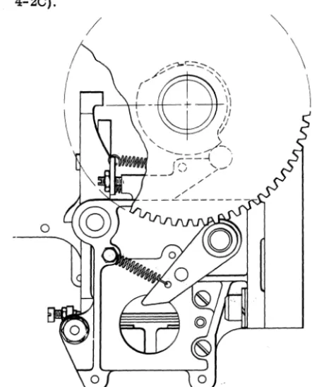
Principies of Operation )Figure 4-3)
.;'"
The geneva. operates on the same' principle
'~4:;ihe
genevas in other high speed punches. Thisgeneva, however, is comparatively simple. It consists of a driVe disc with two pins to drive two geneva discs. There is one set of feed rolls geared to each geneva disc. These are the only feed rolls that have inter-mittent action. A feed roll opening device cams thesetwo sets of feed rolls open at clutch latching time so that they will not feed the card when the clutch latches even though they are continuously running.
When the geneva pins ride into the deep cuts in the geneva discs, the feed rolls are driven by the gears attached to the geneva discs. The cam surface on the geneva drive disc contacts the shallow cuts on the geneva drive discs. When the cam surface is in the shallow cuts of the geneva discs, the intermittent feed rolls are held stationary. The geneva action is repeated every cycle point cl!:using the inters!ttent movement of the card through'the punching station.
Adjustments
NOTE: Do not repair the geneva hOUSing in the field. 1. Locate geneva housing on side frame to pro:, duce .002"
to
.0045" backlash in gears. This setting· is very important. If there is too much backlash, punching registration will be off. If there is no back-lash, the gears will be damaged .. 2 To check for geneva gear backlash: a. Remove puIich unit.
b. Crank machine
to
a point where intermit-tent rolls-are held stationary for punching(a~roximately 40 before line of index).
c. Grip an intermittent roll and turn in both directions, checking for slight wink. Check both sets of rolls at all 12 digit times.
GENEVA DISK
GENEVA PIN
Figure 4-3. Geneva
Timing
Check the clutch timing before proceeding with this adjustment.
o 1. The geneva timing pin should seat at 0 and at alternate cycle points throughout a machine cycle.
2. If gene.va is out of timer: . a. . Turn machine
to
0 on timer index. b. L09sen split hub of geneva inputplilley. c. Crank machine until pin seats and tightens pulley.d. Check timing of punch unit and PACB unit.
/~.
HOPPER AND PICKER KNIVES
Principles of Operation
Refer to hopper and picker knives in Read Feed section.
Adjustments
1. On machines with adjustable left side aligner,
locate left hopper side plate so that there is .057" to .067" clearance to hopper sub .frame.
2. On machines with the stationary left side aligner locate left hopper side plate so that a card will clear left side aligner by .010".
3. The right hopper side plate is adjusted for .008" to .012" clearance over length of the cards. a. Check this clearance by placing approxi-mately a one inch pack of cards in the hopper and insert one or two cards vertically between pack and side plates. One card should be loose; two cards tight.
b. Make sure hopper side plates are at right angles to the first set of feed rolls.
c. On machines with the adjustable left side aligner, check that the card clears the left side aligner by 1/32" to 1/16" with aligners in re-stored position.
4. Position hopper posts for a clearance of .015"
± .002" between hopper posts and a pack of cards
resting against throat knife.
a. Check for a two-card clearance between hopper posts and the pack of cards.
b. Adjust by loosening screws in either end of hopper posts mounting bar and shifting bar the desired amount.
5. Position throat roller assembly laterally so that vertical center line of roller is aligned with edge of throat knife. Determine this by the step in the block that indicates the center line of the roller. " 6. Position cam follower arms for no binding condition over entire periphery of the cams with a maximum clearance of .008" between either cam and follower at any point.
7 . Position feed knive arms evenly on shaft so that the edge of the picker knife block travels .020" to .030" beyond the trailing edge of the card when the card is held against the hopper posts.
.~.;Throat opening should be .0095" go, .0105" ,no-go.
" 9. The picker knife cam is set to deliver a card
. to the first feed rolls at 1850 ± 1/20 . To adjust
pro-. ceed as follows:
a. Loosen cam on shaft.
b.Engage clutch .and turn to 1850 •
c:
Turn cam on shaft until feed knives hold,.:cttrd snug against first feed rolls. d. Tighten cam on shaft.
4-4
CARD GUIDES
There are four card guides that must be kept in proper relationship to the card line. Theyare located as follows:
1. First card guide is located just past the first feed rolls. The first upper card guide is removable and is replaced by a brush assembly if the punch feed read feature is on the machine. The first lower card guide is then altered to accommodate a contact roll. 2. Second card guide is located at the first stepped roll.
3. Third card guide is located at the second stepped roll.
4. Punch stacker transport card guide is located between the punch check brushes and the stackers at the sixth feed roll.
Adjustments
1. Hopper back plate guide should be .008" above
card line.
2. Loosen first lower card guide tie bar holding screws and shift tie bar to obtain .012" to .030" clearance between lower card guide and hopper back plate guide.
3. Trailing edge of first lower card guide should be not more than .005" above or .010" below second lower card guide leading edge.
4. Position first upper card guide for .012" to .030" clearance to lower card guide. Adjust by loosening screws in mounting bar and shifting guide to desired position.
5. Position second upper card guide for .012" to .030" clearance to lower guide.
a. Adjust by loosening tie bar holdingscrews through side frames.
b. Check to make certain the tip of the forward aligner is below the, top surface of lower guide. Adjust by positioning the upper guide because aligners travel in a slot in the upper guide; NOTE: Screws mounting this guide to the bar are 8-36, PIN 607694.
6. Position third upper card guide for .012" to .030" clearance to lower guide. Adjust by loosening mounting bar holding screws and shift guide to desired position.
7. Position punch stacker transport lower card guide for .015" to .025" below. card line level, de-termined by contact roll and sixth feed roll.
FEED ROLLS AND ALIGNER STATIONS
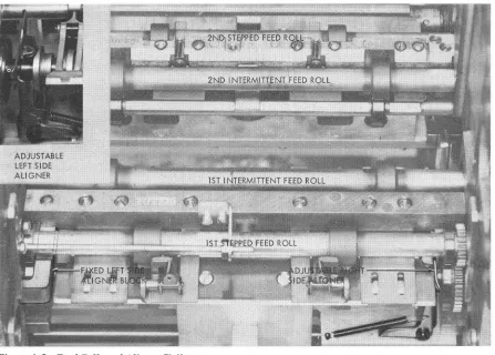
Principles of Operation (Figure4-5)
As the card passes the first upper card guide, it is
Figure 4-5. Feed Rolls and Aligner Stations
because it has a portion of its circumference cut away. When the high dwell of the stepped roll is op-posite the upper roll, the card is fed through the rolls into the first intermittent rolls which are cammed open at this time. When the lowdwell of the stepped roll is opposite the upper roll, collars on the end of the stepped roll assembly shaft prevent the stepped roll from contacting the card.
During the time that tlie card is free from the stepped feed roll and intermittent feed roll, it is aligned-to insure correct punching registration. The forward aligners contact the trailing edge ofthe card and move the card up to the centerline of the punches.
At the same time, the card is aligned toward the column 1 end by the side aligners. Ca~d pressure fingers are used at the aligner station to hold the card so it does not snap or buckle.
After aligning is completed, the first intermittent feed roll closes and the card is fed through the punching station. The second intermittent feed rolls are cammed open as the card is fed into them. They then close, just before the card leaves the first in-termittent feed rolls. After the second inin-termittent feed rolls close, the first intermittent feed rolls are cammed open. Whenthe first intermitted feed rolls open, the feeding of the card through the punch station is under control of the second intermittent feed rolls. The opening and closing of the intermittent feed rolls
prevent buckling or snapping of the card at the punch station.
While punching is being completed, the card is fed into the second stepped roll assembly which does not contact the card at this time. The second stepped roll assembly is 'like the first stepped roll assembly ahead of the aligner station. The second stepped roll contacts the card after the second intermittent feed roll releases the card and feeds it past the punch check brushes into the sixthfeedroll. The sixth feed roll will take over control of card feeding when the second stepped roll comes to the low dwell on its circumference. After card reading the card is under control of the transport and selection mechanism. Refer to Read Feed for the transport and stacker operation.
Timing Check of Punch Transport
o
NOTE: Be sure the synchronous tooth (315 ) is used for these checks. It is the ratchet tooth that is oppo-site one of the tapped holes in the outside collar. These procedures are methods of checking the timing of the first and second stepped feed rolls, first and second intermittent feed rolls, and card aligners. They should NOT be used as final adjustment proce"
dures. Before performing any ofthese steps, be sure
First Stepped Feed Roll and First Intermittent Feed Roll
1. Pivot hopper down.
2. Remove punch feed brushes and PFR brushes or card guide.
3. Trip clutch at 3000 and continue turning
machine until clutch engages (3150 ).
NOTE: The following checks can be made with the
punch unit installed but may be easier with punch unit removed.
4. Continue turning machine to 3330 .
5. Insert a card lengthwise from hopper end so that it is between one roll of the first stepped feed roll. Make sure that the first intermittent feed roll does not interfere with the card.
6. By turning the feed backward. check to
see
thato
the card is free at 331 and is gripped tight by the
first stepped feed roll at 3290 . This indicates first
stepped roll is in time.
7. To check the first intermittent feed roll. turn
machine to 3520 .
8. Insert one card lengthwise between one roll of the first intermittent feed roll. Insert another card
lengthwise between the other roll of the first inter-mittent feed roll.
9. Check to
see
that each card is free at 3530 andis gripped tight at 3570 . This indicates that the first
intermittent feed roll is in time.
Second Intermittent Feed Roll and Second Stepped Feed Roll
1. Trip clutch at 3000 and continue turning
o
machine until clutch engages (315 ).
2. Crank machine to 2900 .
3. Insert card between each of the rolls on the second intermittent feed roll. This card can be in-serted from the punch check brush station.
4. While turnin& feed backward. the car~ should
still be free at 288 and gripped tight at 284 . This indicates that second intermittent roll is in time.
o
5. At 285 a strip of card will pass between the second stepped roll and its uwer pressure rolls. 6. Crank the machine to 293 and the card should
be free. Card should be gripped tightby 2950 . This
assures that the second stepped roll is in time.
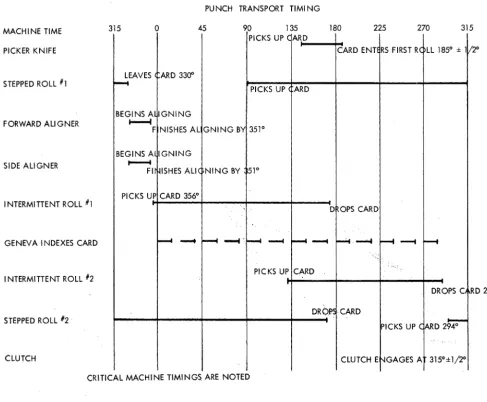
PUNCH TRANSPORT TlMI NG
MACHINE TIME 315 o 45 90 135 180 225 270 315
PICKS UP C ARD
PICKER KNIFE CARD ENTE RS FIRST RC LL 1850 ± 111: 20
LEAVES ARD 3300 STEPPED ROLL #1
r---t
PICKS UP ARD
BEGINS A IGNING FORWARD ALIGNER
...
F NISHES AL GNING BY 3510
BEGINS A IGNING
SIDE ALIGNER ~
FI ISHES ALI ( NING BY 510
I NTERMITTENT ROLL #1
PICKS UP CARD 3560
D OPS CARD
GENEVA INDEXES CARD
--
--
~-
--
...
~~-
r---t
INTERMITTENT ROLL 112 PICKS UP CARD
DROPS C RD 2860
STEPPED ROLL 112·
DROPS CARD
PICKS UP C
ARD2~
CLUTCH CLUTCH E '-IGAGES A 315°±1j2°
[image:31.630.36.523.311.713.2]CRITICAL MACHINE TIMINGS ARE NOTED
Figure 4-4.
Forward and Side Aligners
For checking these timings, the punch unit must be removed. The first stepped feed roll must be in time before checking the aligners.
1. Latch the die into position to serve as a card guide.
NOTE: Die card guide gage 610094 will be furnished with machines containing the redesigned die and stripper 601981 to use in place of die.
[image:32.612.82.321.195.448.2]2. Insert gage 608183 (Figure 4-6).
Figure 4-6. Gage Position in Punch station
3. Pivot the hopper up and place cards in the o
hopper. Trip the clutch at 300 and continue turning the machine until the clutch engages (3150). Feed
cards manually for two card cycles.
4. Continue turning the machine and check to see that a card finishes forward aligning to within .005"
of the "forward aligner timing marks" on the gage at 3510 (Figure 4-7). This determines that the for-ward aligner is timed correctly.
NOTE: The following step is necessary on machines with an adjustable left side aligner.
5. With the machine still at 3510, check to see
that the left side aligner surface is against the card and is 37/64" from the inside of the left side frame. Check to see that the right side aligner is just
o touching the card at 351 .
NOTE: The following step is necessary on machines with a fixed left side aligner block.
6. Check for .010" to .020" gap between card and left side aligner block under the following con-ditions.
a. The card must be fed while being held against the left side plate.
FORWARD ALIGNER TIMING MARKS
Figure 4-7. Gage 608183 Timing Mark
b. The check must be made prior to alignment.
7. When feeding cards held against the right hopper side plate, check the right side aligner surface for .005" minimum clearance to a card when a card is fed into the aligner station but prior to side aligning.
Adjustments of Punch Transport
NOTE: Be sure all power has been removed from the machine.
First Stepped Feed Roll
NOTE: The first stepped feed roll can be timed with the punch unit in the machine, however it is easier with the punch unit removed.
1. Pivot hopper down and remove punch feed brushes and the PFR brushes or the removable card guide.
2. Trip clutch at 3000 and manually turn machine to 3300.
3. Loosen split hub of pulley located onfrontend of first stepped feed roll.
4. While keeping machine at 3300• turn first stepped feed roll by hand and feed a card lengthwise through one roll of the first stepped feed roll. Make sure card is not passing through intermittent rolls.
5. At the point at which the first stepped feed roll stops feeding the card, rotate roll slightly until card experiences light drag.
6. Hold roll at this position and tighten the pulley previously loosened in step 3.
7. Check to see that the card is held tight by the first stepped feed roll at 3290 and is free at 3310.
8. Retime the first intermittent feed roll.
9. Check second stepped feed roll and retime if
necessary.
First Intermittent Feed Roll
The first stepped feed roll must be in proper time before timing·the first intermittent feed roll. For a timing check, refer to Timing Check, First Stepped Feed Roll and First Intermittent Feed Roll. Steps 1 thru 6.
easier with the punch unit removed.
1. Pivot hopper down and remove punch feed brushes and the PFR brushes or removable card guide.
2. Trip clutch at 3000 and turn machine to 3520.
3. Insert one card lengthwise between one roll of the first intermittent feed roll. Insert another card lengthwise between the other roll of the first inter-mittent feed roll.
4. Turn machine to 3560.
5. Adjust eccentrics* at each end of first inter-mittent feed roll shaft so that each card experiences light drag. Keep high side of eccentrics (indicated by the punch marks on the eccentrics) faCing punch marks on intermittent feed roll opening arms (Figure 4-8).
6. Check to see that each card is free at 3530 and is gripped tight at 3570.
Second Intermittent Feed Roll
The second stepped feed roll must be in proper time before timing the second intermittent feed roll. For a timing check, refer to Timing Check, Second Inter-mittent Feed Roll and Second Stepped Feed Roll, steps 1, 5, and 6.
NOTE: The second intermittent feed roll can be timed with the punch unit in the machine, however it is easier with the punch unit removed.
1. Remove punch feed brushes and PFR brushes or removable card guide.
2. Trip clutch at 3000 and turn machine to 2900 3. Insert one card lengthWise between one roll of the second intermittent feed roll. Insert another card lengthwise between the other roll of the second inter-mittent feed roll.
4. Turn machine backward to 2860.
5. Adjust the eccentrics* at each end of the
, second intermittent feed roll shaft so that each card